Page 1270 of 1399

SR16E−03
−
STEERING TILT STEERING COLUMN
SR−19
1996 LAND CRUISER (RM451U)
INSTALLATION
1. INSTALL STEERING COLUMN ASSEMBLY
(a) Torque the 2 column assembly set nuts and 2 set bolts.
Torque:25 N·m (250 kgf·cm, 18 ft·lbf)
(b) Connect the 3 connectors.
2. INSTALL SLIDING YOKE SUB −ASSEMBLY
Temporarily tighten the bolt A.
3. CONNECT SLIDING YOKE SUB−ASSEMBLY
(a) Align the matchmarks on the yoke sub−assembly and
worm gear valve body shaft.
(b) Torque the bolt B. Torque: 34 N·m (350 kgf·cm, 25 ft·lbf)
(c) Torque the bolt A.
Torque: 34 N·m (350 kgf·cm, 25 ft·lbf)
4. INSTALL LINK JOINT PROTECTOR
Torque the 2 bolts. Torque: 12 N·m (120 kgf·cm, 9 ft·lbf)
5. TORQUE 4 COLUMN HOLE COVER SET BOLTS Torque: 13 N·m (130 kgf·cm, 9 ft·lbf)
6. INSTALL COMBINATION SWITCH WITH SPIRAL CABLE
(a) Tighten the 4 screws.
(b) Connect the airbag connector.
(c) Connect the 2 connectors.
7. INSTALL UPPER AND LOWER COLUMN COVERS
Tighten the 5 screws.
8. INSTALL NO.2 HEATER TO REGISTER DUCT
9. INSTALL INSTRUMENT LOWER FINISH PANEL
(a) Tighten the 4 panel set screws.
(b) Connect the hood lock control cable and fuel lid control cable.
10. CENTER SPIRAL CABLE
(a) Check that the front wheels are facing straight ahead.
(b) Turn the cable counterclockwise by hand until it becomes harder to turn the cable.
(c) Then rotate the cable clockwise about 3 turns to align the
red mark.
HINT:
The cable will rotate about 3 turns to either left or right of the
center.
Brought to you by BirfMark
Brought to you by BirfMark
Version 1.11 - 03/16/2010
Page 1271 of 1399

SR−20
−
STEERING TILT STEERING COLUMN
1996 LAND CRUISER (RM451U)
11. INSTALL STEERING WHEEL
(a) Align the matchmarks on the wheel and main shaft as-
sembly.
(b) Torque the wheel set nut. Torque: 34 N·m (350 kgf·cm, 25 ft·lbf)
(c) Connect the connector.
12. INSTALL STEERING WHEEL PAD
NOTICE:
Make sure the wheel pad is installed to the specified
torque. If the wheel pad has been dropped, or there are
cracks, dents or other defects in the case or connector, re-
place the wheel pad with a new one. When installing the
wheel pad, take care that the wirings do not interfere with
other parts and are not pinched between other parts.
(a) Connect the airbag connector.
(b) Install the wheel pad after confirming that the circumfer-
ence groove of the torx screws is caught on the screw
case.
(c) Using a torx socket wrench, torque the 2 screws. Torque: 9.0 N·m (90 kgf·cm, 78 in.·lbf)
(d) Install the steering wheel lower No.2 and No.3 cover.
13. CHECK STEERING WHEEL CENTER POINT
Brought to you by BirfMark
Brought to you by BirfMark
Version 1.11 - 03/16/2010
Page 1275 of 1399

SR16H−01
R08084
R08066
Soft Jaws
R13187
Press
SST
SST
R08067
Screwdriver
SR−24
−
STEERING POWER STEERING VANE PUMP
1996 LAND CRUISER (RM451U)
DISASSEMBLY
NOTICE:
When using a vise, do not overtighten it.
1. MEASURE POWER STEERING VANE PUMP ROTAT-
ING TORQUE
(a) Check that the pump rotates smoothly without abnormal noise.
(b) Using a torque wrench, check the pump rotating torque. Rotation torque:
0.3 N·m (2.8 kgf·cm, 2.4 in.·lbf) or less
2. REMOVE SUCTION PORT UNION
(a) Remove the bolt.
(b) Remove the O−ring from the union.
3. REMOVE VANE PUMP DRIVE GEAR
(a) Using soft jaws on a vise, clamp the gear in the vise.
NOTICE:
Be careful not to damage the gear.
(b) Remove the gear set nut.
(c) Using SST, press out the gear.
SST 09527−10011
NOTICE:
Be careful not to damage the gear. To avoid dropping the
PS pump assembly, support the pump assembly with your
hand.
(d) Remove the woodruff key from the vane pump shaft.
4. REMOVE PRESSURE PORT UNION, FLOW CONTROL
VALVE AND SPRING
Remove the O−ring from the union.
5. REMOVE REAR HOUSING AND WAVE WASHER
(a) Using 2 screwdrivers, remove the snap ring.
NOTICE:
Take care not to damage the housing.
Brought to you by BirfMark
Brought to you by BirfMark
Version 1.11 - 03/16/2010
Page 1281 of 1399

R12473
SR168−01
SR0097
−
STEERING STEERING WHEEL
SR−7
1058
Author�: Date�:
1996 LAND CRUISER (RM451U)
STEERING WHEEL
INSPECTION
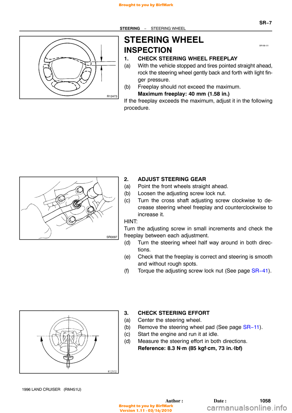
1. CHECK STEERING WHEEL FREEPLAY
(a) With the vehicle stopped and tires pointed straight ahead,
rock the steering wheel gently back and forth with light fin-
ger pressure.
(b) Freeplay should not exceed the maximum. Maximum freeplay: 40 mm (1.58 in.)
If the freeplay exceeds the maximum, adjust it in the following
procedure.
2. ADJUST STEERING GEAR
(a) Point the front wheels straight ahead.
(b) Loosen the adjusting screw lock nut.
(c) Turn the cross shaft adjusting screw clockwise to de- crease steering wheel freeplay and counterclockwise to
increase it.
HINT:
Turn the adjusting screw in small increments and check the
freeplay between each adjustment.
(d) Turn the steering wheel half way around in both direc- tions.
(e) Check that the freeplay is correct and steering is smooth and without rough spots.
(f) Torque the adjusting screw lock nut (See page SR−41).
3. CHECK STEERING EFFORT
(a) Center the steering wheel.
(b) Remove the steering wheel pad (See page SR−11).
(c) Start the engine and run it at idle.
(d) Measure the steering effort in both directions.
Reference: 8.3 N·m (85 kgf·cm, 73 in.·lbf)
Brought to you by BirfMark
Brought to you by BirfMark
Version 1.11 - 03/16/2010
Page 1282 of 1399
SR−8
−
STEERING STEERING WHEEL
1059
Author�: Date�:
1996 LAND CRUISER (RM451U)
HINT:
Be sure to consider the tire type, pressure and contact surface
before making your diagnosis.
(e) Torque the steering wheel set nut.
Torque: 34 N·m (350 kgf·cm, 25 ft·lbf)
(f) Install the steering wheel pad (See page SR−19).
Brought to you by BirfMark
Brought to you by BirfMark
Version 1.11 - 03/16/2010
Page 1284 of 1399

R08069
R08082
R08066
Soft Jaws
−
STEERING POWER STEERING VANE PUMP
SR−31
1996 LAND CRUISER (RM451U)
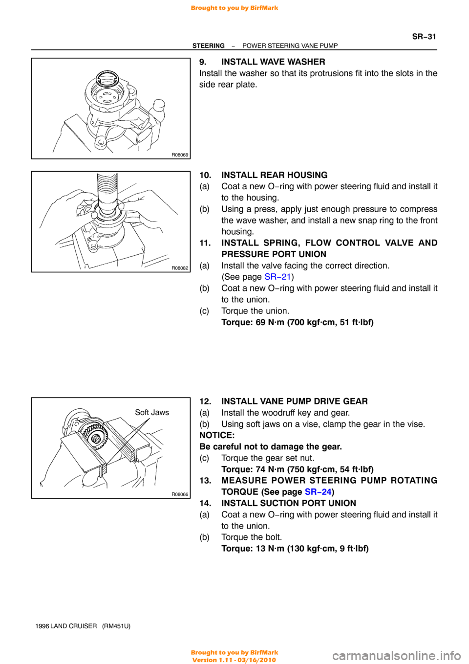
9. INSTALL WAVE WASHER
Install the washer so that its protrusions fit into the slots in the
side rear plate.
10. INSTALL REAR HOUSING
(a) Coat a new O−ring with power steering fluid and install it
to the housing.
(b) Using a press, apply just enough pressure to compress the wave washer, and install a new snap ring to the front
housing.
11. INSTALL SPRING, FLOW CONTROL VALVE AND PRESSURE PORT UNION
(a) Install the valve facing the correct direction. (See page SR−21 )
(b) Coat a new O −ring with power steering fluid and install it
to the union.
(c) Torque the union. Torque: 69 N·m (700 kgf·cm, 51 ft·lbf)
12. INSTALL VANE PUMP DRIVE GEAR
(a) Install the woodruff key and gear.
(b) Using soft jaws on a vise, clamp the gear in the vise.
NOTICE:
Be careful not to damage the gear.
(c) Torque the gear set nut. Torque: 74 N·m (750 kgf·cm, 54 ft·lbf)
13. MEASURE POWER STEERING PUMP ROTATING
TORQUE (See page SR−24 )
14. INSTALL SUCTION PORT UNION
(a) Coat a new O −ring with power steering fluid and install it
to the union.
(b) Torque the bolt.
Torque: 13 N·m (130 kgf·cm, 9 ft·lbf)
Brought to you by BirfMark
Brought to you by BirfMark
Version 1.11 - 03/16/2010
Page 1285 of 1399
SR16K−01
R13336
R13315
Stopper
SR−32
−
STEERING POWER STEERING VANE PUMP
1996 LAND CRUISER (RM451U)
INSTALLATION
1. INSTALL PS VANE PUMP ASSEMBLY
(a) Coat a new O −ring with power steering fluid and install it
to the vane pump assembly.
(b) Torque the 2 nuts. Torque: 36 N·m (370 kgf·cm, 27 ft·lbf)
2. CONNECT PRESSURE FEED TUBE
Torque the union bolt with 2 new gaskets. Torque: 56 N·m (575 kgf·cm, 42 ft·lbf)
HINT:
Make sure the stopper of the tube is touching the PS pump
body, as shown then torque the union bolt.
3. CONNECT RETURN HOSE
4. BLEED POWER STEERING SYSTEM (See page SR−3 )
Brought to you by BirfMark
Brought to you by BirfMark
Version 1.11 - 03/16/2010
Page 1294 of 1399

SR16P−01
−
STEERING POWER STEERING GEAR
SR−41
1996 LAND CRUISER (RM451U)
REASSEMBLY
NOTICE:
When using a vise, do not overtighten it.
1. COAT WITH MOLYBDENUM DISULFIDE LITHIUM
BASE GREASE (See page SR−33 )
2. INSTALL WORM GEAR VALVE BODY ASSEMBLY
(a) Coat 2 new O−rings with power steering fluid and install them to the gear housing.
(b) Secure the gear housing on SST and clamp SST in vise. SST 09630−00014 (09631 −00142)
(c) Install the valve body assembly while supporting the worm gear with your fingers so that it does not rotate.
(d) Torque the 4 bolts. Torque: 61 N·m (620 kgf·cm, 45 ft·lbf)
NOTICE:
Be careful not to damage the teflon ring.
(e) Using SST and a torque wrench, check the valve body as-
sembly rotating torque.
SST 09616−00010
Rotating torque:
0.3 − 0.5 N·m (3 − 5.5 kgf·cm, 2.6 − 4.8 in.·lbf)
HINT:
Hold the worm gear to prevent it from turning.
If rotating torque is not correct, replace the worm gear valve
body assembly.
3. INSTALL POWER PISTON PLUNGER GUIDE, POWER
PISTON PLUNGER, COMPRESSION SPRING AND
POWER PISTON PLUNGER GUIDE NUT
(a) Coat a new O−ring with power steering fluid.
(b) Install the O−ring to the plunger guide nut and install the plunger guide nut with a hexagon wrench (10 mm).
Torque: 20 N·m (205 kgf·cm, 15 ft·lbf)
Brought to you by BirfMark
Brought to you by BirfMark
Version 1.11 - 03/16/2010