Page 1176 of 1399

REMOVAL
1. REMOVE REAR WHEEL
Torque:
Steel wheel: 147 N·m (1,500 kgf·cm, 109 ft·")
SA1VP−01
R08418
−
SUSPENSION AND AXLE COIL SPRING AND REAR SHOCK ABSORBER
SA−11 3
1996 LAND CRUISER (RM451U)
REMOVAL
1. REMOVE REAR WHEEL
Torque:
Steel wheel: 147 N·m (1,500 kgf·cm, 109 ft·lbf)
Aluminum wheel: 103 N·m (1,050 kgf·cm, 76 ft·lbf)
2. REMOVE REAR SHOCK ABSORBER
(a) Remove the lower bolt holding the shock absorber from the rear axle housing.
Torque: 64 N·m (650 kgf·cm, 47 ft·lbf)
(b) Remove the retainer and 2 cushions, disconnect the shock absorber.
(c) Remove the 2 upper bolts and shock absorber. Torque: 50 N·m (510 kgf·cm, 37 ft·lbf)
(d) Remove these parts from the shock absorber:
�Nut
�3 Retainers
�2 Cushions
�Bracket
Torque: 69 N·m (700 kgf·cm, 51 ft·lbf)
3. DISCONNECT STABILIZER BAR BRACKETS FROM
REAR AXLE HOUSING (See page SA−124 )
4. DISCONNECT LATERAL CONTROL ROD FROM REAR AXLE HOUSING (See page SA−11 8 )
5. REMOVE COIL SPRING
(a) Begin to lower the axle housing.
HINT:
Be careful not to snap the brake line and parking brake cable.
(b) With lowering the rear axle housing, remove the coil spring and insulator.
HINT:
Check that the coil spring end is installed correctly.
If the coil spring end is not in the correct position, reinstall the
coil spring.
Brought to you by BirfMark
Brought to you by BirfMark
Version 1.11 - 03/16/2010
Page 1177 of 1399
SA−11 4
−
SUSPENSION AND AXLE COIL SPRING AND REAR SHOCK ABSORBER
1996 LAND CRUISER (RM451U)
(c) Remove the bolt and follow spring from the frame.
Torque: 28 N·m (290 kgf·cm, 21 ft·lbf)
Brought to you by BirfMark
Brought to you by BirfMark
Version 1.11 - 03/16/2010
Page 1181 of 1399
SA1VU−01
SA−11 8
−
SUSPENSION AND AXLE REAR LATERAL CONTROL ROD
975
Author�: Date�:
1996 LAND CRUISER (RM451U)
REAR LATERAL CONTROL ROD
REMOVAL
1. REMOVE REAR WHEEL
Torque:
Steel wheel: 147 N·m (1,500 kgf·cm, 109 ft·lbf)
Aluminum wheel: 103 N·m (1,050 kgf·cm, 76 ft·lbf)
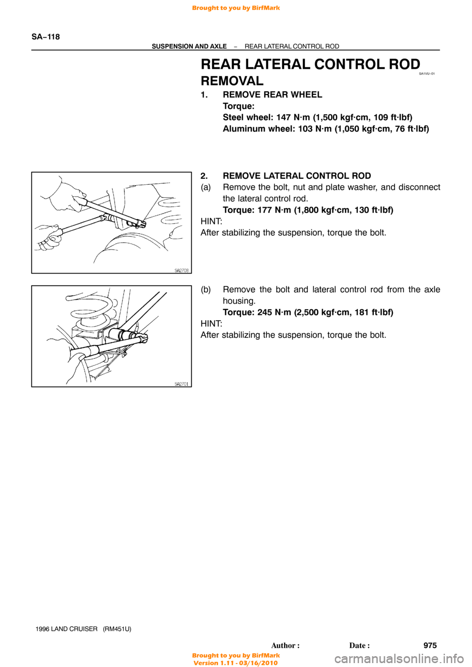
2. REMOVE LATERAL CONTROL ROD
(a) Remove the bolt, nut and plate washer, and disconnect the lateral control rod.
Torque: 177 N·m (1,800 kgf·cm, 130 ft·lbf)
HINT:
After stabilizing the suspension, torque the bolt.
(b) Remove the bolt and lateral control rod from the axle housing.
Torque: 245 N·m (2,500 kgf·cm, 181 ft·lbf)
HINT:
After stabilizing the suspension, torque the bolt.
Brought to you by BirfMark
Brought to you by BirfMark
Version 1.11 - 03/16/2010
Page 1184 of 1399
SA1VX−01
−
SUSPENSION AND AXLE REAR UPPER AND LOWER CONTROL ARM
SA−121
978
Author�: Date�:
1996 LAND CRUISER (RM451U)
REAR UPPER AND LOWER
CONTROL ARM
REMOVAL
1. REMOVE REAR WHEEL
Torque:
Steel wheel: 147 N·m (1,500 kgf·cm, 109 ft·lbf)
Aluminum wheel: 103 N·m (1,050 kgf·cm, 76 ft·lbf)
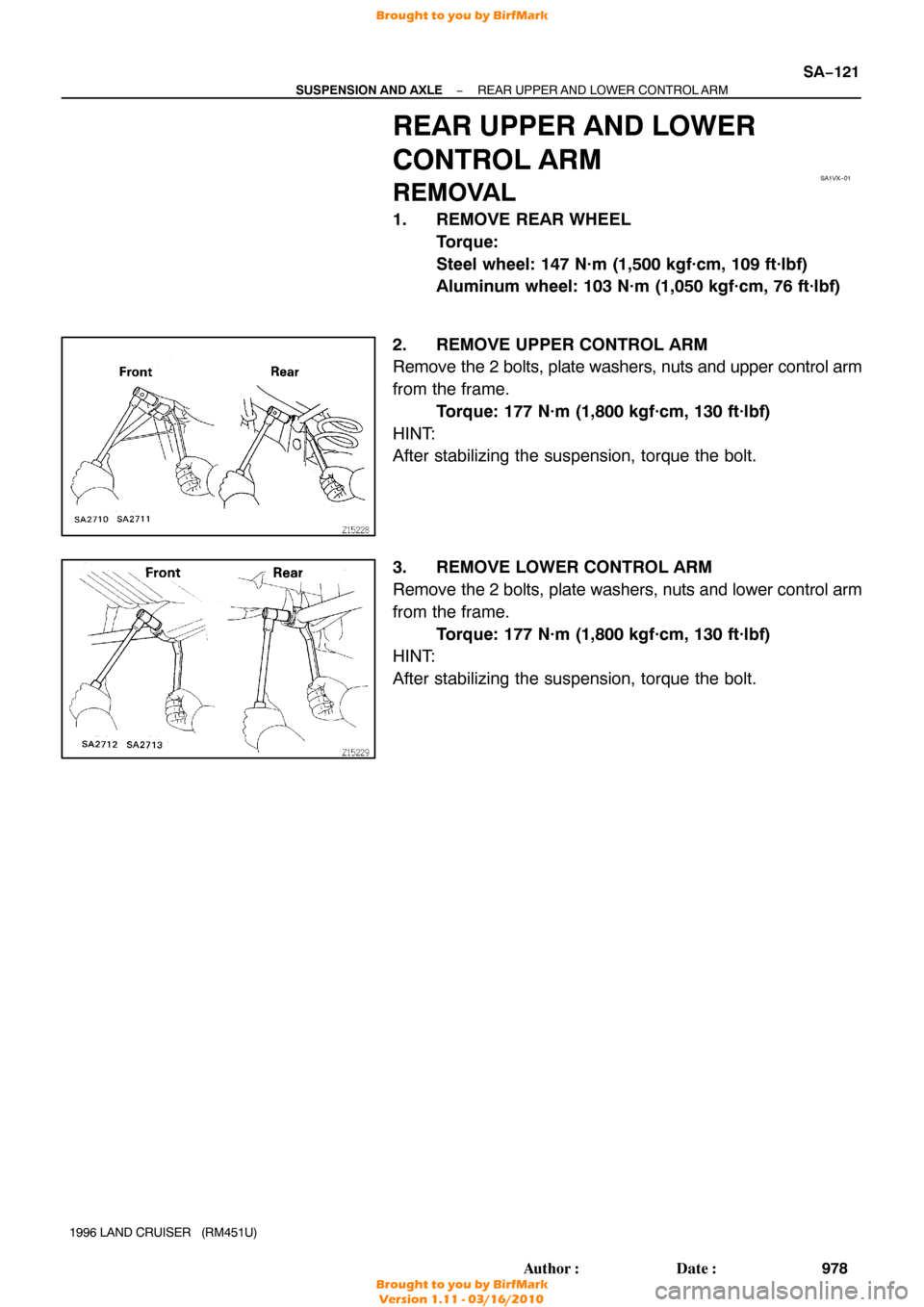
2. REMOVE UPPER CONTROL ARM
Remove the 2 bolts, plate washers, nuts and upper control arm
from the frame. Torque: 177 N·m (1,800 kgf·cm, 130 ft·lbf)
HINT:
After stabilizing the suspension, torque the bolt.
3. REMOVE LOWER CONTROL ARM
Remove the 2 bolts, plate washers, nuts and lower control arm
from the frame. Torque: 177 N·m (1,800 kgf·cm, 130 ft·lbf)
HINT:
After stabilizing the suspension, torque the bolt.
Brought to you by BirfMark
Brought to you by BirfMark
Version 1.11 - 03/16/2010
Page 1187 of 1399
SA1W0−01
SA−124
−
SUSPENSION AND AXLE REAR STABILIZER BAR
981
Author�: Date�:
1996 LAND CRUISER (RM451U)
REMOVAL
REMOVE STABILIZER BAR
(a) Loosen the 2 bolts and nuts.
Torque: 25 N·m (260 kgf·cm, 19 ft·lbf)
HINT:
After stabilizing the suspension, torque the nut.
(b) Remove the nuts and disconnect the stabilizer bar with the links from the bracket.
Torque: 15 N·m (153 kgf·cm, 11 ft·lbf)
HINT:
After stabilizing the suspension, torque the nut.
(c) Remove the 2 bolts, nuts and links from the stabilizer bar.
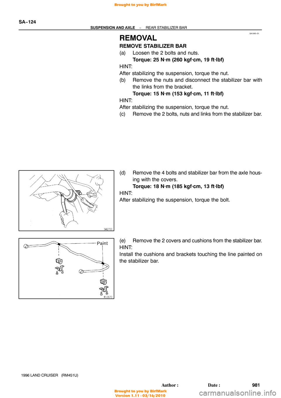
(d) Remove the 4 bolts and stabilizer bar from the axle hous- ing with the covers.
Torque: 18 N·m (185 kgf·cm, 13 ft·lbf)
HINT:
After stabilizing the suspension, torque the bolt.
(e) Remove the 2 covers and cushions from the stabilizer bar.
HINT:
Install the cushions and brackets touching the line painted on
the stabilizer bar.
Brought to you by BirfMark
Brought to you by BirfMark
Version 1.11 - 03/16/2010
Page 1191 of 1399

8. FUEL SYSTEM
(a) When disconnecting the high fuel pressure line, a large
amount of gasoli")
FI1654
Fulcrum Length
30 cm
SST
−
SFI SFI SYSTEM
SF−3
631
Author�: Date�:
1996 LAND CRUISER (RM451U)
8. FUEL SYSTEM
(a) When disconnecting the high fuel pressure line, a large
amount of gasoline will spill out, so observe the following
procedures:
(1) Disconnect the fuel pump connector.
(2) Start the engine. After the engine has stopped onits own, turn off the ignition switch.
(3) Put a container under the connection.
(4) Slowly loosen the connection.
(5) Disconnect the connection.
(6) Plug the connection with 2 rubber plugs.
(7) Reconnect the fuel pump connector.
(b) When connecting the union bolt on the high pressure pipe
union, observe the following procedures:
(1) Always use a new gasket.
(2) Tighten the union bolt by hand.
(3) Tighten the union bolt to the specified torque.
Torque: 29 N·m (300 kgf·cm, 21 ft·lbf)
(c) When connecting the flare nut on the high pressure pipe union, observe the following procedures:
(1) Apply a light coat of engine oil to the flare and tight-
en the flare nut by hand.
(2) Using SST, tighten the flare nut to the specified torque.
SST 09631−22020
NOTICE:
Do not rotate the fuel pipe, when tightening the flare nut.
Torque: 30 N·m (310 kgf·cm, 22 ft·lbf)
HINT:
Use a torque wrench with a fulcrum length of 30 cm (11.81 in.).
Brought to you by BirfMark
Brought to you by BirfMark
Version 1.11 - 03/16/2010
Page 1196 of 1399

REMOVAL
CAUTION:
Do not smoke or work near an open flame when working on
the fuel pump.
1. REMOVE SECOND SEATS
Torque: 39 N·m (400 kg")
SF1EH−02
−
SFI FUEL PUMP
SF−11
1996 LAND CRUISER (RM451U)
REMOVAL
CAUTION:
Do not smoke or work near an open flame when working on
the fuel pump.
1. REMOVE SECOND SEATS
Torque: 39 N·m (400 kgf·cm, 29 ft·lbf)
2. REMOVE SCUFF PLATE
3. REMOVE SIDE GARNISH
4. REMOVE STEP PLATE
5. DISCONNECT FLOOR MATS
6. REMOVE FLOOR SERVICE HOLE COVER
Remove the 3 screws and service hole cover.
7. DISCONNECT FUEL PIPE AND HOSE FROM FUEL
PUMP BRACKET
CAUTION:
Remove the fuel filter cap to prevent the fuel from flowing
out.
(a) Disconnect the fuel pump and sender gauge connector.
HINT:
At the time of installation, plaese refer to the following items.
Check for fuel leakage.
(b) Remove the union bolt and gaskets, and disconnect the outlet pipe from the pump bracket.
Torque: 29 N·m (300 kgf·cm, 22 ft·lbf)
(c) Disconnect the return hose from the pump bracket.
8. REMOVE FUEL PUMP BRACKET ASSEMBLY FROM
FUEL TANK
(a) Remove the 8 bolts.
Torque: 3.9 N·m (40 kgf·cm, 35 in.·lbf)
(b) Pull out the pump bracket assembly.
NOTICE:
�Do not damage the fuel pump filter.
�Be careful that the arm of the sender gauge should
not bent.
(c) Remove the gasket from the pump bracket.
Brought to you by BirfMark
Brought to you by BirfMark
Version 1.11 - 03/16/2010
Page 1200 of 1399
−
SFI FUEL PUMP
SF−15
1996 LAND CRUISER (RM451U)
11. REINSTALL FLOOR SERVICE HOLE COVER
Install the service hole cover with the 3 screws.
12. REINSTALL FLOOR MATS
13. REINSTALL STEP PLATE
14. REINSTALL SIDE GARNISH
15. REINSTALL SCUFF PLATE
16. REINSTALL SECOND SEATS
Torque: 39 N·m (400 kgf·cm, 29 ft·lbf)
Brought to you by BirfMark
Brought to you by BirfMark
Version 1.11 - 03/16/2010

(c) Remove the bolt and follow spring from the frame.
Torque: 28 N·m (290 kgf·cm, 21 ft·lbf)
Brou")

11. REINSTALL FLOOR SERVICE HOLE COVER
Install the service hole cover with the 3 screws.
12. REINSTALL FLOOR MATS
13. REINSTALL STEP PLATE
14. R")