Page 8 of 1399

(k) Care must be taken when jacking up and supporting the
vehicle. B")
IN0253
WRONGCORRECT
IN0252
WRONGCORRECT
IN−6
−
INTRODUCTION REPAIR INSTRUCTIONS
6
Author�: Date�:
1996 LAND CRUISER (RM451U)
(k) Care must be taken when jacking up and supporting the
vehicle. Be sure to lift and support the vehicle at the prop-
er locations (See page IN−8).
�Cancel the parking brake on the level place and
shift the transmission in Neutral (or N position).
�When jacking up the front wheels of the vehicle at
first place stoppers behind the rear wheels.
�When jacking up the rear wheels of the vehicle at
first place stoppers before the front wheels.
�When either the front or rear wheels only should be
jacked up, set rigid racks and place stoppers in front
and behind the other wheels on the ground.
�After the vehicle is jacked up, be sure to support it
on rigid racks . It is extremely dangerous to do any
work on a vehicle raised on a jack alone, even for
a small job that can be finished quickly.
(l) Observe the following precautions to avoid damage to the
following parts:
(1) Do not open the cover or case of the ECU unless absolutely necessary. (If the IC terminals are
touched, the IC may be destroyed by static electric-
ity.)
(2) To disconnect vacuum hoses, pull off the end, not the middle of the hose.
(3) To pull apart electrical connectors, pull on the con- nector itself, not the wires.
(4) Be careful not to drop electrical components, such
as sensors or relays. If they are dropped on a hard
floor, they should be replaced and not reused.
(5) When steam cleaning an engine, protect the elec- tronic components, air filter and emission −related
components from water.
(6) Never use an impact wrench to remove or install temperature switches or temperature sensors.
Brought to you by BirfMark
Brought to you by BirfMark
Version 1.11 - 03/16/2010
Page 9 of 1399

(7) When checking continuity at the wire connector, in-
sert the tester probe carefully to p")
IN0002
Example
−
INTRODUCTION REPAIR INSTRUCTIONS
IN−7
7
Author�: Date�:
1996 LAND CRUISER (RM451U)
(7) When checking continuity at the wire connector, in-
sert the tester probe carefully to prevent terminals
from bending.
(8) When using a vacuum gauge, never force the hose onto a connector that is too large. Use a step −down
adapter for adjustment. Once the hose has been
stretched, it may leak air.
(m) Installation and removal of vacuum hose: (1) When disconnecting vacuum hoses, use tags to
identify how they should be reconnected to.
(2) After completing a job, double check that the vacu-
um hoses are properly connected. A label under the
hood shows the proper layout.
(n) Unless otherwise stated, all resistance is measured at an
ambient temperature of 20° C (68°F). Because the resis-
tance may be outside specifications if measured at high
temperatures immediately after the vehicle has been run-
ning, measurement should be made when the engine has
cooled down.
Brought to you by BirfMark
Brought to you by BirfMark
Version 1.11 - 03/16/2010
Page 53 of 1399

N13795
Quick Disconnect
AdapterCharging
Service Valve Hose
AC2QE−01
N13794
Vacuum Pump
Vacuum Pump Adapter
N13791
Low Pressure
Service Valve
Vacuum Pump Adapter
High Pressure
Service Valve Manifold
Gauge
Set
−
AIR CONDITIONING AIR CONDITIONING SYSTEM
AC−11
1996 LAND CRUISER (RM451U)
EVACUATING
1. CONNECT QUICK DISCONNECT ADAPTERS TO
CHARGING HOSES
2. REMOVE CAPS FROM SERVICE VALVES ON RE- FRIGERANT LINES
3. INSTALL MANIFOLD GAUGE SET
(a) Close both hand valves of manifold gauge set.
(b) Connect the quick disconnect adapters to the service valves.
4. EVACUATE AIR FROM REFRIGERATION SYSTEM
(a) Connect the vacuum pump adapter to the vacuum pump.
(b) Connect the center hose of the manifold gauge set to the vacuum pump adapter.
(c) Open both the high and low hand valves and run the vacu-
um pump.
(d) After 10 minutes or more, check that the low pressure
gauge indicates 750 mmHg (30 in.Hg) or more.
HINT:
If the reading is not 750 mmHg (30 in.Hg) or more, close both
hand valves of manifold gauge set and stop the vacuum pump.
Check the system for leaks and repair as necessary.
(e) Close both the high and low hand valves and stop the vac-
uum pump.
(f) Leave the system in this condition for 5 minutes or more and check that there is no gauge indicator.
Brought to you by BirfMark
Brought to you by BirfMark
Version 1.11 - 03/16/2010
Page 61 of 1399
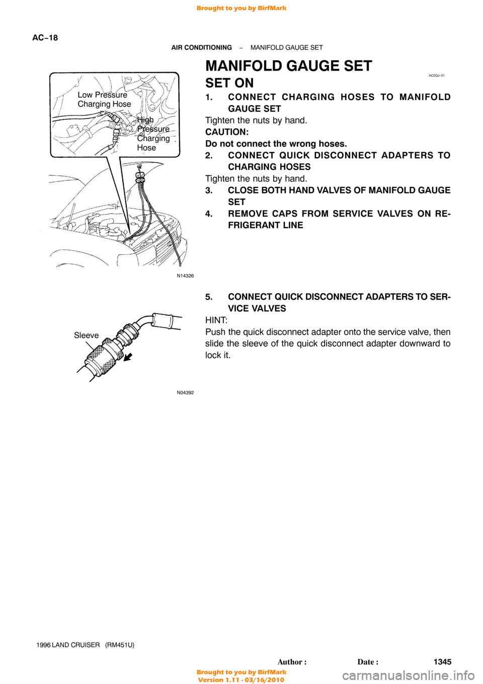
N14326
Low Pressure
Charging Hose
High
Pressure
Charging
Hose
AC2QJ−01
N04392
Sleeve
AC−18
−
AIR CONDITIONING MANIFOLD GAUGE SET
1345
Author�: Date�:
1996 LAND CRUISER (RM451U)
MANIFOLD GAUGE SET
SET ON
1. CONNECT CHARGING HOSES TO MANIFOLD
GAUGE SET
Tighten the nuts by hand.
CAUTION:
Do not connect the wrong hoses.
2. CONNECT QUICK DISCONNECT ADAPTERS TO CHARGING HOSES
Tighten the nuts by hand.
3. CLOSE BOTH HAND VALVES OF MANIFOLD GAUGE
SET
4. REMOVE CAPS FROM SERVICE VALVES ON RE- FRIGERANT LINE
5. CONNECT QUICK DISCONNECT ADAPTERS TO SER-
VICE VALVES
HINT:
Push the quick disconnect adapter onto the service valve, then
slide the sleeve of the quick disconnect adapter downward to
lock it.
Brought to you by BirfMark
Brought to you by BirfMark
Version 1.11 - 03/16/2010
Page 63 of 1399
AC2QM−01
AC−20
−
AIR CONDITIONING REFRIGERANT LINE
1347
Author�: Date�:
1996 LAND CRUISER (RM451U)
REFRIGERANT LINE
ON−VEHICLE INSPECTION
1. INSPECTION HOSE AND TUBE CONNECTIONS FOR LOOSENESS
2. INSPECT HOSES AND TUBES FOR LEAKAGE
Using a gas leak detector, check for leakage of refrigerant.
Brought to you by BirfMark
Brought to you by BirfMark
Version 1.11 - 03/16/2010
Page 71 of 1399

AC2QS−01
Z17942
Hose ”A”Hose ”B”
Z17943
Hose Clip
Heater
Radiator Pope Paint Mark
Water Hose Hose ”A”Upper
FR
RH Hose ”B”
RH
FR
Marking 45 ± 10° 45
°
10 °
N06494
AC−28
−
AIR CONDITIONING HEATER UNIT
1355
Author�: Date�:
1996 LAND CRUISER (RM451U)
HEATER UNIT
REMOVAL
1. REMOVE COOLING UNIT (See page AC−24)
2. DRAIN ENGINE COOLANT FROM RADIATOR
HINT:
It is not necessary to drain out all the coolant.
3. DISCONNECT WATER HOSES FROM HEATER RA- DIATOR PIPES
(a) Grip the claws of the hose clip with pliers and slide the clip
along the hose to a place where it does not clamp the
hose to the pipe.
(b) Disconnect the water hoses.
HINT:
�Push the water hose onto the heater radiator pipe as far
as the ridge on the pipe.
�Install the hose clip in a position, as shown in the illustra-
tion.
4. REMOVE PIPE GROMMETS
5. REMOVE INSTRUMENT PANEL SAFETY PAD (See page BO−76 )
6. REMOVE INSTRUMENT PANEL REINFORCEMENT
(See page BO−76 )
7. REMOVE HEATER UNIT
(a) Remove the 3 screws and defroster nozzle.(...~---------I I
I II II I
I II IIIv-
N02485
N18179N18181
Brought to you by BirfMark
Brought to you by BirfMark
Version 1.11 - 03/16/2010
Page 78 of 1399

DISASSEMBLY
1. RUN ENGINE AT IDLE SPEED WITH A/C SWITCH ON
FOR 10 M")
AC2R7−04
AC0943
SST
AC0944
SST
AC0945
SST
−
AIR CONDITIONING COMPRESSOR AND MAGNETIC CLUTCH
AC−35
1996 LAND CRUISER (RM451U)
DISASSEMBLY
1. RUN ENGINE AT IDLE SPEED WITH A/C SWITCH ON
FOR 10 MINUTES
2. STOP ENGINE
3. DISCONNECT NEGATIVE ( −) TERMINAL CABLE
FROM BATTERY
4. DISCHARGE REFRIGERANT FROM REFRIGERA TION
SYSTEM
5. DISCONNECT DISCHARGE AND SUCTION HOSES
Remove the 2 bolts and disconnect the both hoses.
NOTICE:
Cap the open fittings immediately to keep the moisture or
dirt out of the system.
6. REMOVE ENGINE UNDER COVER
7. REMOVE DRIVE BELT (See page AC−16)
8. REMOVE COMPRESSOR
(a) Disconnect the connector.
(b) Remove the 4 bolts and pull the compressor upward.
9. REMOVE COMPRESSOR (See page AC−35 )
10. REMOVE PRESSURE PLATE
(a) Using SST and a socket wrench, remove the shaft bolt. Torque: 13.2 N·m (135 kgf·cm, 9 ft·lbf)
SST 07112 −76060
(b) Install a SST on the pressure plate. SST 07112 −66040
(c) Using SST and a socket wrench, remove the pressure plate.
SST 07112 −76060
Brought to you by BirfMark
Brought to you by BirfMark
Version 1.11 - 03/16/2010
Page 81 of 1399

REASSEMBLY
1. INSTALL COMPRESSOR
(a) Install the compressor with the 4 bolts. Torque: 25 N·m")
AC2R8−01
N04963
AC−38
−
AIR CONDITIONING COMPRESSOR AND MAGNETIC CLUTCH
1996 LAND CRUISER (RM451U)
REASSEMBLY
1. INSTALL COMPRESSOR
(a) Install the compressor with the 4 bolts. Torque: 25 N·m (250 kgf·cm, 18 ft·lbf)
(b) Connect the connector.
2. CONNECT DISCHARGE AND SUCTION HOSES Torque: 10 N·m (100 kgf·cm, 7 ft·lbf)
NOTICE:
Hoses should be connected immediately after the caps
have been removed.
HINT:
Lubricate 2 new O −rings with compressor oil and install the
hoses.
3. INSTALL AND INSPECT DRIVE BELT (See page AC−17 )
4. INSTALL ENGINE UNDER COVER
5. CONNECT NEGATIVE ( −) TERMINAL CABLE TO BAT-
TERY
6. EVACUATE AIR FROM REFRIGERATION SYSTEM
7. CHARGE SYSTEM WITH REFRIGERANT AND IN- SPECT FOR LEAKAGE OF REFRIGERANT
Specified amount:
850 ± 50 g (29.98 ± 1.76 oz.)
Using a gas leak detector, check for leakage of refrigerant.
If there is leakage, check the tightening torque at the joints.
8. INSPECT A/C OPERATION
Reassembly is in the reverse order of disassembly (See
page AC−35 ).
9. CHECK CLEARANCE OF MAGNETIC CLUTCH
(a) Set the dial indicator to the pressure plate of the magnetic
clutch.
(b) Connect the magnetic clutch lead wire to the positive (+) terminal of the battery.
(c) Check the clearance between the pressure plate and ro- tor when connecting the negative ( −) terminal to the bat-
tery.
Standard clearance:
0.5 ± 0.15 mm (0.020 ± 0.0059 in.)
If the clearance is not within the standard clearance, adjust the
clearance using shims to obtain the standard clearance. Shim Thickness:
0.1 mm (0.004 in.)
0.3 mm (0.012 in.)
0.5 mm (0.020 in.)
Brought to you by BirfMark
Brought to you by BirfMark
Version 1.11 - 03/16/2010