Page 343 of 1399
BR1CI-01
R13497
R13591
BR-10
-
BRAKE BRAKE MASTER CYLINDER
1996 LAND CRUISER (RM451U)
REMOVAL
1. DISCONNECT LEVEL WARNING SWITCH CONNEC- TOR
2. TAKE OUT FLUID WITH SYRINGE
NOTICE:
Do not let brake fluid remain on a painted surface. Wash it
off immediately.
3. DISCONNECT BRAKE LINES
Using SST, disconnect the 4 brake lines from the master cylin-
der and 3-way. SST 09023-00100
Torque: 15 N´m (155 kgf´cm, 11 ft´lbf)
4. REMOVE MASTER CYLINDER
(a) Remove the 4 nuts. Torque: 13 N´m (130 kgf´cm, 9 ft´lbf)
(b) Remove the 3-way, check valve bracket, wire harness clamp and bracket.
(c) Pull out the master cylinder and gasket.
Brought to you by BirfMark
Brought to you by BirfMark
Version 1.11 - 03/16/2010
Page 344 of 1399

BR1CJ-01
R12236
A
-
BRAKE BRAKE MASTER CYLINDER
BR-1 1
1996 LAND CRUISER (RM451U)
DISASSEMBLY
1. REMOVE RESERVOIR
(a) Remove the set screw and pull out the reservoir.
Torque: 1.7 N´m (17.5 kgf´cm, 15.2 in.´lbf)
(b) Remove the cap and strainer from the reservoir.
2. REMOVE 2 GROMMETS
3. REMOVE BOLT AND CLAMP FROM CYLINDER BODY
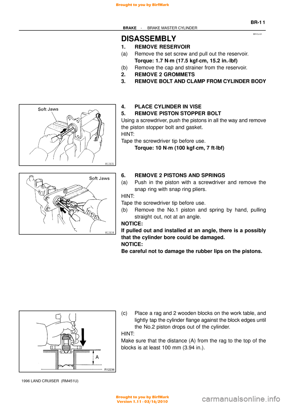
4. PLACE CYLINDER IN VISE
5. REMOVE PISTON STOPPER BOLT
Using a screwdriver, push the pistons in all the way and remove
the piston stopper bolt and gasket.
HINT:
Tape the screwdriver tip before use. Torque: 10 N´m (100 kgf´cm, 7 ft´lbf)
6. REMOVE 2 PISTONS AND SPRINGS
(a) Push in the piston with a screwdriver and remove the snap ring with snap ring pliers.
HINT:
Tape the screwdriver tip before use.
(b) Remove the No.1 piston and spring by hand, pulling straight out, not at an angle.
NOTICE:
If pulled out and installed at an angle, there is a possibly
that the cylinder bore could be damaged.
NOTICE:
Be careful not to damage the rubber lips on the pistons.
(c) Place a rag and 2 wooden blocks on the work table, and lightly tap the cylinder flange against the block edges until
the No.2 piston drops out of the cylinder.
HINT:
Make sure that the distance (A) from the rag to the top of the
blocks is at least 100 mm (3.94 in.).
Brought to you by BirfMark
Brought to you by BirfMark
Version 1.11 - 03/16/2010
Page 353 of 1399

BR1CQ−01
BR3976
SST
Gasket
R11347
SST
BR−20
−
BRAKE BRAKE BOOSTER ASSEMBLY
1996 LAND CRUISER (RM451U)
INSTALLATION
1. INSTALL BRAKE BOOSTER
(a) Install the booster and a new gasket.
(b) Install the clevis to the operating rod.
(c) Install and torque the booster installation nuts. Torque: 13 N·m (130 kgf·cm, 9 ft·lbf)
(d) Install the clevis pin into the clevis and brake pedal, and
install the clip to the clevis pin.
(e) Install the pedal return spring.
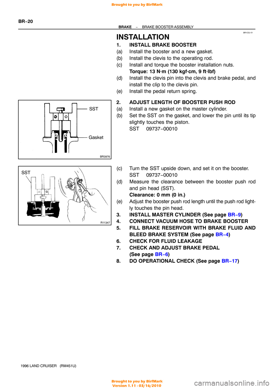
2. ADJUST LENGTH OF BOOSTER PUSH ROD
(a) Install a new gasket on the master cylinder.
(b) Set the SST on the gasket, and lower the pin until its tip slightly touches the piston.
SST 09737−00010
(c) Turn the SST upside down, and set it on the booster. SST 09737−00010
(d) Measure the clearance between the booster push rod and pin head (SST).
Clearance: 0 mm (0 in.)
(e) Adjust the booster push rod length until the push rod light-
ly touches the pin head.
3. INSTALL MASTER CYLINDER (See page BR−9 )
4. CONNECT VACUUM HOSE TO BRAKE BOOSTER
5. FILL BRAKE RESERVOIR WITH BRAKE FLUID AND
BLEED BRAKE SYSTEM (See page BR−4 )
6. CHECK FOR FLUID LEAKAGE
7. CHECK AND ADJUST BRAKE PEDAL (See page BR−6 )
8. DO OPERATIONAL CHECK (See page BR−17 )
Brought to you by BirfMark
Brought to you by BirfMark
Version 1.11 - 03/16/2010
Page 358 of 1399
BR1CU−03
−
BRAKE FRONT BRAKE CALIPER
BR−25
1996 LAND CRUISER (RM451U)
REMOVAL
1. DISCONNECT FLEXIBLE HOSE
(a) Remove the union bolt and 2 gaskets from the caliper,
then disconnect the flexible hose from the caliper.
Torque: 30 N·m (310 kgf·cm, 22 ft·lbf)
(b) Use a container to catch the brake fluid as it drains out.
2. REMOVE CALIPER
Remove the 2 mounting bolts and caliper. Torque: 123 N·m (1,250 kgf·cm, 90 ft·lbf)
3. REMOVE THESE PARTS:
�Clip
�2 pins
�Anti−rattle spring
�2 pads
�4 anti−squeal shims
Brought to you by BirfMark
Brought to you by BirfMark
Version 1.11 - 03/16/2010
Page 360 of 1399

BR1CX−03
BR0251
−
BRAKE FRONT BRAKE CALIPER
BR−27
1996 LAND CRUISER (RM451U)
INSPECTION
1. MEASURE PAD LINING THICKNESS
Using a ruler, measure the pad lining thickness.
Standard thickness: 9.5 mm (0.374 in.)
Minimum thickness: 1.0 mm (0.039 in.)
Replace the pad if the thickness is less than the minimum (the
1.0 mm slit is no longer visible), or if it shows signs of uneven
wear.
2. MEASURE DISC THICKNESS
Using a micrometer, measure the disc thickness. Standard thickness: 32.0 mm (1.260 in.)
Minimum thickness: 30.0 mm (1.181 in.)
If the disc is scored or worn, or if its thickness is less than the
minimum, repair or replace the disc.
3. MEASURE DISC RUNOUT
Using a dial indicator, measure the disc runout at a position 10
mm (0.39 in.) from the outside edge. Maximum disc runout: 0.15 mm (0.0059 in.)
If the runout is greater than the maximum, replace the disc or
grind it on a ”On−Car” brake lathe.
HINT:
Before measuring the runout, confirm that the front hub bearing
play is within the specification.
4. IF NECESSARY, REPLACE DISC
(a) Remove the front axle hub (See page SA−7).
(b) Remove the disc from the axle hub.
(c) Install a new disc and torque the bolts. Torque: 74 N·m (750 kgf·cm, 54 ft·lbf)
(d) Install the axle hub and adjust the front bearing preload (See page SA−9 ).
Brought to you by BirfMark
Brought to you by BirfMark
Version 1.11 - 03/16/2010
Page 365 of 1399
BR−32
−
BRAKE REAR BRAKE PAD
1996 LAND CRUISER (RM451U)
(a) Install pad wear indicator plate to each pads.
(b) Install the anti−squeal shim to the outer pad.
(c) Install the 2 pads so the wear indicator plate is facing up-
ward.
NOTICE:
Do not allow oil or grease to get on the rubbing face.
8. INSTALL CALIPER
(a) Draw out a small amount of brake fluid from the reservoir.
(b) Press in piston with a hammer handle or an equivalent.
HINT:
Always change the pads on one wheel at a time as there is a
possibility of the opposite piston flying out.
(c) Install the caliper carefully so the boot is not wedged.
(d) Install and torque the sliding main pin and sub pin. Torque: 88 N·m (900 kgf·cm, 65 ft·lbf)
9. INSTALL REAR WHEEL
10. CHECK THAT FLUID LEVEL IS AT MAX LINE
Brought to you by BirfMark
Brought to you by BirfMark
Version 1.11 - 03/16/2010
Page 367 of 1399
BR1D2−01
BR−34
−
BRAKE REAR BRAKE CALIPER
1996 LAND CRUISER (RM451U)
REMOVAL
1. DISCONNECT FLEXIBLE HOSE
(a) Remove the union bolt and 2 gaskets from the caliper, then disconnect the flexible hose from the cali-
per.
Torque: 30 N·m (310 kgf·cm, 22 ft·lbf)
(b) Use a container to catch the brake fluid as it drains out.
2. REMOVE CALIPER
Remove the 2 sliding pins and caliper. Torque: 88 N·m (900 kgf·cm, 65 ft·lbf)
3. REMOVE THESE PARTS:
(a) 2 pads with anti −squeal shim
(b) 4 pad support plates
Brought to you by BirfMark
Brought to you by BirfMark
Version 1.11 - 03/16/2010
Page 369 of 1399
BR1D5−03
BR−36
−
BRAKE REAR BRAKE CALIPER
1996 LAND CRUISER (RM451U)
INSPECTION
1. MEASURE PAD LINING THICKNESS (See step 1. on page BR−27)
Standard thickness: 10.0 mm (0.394 in.)
Minimum thickness: 1.0 mm (0.039 in.)
2. MEASURE DISC THICKNESS (See page BR−27 )
Standard thickness: 18.0 mm (0.709 in.)
Minimum thickness: 16.0 mm (0.630 in.)
3. MEASURE DISC RUNOUT (See page BR−27 )
Maximum disc runout: 0.15 mm (0.0059 in.)
If the runout is greater than the maximum, adjust the disc runout
or grind it on a ”On−Car” brake lathe.
4. IF NECESSARY, REPLACE DISC
(a) Remove the torque plate..
(b) Remove the hub nuts of the temporarily installed disc and
pull off the disc.
(c) Install a new disc and and loosely install the hub nuts.
(d) Install the torque plate and tighten the mounting bolts. Torque: 103 N·m (1,050 kgf·cm, 76 ft·lbf)
Brought to you by BirfMark
Brought to you by BirfMark
Version 1.11 - 03/16/2010