Page 1137 of 1399

SA2395
SST
Z06903
SST
Z06904
SST
R13238
SST
SA1966
SST
SA−74
−
SUSPENSION AND AXLE REAR DIFFERENTIAL FRONT OIL SEAL
1996 LAND CRUISER (RM451U)
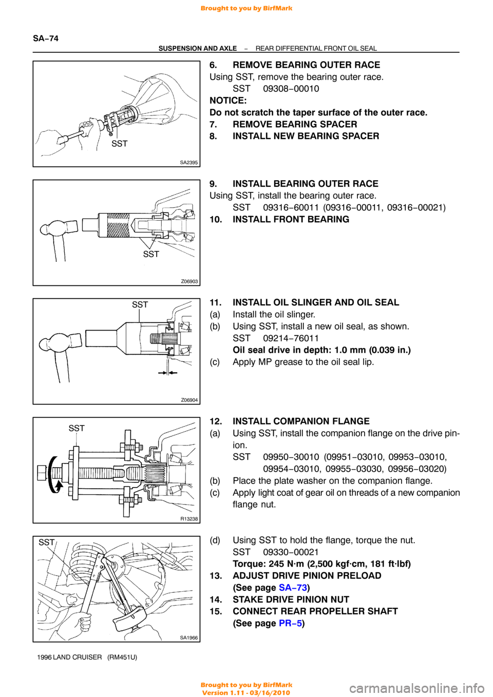
6. REMOVE BEARING OUTER RACE
Using SST, remove the bearing outer race.
SST 09308−00010
NOTICE:
Do not scratch the taper surface of the outer race.
7. REMOVE BEARING SPACER
8. INSTALL NEW BEARING SPACER
9. INSTALL BEARING OUTER RACE
Using SST, install the bearing outer race. SST 09316−60011 (09316 −00011, 09316−00021)
10. INSTALL FRONT BEARING
11. INSTALL OIL SLINGER AND OIL SEAL
(a) Install the oil slinger.
(b) Using SST, install a new oil seal, as shown. SST 09214−76011
Oil seal drive in depth: 1.0 mm (0.039 in.)
(c) Apply MP grease to the oil seal lip.
12. INSTALL COMPANION FLANGE
(a) Using SST, install the companion flange on the drive pin- ion.
SST 09950−30010 (09951 −03010, 09953−03010,
09954 −03010, 09955 −03030, 09956−03020)
(b) Place the plate washer on the companion flange.
(c) Apply light coat of gear oil on threads of a new companion
flange nut.
(d) Using SST to hold the flange, torque the nut. SST 09330−00021
Torque: 245 N·m (2,500 kgf·cm, 181 ft·lbf)
13. ADJUST DRIVE PINION PRELOAD (See page SA−73 )
14. STAKE DRIVE PINION NUT
15. CONNECT REAR PROPELLER SHAFT (See page PR−5 )
Brought to you by BirfMark
Brought to you by BirfMark
Version 1.11 - 03/16/2010
Page 1160 of 1399

SA2454
SST
R13414
SST
SA2351
SST
SA2446
−
SUSPENSION AND AXLE REAR DIFFERENTIAL CARRIER
SA−97
1996 LAND CRUISER (RM451U)
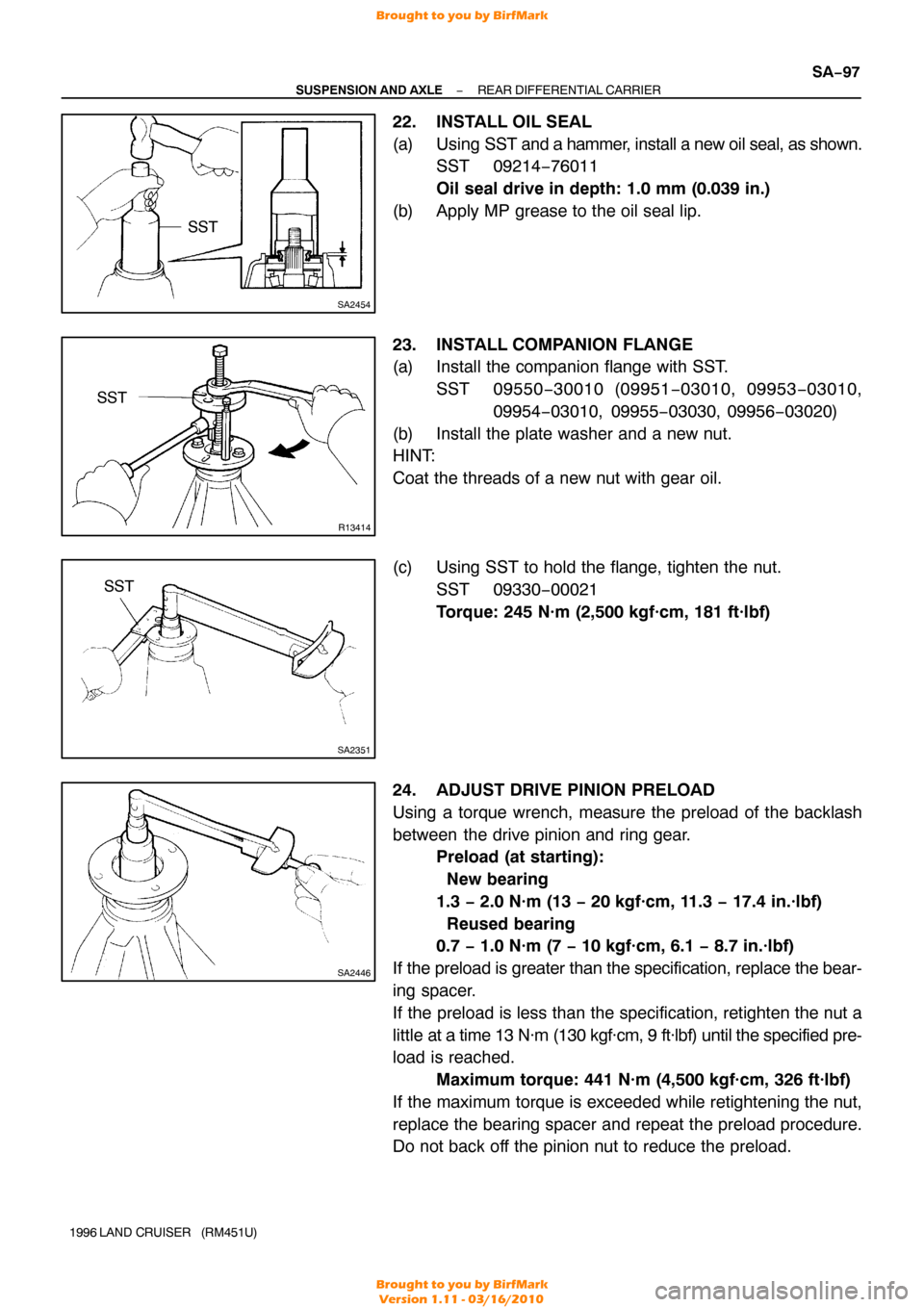
22. INSTALL OIL SEAL
(a) Using SST and a hammer, install a new oil seal, as shown.
SST 09214−76011
Oil seal drive in depth: 1.0 mm (0.039 in.)
(b) Apply MP grease to the oil seal lip.
23. INSTALL COMPANION FLANGE
(a) Install the companion flange with SST. SST 09550 −30010 (09951 −03010, 09953 −03010,
09954 −03010, 09955 −03030, 09956−03020)
(b) Install the plate washer and a new nut.
HINT:
Coat the threads of a new nut with gear oil.
(c) Using SST to hold the flange, tighten the nut. SST 09330−00021
Torque: 245 N·m (2,500 kgf·cm, 181 ft·lbf)
24. ADJUST DRIVE PINION PRELOAD
Using a torque wrench, measure the preload of the backlash
between the drive pinion and ring gear. Preload (at starting):
New bearing
1.3 − 2.0 N·m (13 − 20 kgf·cm, 11.3 − 17.4 in.·lbf)
Reused bearing
0.7 − 1.0 N·m (7 − 10 kgf·cm, 6.1 − 8.7 in.·lbf)
If the preload is greater than the specification, replace the bear-
ing spacer.
If the preload is less than the specification, retighten the nut a
little at a time 13 N·m (130 kgf·cm, 9 ft·lbf) until the specified pre-
load is reached. Maximum torque: 441 N·m (4,500 kgf·cm, 326 ft·lbf)
If the maximum torque is exceeded while retightening the nut,
replace the bearing spacer and repeat the preload procedure.
Do not back off the pinion nut to reduce the preload.
Brought to you by BirfMark
Brought to you by BirfMark
Version 1.11 - 03/16/2010
Page 1331 of 1399

SS1EC−02
SS−30
−
SERVICE SPECIFICATIONS SUSPENSION AND AXLE
153
Author�: Date�:
1996 LAND CRUISER (RM451U)
SUSPENSION AND AXLE
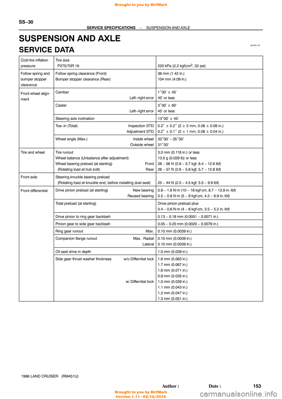
SERVICE DATA
Cold tire inflation
pressureTire size
P275/70R 16
220 kPa (2.2 kgf/cm2, 32 psi)
Follow spring and
bumper stopper
clearanceFollow spring clearance (Front)
Bumper stopper clearance (Rear)36 mm (1.42 in.)
104 mm (4.09 in.)
Front wheel align-
mentCamber Left−right error1°00’ ± 45’
45’ or less
Caster Left−right error3°00’ ± 60’
45’ or less
Steering axis inclination13 °00’ ± 45’
To e −in (Total) Inspection STD
Adjustment STD0.2 ° ± 0.2° (2 ± 2 mm, 0.08 ± 0.08 in.)
0.2 ° ± 0.1° (2 ± 1 mm, 0.08 ± 0.04 in.)
Wheel angle (Max.) Inside wheel
Outside wheel32 °00’ − 35°00’
31 °00’
Tire and wheelTire runout
Wheel balance (Unbalance after adjustment)
Wheel bearing preload (at starting) Front
(Rotating load at hub bolt) Rear3.0 mm (0.118 in.) or less
13.0 g (0.029 lb) or less
28 − 56 N (2.9 − 5.7 kgf, 6.4 − 12.6 lbf)
26 − 57 N (2.6 − 5.8 kgf, 5.7 − 12.8 lbf)
Front axleSteering knuckle bearing preload
(Rotating load at knuckle end, before installing dust seal)
25 − 44 N (2.5 − 4.5 kgf, 5.5 − 9.9 lbf)
Front dif ferentialDrive pinion preload (at starting) New bearing
Reused bearing0.9 − 1.6 N·m (10 − 16 kgf·cm, 8.7 − 13.9 in.·lbf)
0.5 − 0.8 N·m (5 − 8 kgf·cm, 4.3 − 6.9 in.·lbf)
Total preload (at starting)Drive pinion preload plus
0.4 − 0.6 N·m (4 − 6 kgf·cm, 3.5 − 5.2 in.·lbf)
Drive pinion to ring gear backlash0.13 − 0.18 mm (0.0051 − 0.0071 in.)
Pinion gear to side gear backlash0.05 − 0.20 mm (0.0020 − 0.0079 in.)
Ring gear runout Max.0.10 mm (0.0039 in.)
Companion flange runoutMax. Radial
Lateral0.10 mm (0.0039 in.)
0.10 mm (0.0039 in.)
Oil seal drive in depth1.0 mm (0.039 in.)
Side gear thrust washer thickness w/o Differntial lock
w/ Differntial lock1.6 mm (0.063 in.)
1.7 mm (0.067 in.)
1.8 mm (0.071 in.)
0.9 mm (0.035 in.)
1.0 mm (0.039 in.)
1.1 mm (0.043 in.)
1.2 mm (0.047 in.)
1.3 mm (0.051 in.)
Brought to you by BirfMark
Brought to you by BirfMark
Version 1.11 - 03/16/2010
Page 1332 of 1399

−
SERVICE SPECIFICATIONS SUSPENSION AND AXLE
SS−31
154
Author�: Date�:
1996 LAND CRUISER (RM451U)
Front dif
ferential
(cont’d)
Drive pinion adjusting plate washer thickness1.70 mm (0.0669 in.)
1.73 mm (0.0681 in.)
1.76 mm (0.0693 in.)
1.79 mm (0.0705 in.)
1.82 mm (0.0717 in.)
1.85 mm (0.0728 in.)
1.88 mm (0.0740 in.)
1.91 mm (0.0752 in.)
1.94 mm (0.0764 in.)
1.97 mm (0.0776 in.)
2.00 mm (0.0787 in.)
2.03 mm (0.0799 in.)
2.06 mm (0.0811 in.)
2.09 mm (0.0823 in.)
2.12 mm (0.0835 in.)
2.15 mm (0.0846 in.)
2.18 mm (0.0858 in.)
2.21 mm (0.0870 in.)
2.24 mm (0.0882 in.)
2.27 mm (0.0894 in.)
2.30 mm (0.0906 in.)
2.33 mm (0.0917 in.)
Rear dif ferentialDrive pinion preload (at starting) New bearing
Reused bearing1.3 − 2.0 N·m (13 − 20 kgf·cm, 11.3 − 17.4 in.·lbf)
0.7 − 1.0 N·m (7 − 10 kgf·cm, 6.1 − 8.7 in.·lbf)
Total preload (at starting)
w/o Differntial lockw/ Differntial lockDrive pinion preload plus
0.4 − 0.6 N·m (4 − 6 kgf·cm, 3.5 − 5.2 in.·lbf)
0.3 − 0.7 N·m (3 − 7 kgf·cm, 2.6 − 6.1 in.·lbf)
Drive pinion to ring gear backlash0.15 − 0.20 mm (0.0059 − 0.0079 in.)
Pinion gear to side gear backlash0.02 − 0.20 mm (0.0008 − 0.0079 in.)
Ring gear runout Max.0.10 mm (0.0039 in.)
Companion flange runoutMax. Radial
Lateral0.10 mm (0.0039 in.)
0.10 mm (0.0039 in.)
Oil seal drive in depth1.0 mm (0.039 in.)
Side gear thrust washer thickness1.60 mm (0.0630 in.)
1.75 mm (0.0689 in.)
1.90 mm (0.0748 in.)
2.05 mm (0.0807 in.)
Drive pinion adjusting plate washer thickness1.05 mm (0.0413 in.)
1.10 mm (0.0433 in.)
1.15 mm (0.0453 in.)
1.20 mm (0.0472 in.)
1.25 mm (0.0492 in.)
1.30 mm (0.0512 in.)
1.35 mm (0.0531 in.)
1.40 mm (0.0551 in.)
1.45 mm (0.0571 in.)
1.50 mm (0.0591 in.)
1.55 mm (0.0610 in.)
Brought to you by BirfMark
Brought to you by BirfMark
Version 1.11 - 03/16/2010