Page 2040 of 2890
B2M0576A
3) Turn ignition switch to OFF.
4) Disconnect connector from idle air control solenoid
valve.
5) Turn ignition switch to ON.
6) Measure voltage between ECM and chassis ground.
: Connector & terminal
(B84) No. 13 (+)—Chassis ground (�):
Is the voltage more than 10 V?
: Repair short circuit in harness between ECM and
idle air control solenoid valve connector.
: Go to next.
: Connector & terminal
(B84) No. 14 (+)—Chassis ground (�):
Is the voltage more than 10 V?
: Repair short circuit in harness between ECM and
idle air control solenoid valve connector and
replace ECM.
: Go to next.
: Is there poor contact in ECM connector?
: Repair poor contact in ECM connector.
: Go to step10AN3.
272
2-7ON-BOARD DIAGNOSTICS II SYSTEM
10. Diagnostics Chart with Trouble Code
Page 2042 of 2890

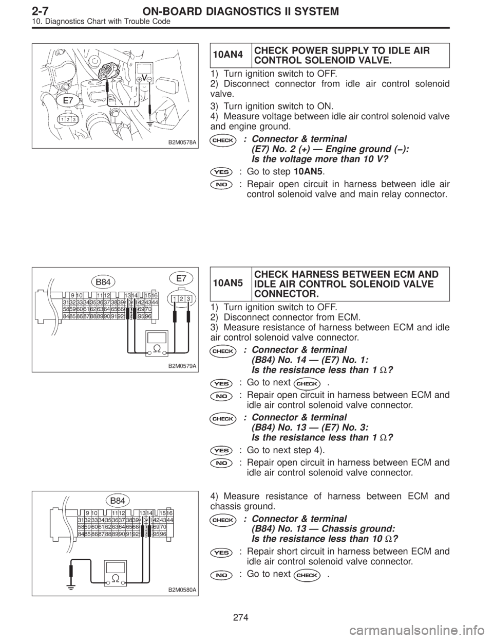
B2M0578A
10AN4CHECK POWER SUPPLY TO IDLE AIR
CONTROL SOLENOID VALVE.
1) Turn ignition switch to OFF.
2) Disconnect connector from idle air control solenoid
valve.
3) Turn ignition switch to ON.
4) Measure voltage between idle air control solenoid valve
and engine ground.
: Connector & terminal
(E7) No. 2 (+)—Engine ground (�):
Is the voltage more than 10 V?
: Go to step10AN5.
: Repair open circuit in harness between idle air
control solenoid valve and main relay connector.
B2M0579A
10AN5CHECK HARNESS BETWEEN ECM AND
IDLE AIR CONTROL SOLENOID VALVE
CONNECTOR.
1) Turn ignition switch to OFF.
2) Disconnect connector from ECM.
3) Measure resistance of harness between ECM and idle
air control solenoid valve connector.
: Connector & terminal
(B84) No. 14—(E7) No. 1:
Is the resistance less than 1Ω?
: Go to next.
: Repair open circuit in harness between ECM and
idle air control solenoid valve connector.
: Connector & terminal
(B84) No. 13—(E7) No. 3:
Is the resistance less than 1Ω?
: Go to next step 4).
: Repair open circuit in harness between ECM and
idle air control solenoid valve connector.
B2M0580A
4) Measure resistance of harness between ECM and
chassis ground.
: Connector & terminal
(B84) No. 13—Chassis ground:
Is the resistance less than 10Ω?
: Repair short circuit in harness between ECM and
idle air control solenoid valve connector.
: Go to next.
274
2-7ON-BOARD DIAGNOSTICS II SYSTEM
10. Diagnostics Chart with Trouble Code
Page 2043 of 2890
: Connector & terminal
(B84) No. 14—Chassis ground:
Is the resistance less than 10Ω?
: Repair short circuit in harness between ECM and
idle air control solenoid valve connector.
: Go to next.
: Is there poor contact in idle air control sole-
noid valve connector?
: Repair poor contact in idle air control solenoid
valve connector.
: Contact with SOA service.
NOTE:
Inspection by DTM is required, because probable cause is
deterioration of multiple parts.
275
2-7ON-BOARD DIAGNOSTICS II SYSTEM
10. Diagnostics Chart with Trouble Code
Page 2048 of 2890
B2M0582A
10AQ1CHECK HARNESS BETWEEN ECM AND
DATA LINK CONNECTOR.
1) Turn ignition switch to OFF.
2) Disconnect connector from ECM.
3) Measure resistance of harness between ECM and data
link connector (for Subaru Select Monitor & OBD-II general
scan tool).
: Connector & terminal
(B84) No. 93—(B40) No. 10:
Is the resistance less than 1Ω?
: Go to next step 4).
: Repair open circuit in harness between ECM and
data link connector.
B2M0583A
4) Measure resistance of harness between ECM and
chassis ground.
: Connector & terminal
(B84) No. 93—Chassis ground:
Is the resistance less than 10Ω?
: Repair short circuit in harness between ECM and
data link connector.
: Repair poor contact in ECM connector and data
link connector.
280
2-7ON-BOARD DIAGNOSTICS II SYSTEM
10. Diagnostics Chart with Trouble Code
Page 2052 of 2890

10AS1
CHECK OPERATION OF BRAKE LIGHT.
: Does brake light come on when depressing
the brake pedal?
: Go to step10AS2.
: Repair or replace brake light circuit.
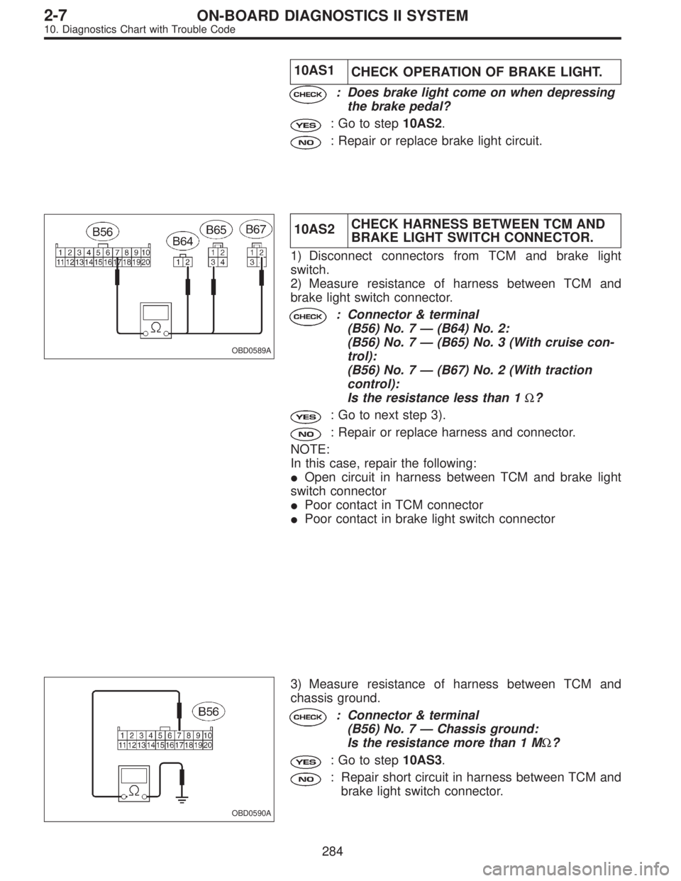
OBD0589A
10AS2CHECK HARNESS BETWEEN TCM AND
BRAKE LIGHT SWITCH CONNECTOR.
1) Disconnect connectors from TCM and brake light
switch.
2) Measure resistance of harness between TCM and
brake light switch connector.
: Connector & terminal
(B56) No. 7—(B64) No. 2:
(B56) No. 7—(B65) No. 3 (With cruise con-
trol):
(B56) No. 7—(B67) No. 2 (With traction
control):
Is the resistance less than 1Ω?
: Go to next step 3).
: Repair or replace harness and connector.
NOTE:
In this case, repair the following:
�Open circuit in harness between TCM and brake light
switch connector
�Poor contact in TCM connector
�Poor contact in brake light switch connector
OBD0590A
3) Measure resistance of harness between TCM and
chassis ground.
: Connector & terminal
(B56) No. 7—Chassis ground:
Is the resistance more than 1 MΩ?
: Go to step10AS3.
: Repair short circuit in harness between TCM and
brake light switch connector.
284
2-7ON-BOARD DIAGNOSTICS II SYSTEM
10. Diagnostics Chart with Trouble Code
Page 2053 of 2890
OBD0588A
10AS3
CHECK INPUT SIGNAL FOR TCM.
1) Connect connectors to TCM and brake light switch.
2) Measure voltage between TCM and chassis ground.
: Connector & terminal
(B56) No. 7 (+)—Chassis ground (�):
Is the voltage less than 1 V when releasing
the brake pedal?
: Go to next.
: Adjust or replace brake light switch.
OBD0588A
: Connector & terminal
(B56) No. 7 (+)—Chassis ground (�):
Is the voltage more than 10 V when
depressing the brake pedal?
: Go to next.
: Adjust or replace brake light switch.
: Is there poor contact in TCM connector?
: Repair poor contact in TCM connector.
: Replace TCM.
285
2-7ON-BOARD DIAGNOSTICS II SYSTEM
10. Diagnostics Chart with Trouble Code
Page 2057 of 2890

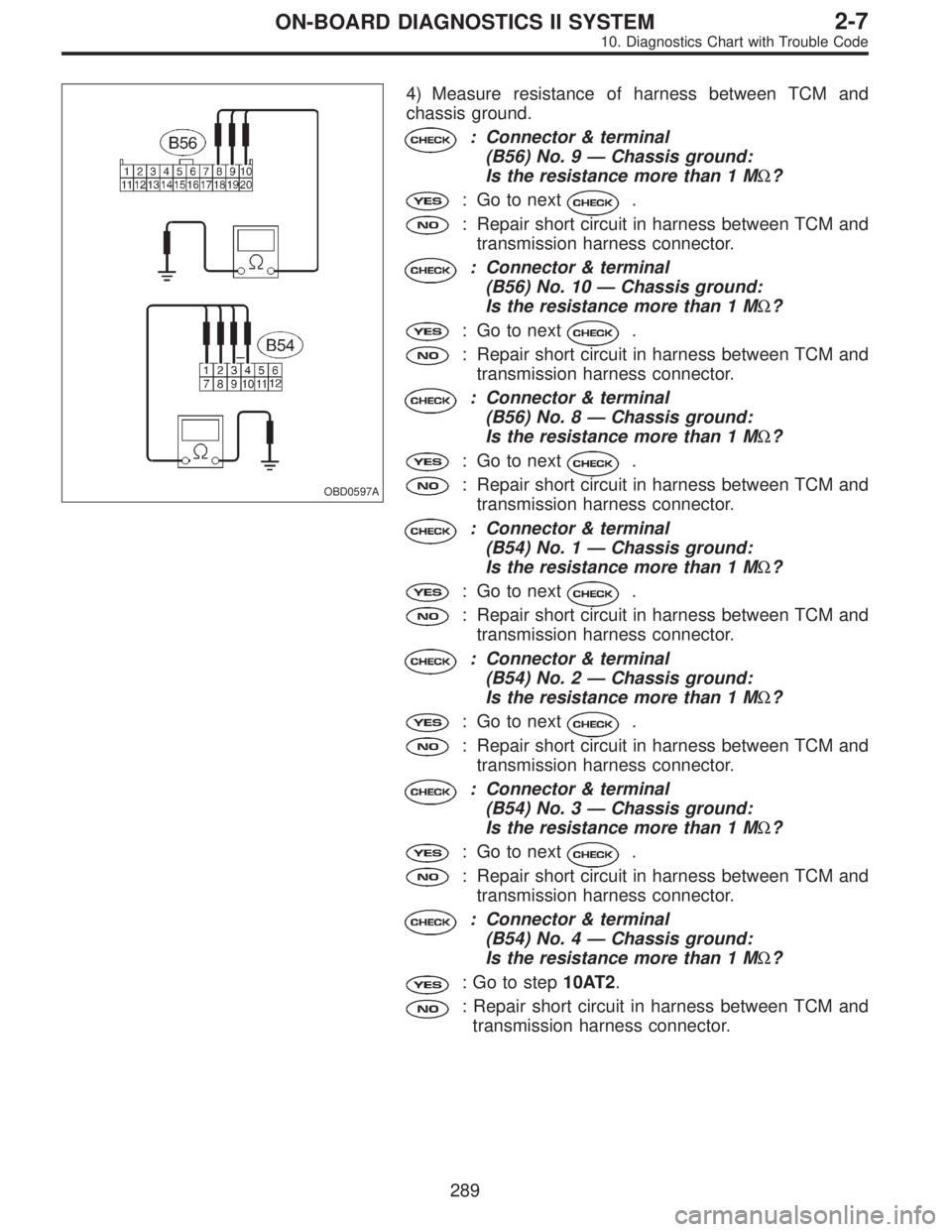
OBD0597A
4) Measure resistance of harness between TCM and
chassis ground.
: Connector & terminal
(B56) No. 9—Chassis ground:
Is the resistance more than 1 MΩ?
: Go to next.
: Repair short circuit in harness between TCM and
transmission harness connector.
: Connector & terminal
(B56) No. 10—Chassis ground:
Is the resistance more than 1 MΩ?
: Go to next.
: Repair short circuit in harness between TCM and
transmission harness connector.
: Connector & terminal
(B56) No. 8—Chassis ground:
Is the resistance more than 1 MΩ?
: Go to next.
: Repair short circuit in harness between TCM and
transmission harness connector.
: Connector & terminal
(B54) No. 1—Chassis ground:
Is the resistance more than 1 MΩ?
: Go to next.
: Repair short circuit in harness between TCM and
transmission harness connector.
: Connector & terminal
(B54) No. 2—Chassis ground:
Is the resistance more than 1 MΩ?
: Go to next.
: Repair short circuit in harness between TCM and
transmission harness connector.
: Connector & terminal
(B54) No. 3—Chassis ground:
Is the resistance more than 1 MΩ?
: Go to next.
: Repair short circuit in harness between TCM and
transmission harness connector.
: Connector & terminal
(B54) No. 4—Chassis ground:
Is the resistance more than 1 MΩ?
: Go to step10AT2.
: Repair short circuit in harness between TCM and
transmission harness connector.
289
2-7ON-BOARD DIAGNOSTICS II SYSTEM
10. Diagnostics Chart with Trouble Code
Page 2059 of 2890

: Connector & terminal
(T3) No. 6—No. 4
�Is the resistance less than 1Ωin“2”
position?
�Is the resistance more than 1 MΩin other
positions?
: Go to next.
:Goto.
: Connector & terminal
(T3) No. 5—No. 4
�Is the resistance less than 1Ωin“1”
position?
�Is the resistance more than 1 MΩin other
positions?
: Go to step10AT3.
:Goto.
: Is there faulty connection in the selector
cable?
: Repair connection of selector cable.
: Replace inhibitor switch.
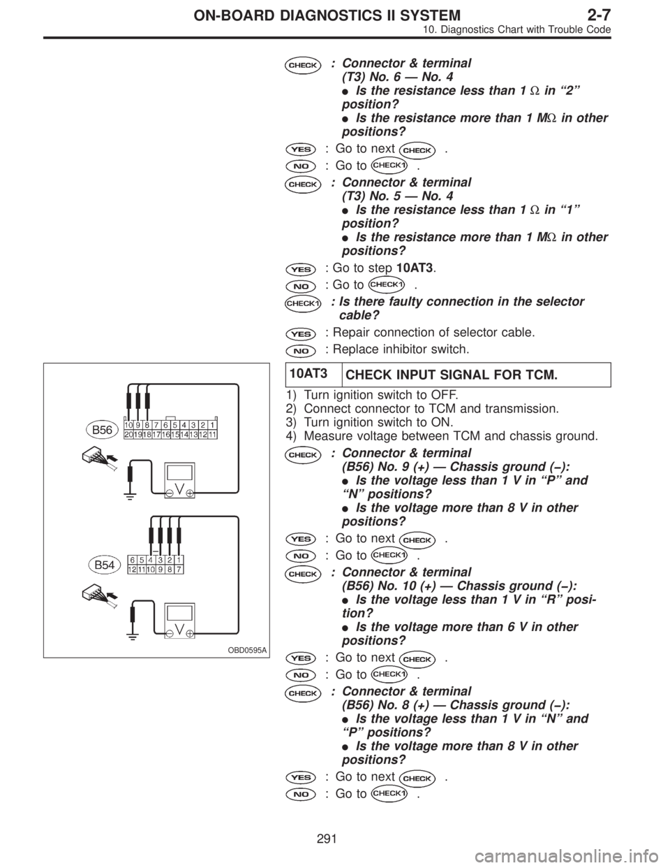
OBD0595A
10AT3
CHECK INPUT SIGNAL FOR TCM.
1) Turn ignition switch to OFF.
2) Connect connector to TCM and transmission.
3) Turn ignition switch to ON.
4) Measure voltage between TCM and chassis ground.
: Connector & terminal
(B56) No. 9 (+)—Chassis ground (�):
�Is the voltage less than1Vin“P”and
“N”positions?
�Is the voltage more than8Vinother
positions?
: Go to next.
:Goto.
: Connector & terminal
(B56) No. 10 (+)—Chassis ground (�):
�Is the voltage less than1Vin“R”posi-
tion?
�Is the voltage more than6Vinother
positions?
: Go to next.
:Goto.
: Connector & terminal
(B56) No. 8 (+)—Chassis ground (�):
�Is the voltage less than1Vin“N”and
“P”positions?
�Is the voltage more than8Vinother
positions?
: Go to next.
:Goto.
291
2-7ON-BOARD DIAGNOSTICS II SYSTEM
10. Diagnostics Chart with Trouble Code