Page 1962 of 2890
 Turn ignition switch to OFF.
2) Remove access hole lid.
3) Disconnect connector from fuel pump.
4) Turn ignition swi")
G2M0340
10Q3CHECK HARNESS BETWEEN FUEL TEM-
PERATURE SENSOR AND ECM CON-
NECTOR.
1) Turn ignition switch to OFF.
2) Remove access hole lid.
3) Disconnect connector from fuel pump.
4) Turn ignition switch to ON.
B2M0917A
5) Measure voltage between fuel pump connector and
chassis ground.
: Connector & terminal
(R58) No. 6 (+)—Chassis ground (�):
Is the voltage more than 4 V?
: Go to next step 6).
: Repair harness and connector.
NOTE:
In this case, repair the following:
�Open circuit in harness between ECM and fuel pump
connector
�Poor contact in fuel pump connector
�Poor contact in ECM connector
�Poor contact in coupling connectors (B98 (LHD)/B97
(RHD), and R57)
B2M0918A
6) Turn ignition switch to OFF.
7) Measure resistance of harness between fuel pump con-
nector and chassis ground.
: Connector & terminal
(R58) No. 5—Chassis ground:
Is the resistance less than 5Ω?
: Replace fuel temperature sensor.
: Repair harness and connector.
NOTE:
In this case, repair the following:
�Open circuit in harness between ECM and fuel pump
connector
�Poor contact in fuel pump connector
�Poor contact in ECM connector
�Poor contact in coupling connectors (B22, B98 (LHD)/
B97 (RHD), and R57)
194
2-7ON-BOARD DIAGNOSTICS II SYSTEM
10. Diagnostics Chart with Trouble Code
Page 1968 of 2890
 Turn ignition switch to ON.
2) Measure voltage between ECM connector and chassis
ground on faulty cylinders.
: Connector & terminal
#1 (B84) No. 96 (+)�")
B2M0556A
10V1
CHECK OUTPUT SIGNAL FROM ECM.
1) Turn ignition switch to ON.
2) Measure voltage between ECM connector and chassis
ground on faulty cylinders.
: Connector & terminal
#1 (B84) No. 96 (+)—Chassis ground (�):
#2 (B84) No. 70 (+)—Chassis ground (�):
#3 (B84) No. 44 (+)—Chassis ground (�):
#4 (B84) No. 16 (+)—Chassis ground (�):
Is the voltage more than 10 V?
: Go to step10V2.
: Go to step10V3.
B2M0556A
10V2CHECK HARNESS BETWEEN FUEL
INJECTOR AND ECM CONNECTOR.
1) Turn ignition switch to OFF.
2) Disconnect connector from fuel injector on faulty cylin-
der.
3) Turn ignition switch to ON.
4) Measure voltage between ECM connector and chassis
ground on faulty cylinders.
: Connector & terminal
#1 (B84) No. 96 (+)—Chassis ground (�):
#2 (B84) No. 70 (+)—Chassis ground (�):
#3 (B84) No. 44 (+)—Chassis ground (�):
#4 (B84) No. 16 (+)—Chassis ground (�):
Is the voltage more than 10 V?
: Repair short circuit in harness between ECM and
fuel injector. After repair, replace ECM.
: Go to next step 5).
G2M0464
5) Turn ignition switch to OFF.
6) Measure resistance between fuel injector terminals on
faulty cylinder.
: Terminals
No. 1—No.2:
Is the resistance less than 1Ω?
: Replace faulty fuel injector and ECM.
: Go to next.
200
2-7ON-BOARD DIAGNOSTICS II SYSTEM
10. Diagnostics Chart with Trouble Code
Page 1981 of 2890
 Turn ignition switch to OFF.
2) Disconnect connector from ECM.
3) Measure resistance between ECM harness connector
and chassis gr")
B2M0560A
10AA1CHECK HARNESS BETWEEN KNOCK
SENSOR AND ECM CONNECTOR.
1) Turn ignition switch to OFF.
2) Disconnect connector from ECM.
3) Measure resistance between ECM harness connector
and chassis ground.
: Connector & terminal
(B84) No. 3—Chassis ground:
Is the resistance more than 700 kΩ?
: Go to step10AA2.
: Go to next.
B2M0560A
: Connector & terminal
(B84) No. 3—Chassis ground:
Is the resistance less than 400 kΩ?
: Go to step10AA3.
: Go to step10AA4.
B2M0244A
10AA2
CHECK KNOCK SENSOR.
1) Disconnect connector from knock sensor.
2) Measure resistance between knock sensor connector
terminal and engine ground.
: Terminal
No. 1—Engine ground:
Is the resistance more than 700 kΩ?
: Go to next.
: Repair harness and connector.
NOTE:
In this case, repair the following:
�Open circuit in harness between knock sensor and ECM
connector
�Poor contact in knock sensor connector
�Poor contact in coupling connector (B21)
: Is the knock sensor installation bolt tight-
ened securely?
: Replace knock sensor.
: Tighten knock sensor installation bolt securely.
213
2-7ON-BOARD DIAGNOSTICS II SYSTEM
10. Diagnostics Chart with Trouble Code
Page 1982 of 2890
 Disconnect connector from knock sensor.
2) Measure resistance between knock sensor connector
terminal and engine ground.
: Terminal
No. 1—Engine ground:
Is the")
B2M0244A
10AA3
CHECK KNOCK SENSOR.
1) Disconnect connector from knock sensor.
2) Measure resistance between knock sensor connector
terminal and engine ground.
: Terminal
No. 1—Engine ground:
Is the resistance less than 400 kΩ?
: Replace knock sensor.
: Repair short circuit in harness between knock
sensor connector and ECM connector.
NOTE:
The harness between both connectors is shielded. Repair
short circuit of harness together with shield.
B2M0561A
10AA4
CHECK INPUT SIGNAL FOR ECM.
1) Connect connectors to ECM and knock sensor.
2) Turn ignition switch to ON.
3) Measure voltage between ECM and chassis ground.
: Connector & terminal
(B84) No. 3 (+)—Chassis ground (�):
Is the voltage more than 2 V?
: Even if MIL lights up, the circuit has returned to a
normal condition at this time. (However, the pos-
sibility of poor contact still remains.)
NOTE:
In this case, repair the following:
�Poor contact in knock sensor connector
�Poor contact in ECM connector
�Poor contact in coupling connector (B21)
: Repair poor contact in ECM connector.
214
2-7ON-BOARD DIAGNOSTICS II SYSTEM
10. Diagnostics Chart with Trouble Code
Page 1998 of 2890
10AE1
CHECK TRANSMISSION TYPE.
: Is transmission type AT?
: Go to step10AE2.
: Check AT/MT identification circuit.
[T10BW0].>
B2M0566A
10AE2
CHECK OUTPUT SIGNAL FROM ECM.
1) Turn ignition switch to ON.
2) Measure voltage between ECM and chassis ground.
: Connector & terminal
(B84) No. 71 (+)—Chassis ground (�):
Is the voltage more than 10 V?
: Go to step10AE3.
: Go to step10AE4.
B2M0566A
10AE3CHECK HARNESS BETWEEN EGR
SOLENOID VALVE AND ECM CONNEC-
TOR.
1) Turn ignition switch to OFF.
2) Disconnect connector from EGR solenoid valve.
3) Turn ignition switch to ON.
4) Measure voltage between ECM and chassis ground.
: Connector & terminal
(B84) No. 71 (+)—Chassis ground (�):
Is the voltage more than 10 V?
: Repair short circuit in harness and replace ECM.
NOTE:
The harness between ECM and EGR solenoid valve is in
short circuit.
: Go to next step 5).
230
2-7ON-BOARD DIAGNOSTICS II SYSTEM
10. Diagnostics Chart with Trouble Code
Page 2013 of 2890
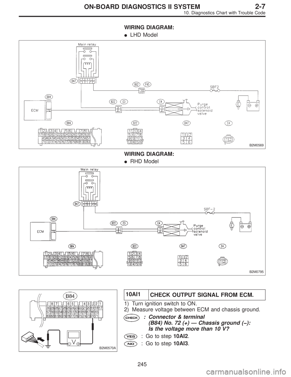
WIRING DIAGRAM:
�LHD Model
B2M0569
WIRING DIAGRAM:
�RHD Model
B2M0795
B2M0570A
10AI1
CHECK OUTPUT SIGNAL FROM ECM.
1) Turn ignition switch to ON.
2) Measure voltage between ECM and chassis ground.
: Connector & terminal
(B84) No. 72 (+)—Chassis ground (�):
Is the voltage more than 10 V?
: Go to step10AI2.
: Go to step10AI3.
245
2-7ON-BOARD DIAGNOSTICS II SYSTEM
10. Diagnostics Chart with Trouble Code
Page 2014 of 2890
B2M0570A
10AI2CHECK HARNESS BETWEEN PURGE
CONTROL SOLENOID VALVE AND ECM
CONNECTOR.
1) Turn ignition switch to OFF.
2) Disconnect connector from purge control solenoid
valve.
3) Turn ignition switch to ON.
4) Measure voltage between ECM and chassis ground.
: Connector & terminal
(B84) No. 72 (+)—Chassis ground (�):
Is the voltage more than 10 V?
: Repair short circuit in harness between ECM and
purge control solenoid valve connector.
: Go to next step 5).
OBD0338
5) Turn ignition switch to OFF.
6) Measure resistance between purge control solenoid
valve terminals.
: Terminals
No. 1—No. 2:
Is the resistance less than 1Ω?
: Replace purge control solenoid valve and ECM.
: Go to next.
: Is there poor contact in ECM connector?
: Repair poor contact in ECM connector.
: Replace ECM.
246
2-7ON-BOARD DIAGNOSTICS II SYSTEM
10. Diagnostics Chart with Trouble Code
Page 2020 of 2890
 Turn ignition switch to ON.
2) Measure voltage between ECM and chassis ground.
: Connector & terminal
(B84) No. 35 (+)—Chassis ground (�):
Is the volt")
H2M1370B
10AJ1
CHECK OUTPUT SIGNAL FROM ECM.
1) Turn ignition switch to ON.
2) Measure voltage between ECM and chassis ground.
: Connector & terminal
(B84) No. 35 (+)—Chassis ground (�):
Is the voltage more than 10 V?
: Go to step10AJ2.
: Go to step10AJ3.
H2M1370B
10AJ2CHECK HARNESS BETWEEN VENT
CONTROL SOLENOID VALVE AND ECM
CONNECTOR.
1) Turn ignition switch to OFF.
2) Disconnect connector from vent control solenoid valve.
3) Turn ignition switch to ON.
4) Measure voltage between ECM and chassis ground.
: Connector & terminal
(B84) No. 35 (+)—Chassis ground (�):
Is the voltage more than 10 V?
: Repair short circuit in harness and replace ECM.
NOTE:
The harness between ECM and vent control solenoid valve
is in short circuit.
: Go to next step 5).
H2M1238A
5) Turn ignition switch to OFF.
6) Measure resistance between vent control solenoid
valve terminals.
: Terminals
No. 1—No. 2:
Is the resistance less than 1Ω?
: Replace vent control solenoid valve and ECM.
: Go to next.
: Is there poor contact in ECM connector?
: Repair poor contact in ECM connector.
: Replace ECM.
252
2-7ON-BOARD DIAGNOSTICS II SYSTEM
10. Diagnostics Chart with Trouble Code
![SUBARU LEGACY 1996 Service Repair Manual 10AE1
CHECK TRANSMISSION TYPE.
: Is transmission type AT?
: Go to step10AE2.
: Check AT/MT identification circuit. <Ref. to 2-7
[T10BW0].>
B2M0566A
10AE2
CHECK OUTPUT SIGNAL FROM ECM.
1) Turn ignition](/manual-img/17/57433/w960_57433-1997.png "SUBARU LEGACY 1996 Service Repair Manual 10AE1
CHECK TRANSMISSION TYPE.
: Is transmission type AT?
: Go to step10AE2.
: Check AT/MT identification circuit. <Ref. to 2-7
[T10BW0].>
B2M0566A
10AE2
CHECK OUTPUT SIGNAL FROM ECM.
1) Turn ignition")
 Turn ignition switch to OFF.
2) Disconnect connector from purge control solenoid
valve.
3) Turn ignition switch t")