Page 2021 of 2890
 Turn ignition switch to OFF.
2) Disconnect connectors from vent control solenoid valve
and ECM.
3) Measure resista")
H2M1239C
10AJ3CHECK HARNESS BETWEEN VENT
CONTROL SOLENOID VALVE AND ECM
CONNECTOR.
1) Turn ignition switch to OFF.
2) Disconnect connectors from vent control solenoid valve
and ECM.
3) Measure resistance of harness between vent control
solenoid valve connector and chassis ground.
: Connector & terminal
(R69) No. 2—Chassis ground:
Is the resistance less than 10Ω?
: Repair short circuit in harness between ECM and
vent control solenoid valve connector.
: Go to next step 4).
H2M1371B
4) Measure resistance of harness between ECM and vent
control solenoid valve connector.
: Connector & terminal
(B84) No. 35—(R69) No. 2:
Is the resistance less than 1Ω?
: Go to step10AJ4.
: Repair harness and connector.
NOTE:
In this case, repair the following:
�Open circuit in harness between ECM and vent control
solenoid valve connector
�Poor contact in coupling connectors (B98 (LHD)/B97
(RHD), and R57)
H2M1238A
10AJ4CHECK VENT CONTROL SOLENOID
VA LV E .
Measure resistance between vent control solenoid valve
terminals.
: Terminals
No. 1—No. 2:
Is the resistance between 10 and 100Ω?
: Go to step10AJ5.
: Replace vent control solenoid valve.
253
2-7ON-BOARD DIAGNOSTICS II SYSTEM
10. Diagnostics Chart with Trouble Code
Page 2022 of 2890
H2M1241C
10AJ5CHECK POWER SUPPLY TO VENT CON-
TROL SOLENOID VALVE.
1) Turn ignition switch to ON.
2) Measure voltage between vent control solenoid valve
and chassis ground.
: Connector & terminal
(R69) No. 1 (+)—Chassis ground (�):
Is the voltage more than 10 V?
: Go to next.
: Repair harness and connector.
NOTE:
In this case, repair the following:
�Open circuit in harness between main relay and vent
control solenoid valve
�Poor contact in coupling connectors (B97 and R57)
�Poor contact in main relay connector
: Is there poor contact in vent control sole-
noid valve connector?
: Repair poor contact in vent control solenoid valve
connector.
: Contact with SOA service.
NOTE:
Inspection by DTM is required, because probable cause is
deterioration of multiple parts.
254
2-7ON-BOARD DIAGNOSTICS II SYSTEM
10. Diagnostics Chart with Trouble Code
Page 2027 of 2890
B2M0535A
10AK2CHECK INPUT SIGNAL FOR ECM.
(USING VOLTAGE METER AND SUBARU
SELECT MONITOR.)
1) Measure voltage between ECM connector and chassis
ground.
: Connector & terminal
(B84) No. 21 (+)—Chassis ground (�):
Is the voltage more than 4.5 V?
: Go to next step 2).
: Go to next.
B2M0535A
: Does the voltage change more than 4.5 V by
shaking harness and connector of ECM
while monitoring the value with voltage
meter?
: Repair poor contact in ECM connector.
: Replace ECM.
H2M1374B
2) Measure voltage between ECM and chassis ground.
: Connector & terminal
(B84) No. 4 (+)—Chassis ground (�):
Is the voltage less than 0.2 V?
: Go to step10AK3.
: Go to next step 3).
H2M1326
3) Read data on Subaru Select Monitor.
�Subaru Select Monitor
Designate mode using function key.
Function mode: F43
�F43: Display shows pressure signal value sent from fuel
tank pressure sensor.
259
2-7ON-BOARD DIAGNOSTICS II SYSTEM
10. Diagnostics Chart with Trouble Code
Page 2028 of 2890

: Does the value change more than�2.8 kPa
by shaking harness and connector of ECM
while monitoring the value with Subaru
select monitor?
: Repair poor contact in ECM connector.
: Go to step10AK3.
B2M0927
10AK3CHECK HARNESS BETWEEN ECM AND
FUEL TANK PRESSURE SENSOR CON-
NECTOR.
1) Turn ignition switch to OFF.
2) Detach right side trunk side trim panel (Sedan) or right
side rear quarter trim panel (Wagon).
3) Remove right side rear quarter trim pocket (Wagon
model only).
4) Detach right side rear quarter insulator (Wagon model
only).
H2M1255B
5) Disconnect connector from fuel tank pressure sensor.
6) Turn ignition switch to ON.
7) Measure voltage between fuel tank pressure sensor
connector and chassis ground.
: Connector & terminal
(R47) No. 3 (+)—Chassis ground (�):
Is the voltage more than 4.5 V?
: Go to next step 8).
: Repair harness and connector.
NOTE:
In this case, repair the following:
�Open circuit in harness between ECM and fuel tank
pressure sensor connector
�Poor contact in coupling connector (B97)
260
2-7ON-BOARD DIAGNOSTICS II SYSTEM
10. Diagnostics Chart with Trouble Code
Page 2030 of 2890
H2M1257B
11) Measure resistance of harness between fuel tank
pressure sensor connector and chassis ground.
: Connector & terminal
(R47) No. 1—Chassis ground:
Is the resistance more than 500 kΩ?
: Go to next.
: Repair short circuit in harness between ECM and
fuel tank pressure sensor connector.
: Is there poor contact in fuel tank pressure
sensor connector?
: Repair poor contact in fuel tank pressure sensor
connector.
: Replace fuel tank pressure sensor.
B2M0927
10AK4CHECK HARNESS BETWEEN ECM AND
FUEL TANK PRESSURE SENSOR CON-
NECTOR.
1) Turn ignition switch to OFF and Subaru Select Monitor
or the OBD-II general scan tool switch to OFF.
2) Detach right side trunk side trim panel (Sedan) or right
side rear quarter trim panel (Wagon).
3) Remove right side rear quarter trim pocket (Wagon
model only).
4) Detach right side rear quarter insulator (Wagon model
only).
262
2-7ON-BOARD DIAGNOSTICS II SYSTEM
10. Diagnostics Chart with Trouble Code
Page 2035 of 2890
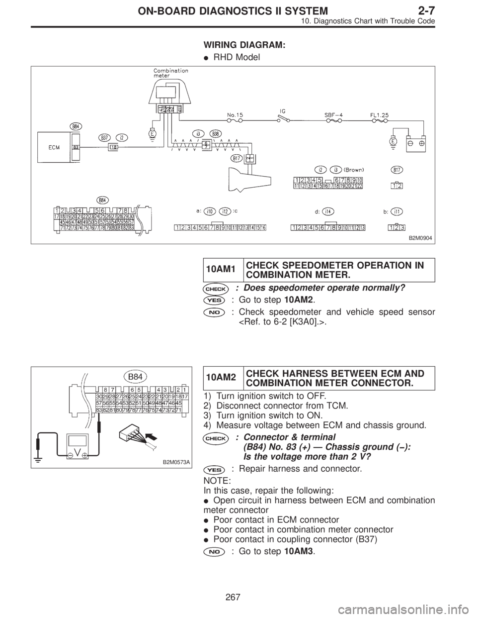
WIRING DIAGRAM:
�RHD Model
B2M0904
10AM1CHECK SPEEDOMETER OPERATION IN
COMBINATION METER.
: Does speedometer operate normally?
: Go to step10AM2.
: Check speedometer and vehicle speed sensor
.
B2M0573A
10AM2CHECK HARNESS BETWEEN ECM AND
COMBINATION METER CONNECTOR.
1) Turn ignition switch to OFF.
2) Disconnect connector from TCM.
3) Turn ignition switch to ON.
4) Measure voltage between ECM and chassis ground.
: Connector & terminal
(B84) No. 83 (+)—Chassis ground (�):
Is the voltage more than 2 V?
: Repair harness and connector.
NOTE:
In this case, repair the following:
�Open circuit in harness between ECM and combination
meter connector
�Poor contact in ECM connector
�Poor contact in combination meter connector
�Poor contact in coupling connector (B37)
: Go to step10AM3.
267
2-7ON-BOARD DIAGNOSTICS II SYSTEM
10. Diagnostics Chart with Trouble Code
Page 2036 of 2890
B2M0574A
10AM3CHECK HARNESS BETWEEN ECM AND
COMBINATION METER CONNECTOR.
1) Turn ignition switch to OFF.
2) Disconnect connector from ECM.
3) Measure resistance of harness between ECM connec-
tor and chassis ground.
: Connector & terminal
(B84) No. 83—Chassis ground:
Is the resistance less than 10Ω?
: Repair short circuit in harness between ECM and
combination meter connector.
: Repair poor contact in ECM connector.
268
2-7ON-BOARD DIAGNOSTICS II SYSTEM
10. Diagnostics Chart with Trouble Code
Page 2039 of 2890
 Turn ignition switch to ON.
2) Start engine, and idle it.
: Is there a fault in air intake system?
NOTE:
Check the following items.
�Loose installation of intake mani")
10AN1
CHECK AIR INTAKE SYSTEM.
1) Turn ignition switch to ON.
2) Start engine, and idle it.
: Is there a fault in air intake system?
NOTE:
Check the following items.
�Loose installation of intake manifold, idle air control sole-
noid valve and throttle body
�Cracks of intake manifold gasket, idle air control sole-
noid valve gasket and throttle body gasket
�Loose connections and cracks of idle air control solenoid
valve by-pass hoses
�Disconnections of vacuum hoses
: Repair or replace air intake system.
: Go to step10AN2.
B2M0576A
10AN2
CHECK OUTPUT SIGNAL FROM ECM.
1) Turn ignition switch to ON.
2) Measure voltage between ECM and chassis ground.
: Connector & terminal
(B84) No. 13 (+)—Chassis ground (�):
Is the voltage more than 3 V?
: Go to next.
: Go to step10AN4.
: Connector & terminal
(B84) No. 14 (+)—Chassis ground (�):
Is the voltage more than 3 V?
: Go to next step 3).
: Go to step10AN4.
271
2-7ON-BOARD DIAGNOSTICS II SYSTEM
10. Diagnostics Chart with Trouble Code
 Turn ignition switch to ON.
2) Measure voltage between vent control solenoid valve
and chassis ground.
: Connector & terminal
(R69")

1) Measure voltage between ECM connector and chassis
ground.
: Connector & terminal
(B84) No. 21 (+)—Chassi")
 Measure resistance of harness between fuel tank
pressure sensor connector and chassis ground.
: Connector & terminal
(R47) No. 1—Chassis ground:
Is the resistance more than 500 kΩ?
:")
 Turn ignition switch to OFF.
2) Disconnect connector from ECM.
3) Measure resistance of harness between ECM connec-
tor and")