Page 2116 of 2890
 Separate bulkhead wiring harness connector (B38)
and instrument panel wiring harness connector (i3).
15) Measure resistance of harness between bulkhead wir-
ing harness connector and chas")
B2M0944A
14) Separate bulkhead wiring harness connector (B38)
and instrument panel wiring harness connector (i3).
15) Measure resistance of harness between bulkhead wir-
ing harness connector and chassis ground.
: Connector & terminal
(B99) No. 20—Chassis ground:
Is the resistance less than 10Ω?
: Repair short circuit in bulkhead wiring harness.
: Repair short circuit in instrument panel wiring har-
ness.
G2M0340
10BP10CHECK HARNESS BETWEEN ECM, COM-
BINATION METER AND FUEL PUMP
CONNECTOR. (RHD MODEL)
1) Turn ignition switch to OFF.
2) Remove fuel pump access hole lid located on the right
rear of luggage compartment floor.
B2M0940A
3) Disconnect connector from fuel pump.
4) Measure resistance of harness between fuel pump con-
nector and chassis ground.
: Connector & terminal
(R58) No. 3—Chassis ground:
Is the resistance less than 10Ω?
: Go to next step 5).
: Go to step10BP11.
G2M0863
5) Remove service hole cover located on the left rear of
luggage compartment floor.
B2M0940A
6) Disconnect connector from fuel sub meter unit.
7) Measure resistance of harness between fuel pump con-
nector and chassis ground.
: Connector & terminal
(R58) No. 3—Chassis ground:
Is the resistance less than 10Ω?
: Repair short circuit in harness between fuel pump
and fuel sub meter unit connector.
: Go to next step 8).
348
2-7ON-BOARD DIAGNOSTICS II SYSTEM
10. Diagnostics Chart with Trouble Code
Page 2117 of 2890
 Separate fuel tank cord connector (R57) and rear wir-
ing harness connector (R15).
9) Measure resistance of harness between fuel sub meter
unit connector and chassis ground.
: Connector &")
B2M0941A
8) Separate fuel tank cord connector (R57) and rear wir-
ing harness connector (R15).
9) Measure resistance of harness between fuel sub meter
unit connector and chassis ground.
: Connector & terminal
(R59) No. 1—Chassis ground:
Is the resistance less than 10Ω?
: Repair short circuit in fuel tank cord.
: Go to next step 10).
B2M0942A
10) Separate rear wiring harness connector (R1) and bulk-
head wiring harness connector (B97).
11) Measure resistance of harness between rear wiring
harness connector and chassis ground.
: Connector & terminal
(R15) No. 3—Chassis ground:
Is the resistance less than 10Ω?
: Go to next step 12).
: Repair short circuit in rear wiring harness.
B2M1022A
12) Measure resistance of harness between bulkhead wir-
ing connector and chassis ground.
: Connector & terminal
(B97) No. J2—Chassis ground:
Is the resistance less than 10Ω?
: Go to next step 13).
: Repair short circuit in harness between S.M.J.
and ECM connector.
B2M1022A
13) Separate bulkhead wiring harness connector (B38)
and instrument panel wiring harness connector (i3).
14) Measure resistance of harness between bulkhead wir-
ing harness connector and chassis ground.
: Connector & terminal
(B97) No. J2—Chassis ground:
Is the resistance less than 10Ω?
: Repair short circuit in bulkhead wiring harness.
: Repair short circuit in instrument panel wiring har-
ness.
349
2-7ON-BOARD DIAGNOSTICS II SYSTEM
10. Diagnostics Chart with Trouble Code
Page 2118 of 2890
![SUBARU LEGACY 1996 Service Repair Manual B6M0121
10BP11CHECK HARNESS BETWEEN COMBINA-
TION METER AND FUEL PUMP CONNEC-
TOR.
1) Connect connector to fuel pump.
2) Pull out combination meter from instrument panel. <Ref.
to 6-2 [W13A1].>
3) Dis](/manual-img/17/57433/w960_57433-2117.png "SUBARU LEGACY 1996 Service Repair Manual B6M0121
10BP11CHECK HARNESS BETWEEN COMBINA-
TION METER AND FUEL PUMP CONNEC-
TOR.
1) Connect connector to fuel pump.
2) Pull out combination meter from instrument panel. <Ref.
to 6-2 [W13A1].>
3) Dis")
B6M0121
10BP11CHECK HARNESS BETWEEN COMBINA-
TION METER AND FUEL PUMP CONNEC-
TOR.
1) Connect connector to fuel pump.
2) Pull out combination meter from instrument panel.
to 6-2 [W13A1].>
3) Disconnect connector from combination meter.
B2M0945A
4) Measure resistance of harness between combination
meter connector and chassis ground.
: Connector & terminal
(i10) No. 3—Chassis ground:
Is the resistance less than 200Ω?
: Go to step10BP12.
: Repair harness and connector.
NOTE:
In this case, repair the following:
�Open circuit in harness between combination meter con-
nector and junction A on rear wiring harness
�Poor contact in coupling connectors (i3, and B99 (LHD)/
B97 (RHD))
10BP12
CHECK COMBINATION METER.
1) Disconnect speedometer cable from combination meter
and remove combination meter.
: Is the fuel meter installation screw tightened
securely?
: Go to next step 2).
: Tighten fuel meter installation screw securely.
2) Remove printed circuit plate assembly from combina-
tion meter assembly.
: Is there flaw or burning on printed circuit
plate assembly?
: Replace printed circuit plate assembly.
: Replace fuel meter assembly.
350
2-7ON-BOARD DIAGNOSTICS II SYSTEM
10. Diagnostics Chart with Trouble Code
Page 2121 of 2890
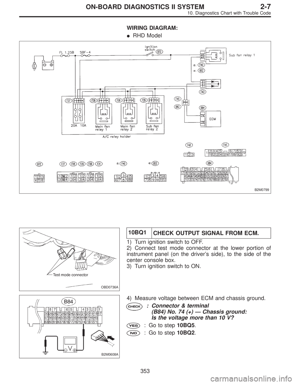
WIRING DIAGRAM:
�RHD Model
B2M0799
OBD0736A
10BQ1
CHECK OUTPUT SIGNAL FROM ECM.
1) Turn ignition switch to OFF.
2) Connect test mode connector at the lower portion of
instrument panel (on the driver’s side), to the side of the
center console box.
3) Turn ignition switch to ON.
B2M0608A
4) Measure voltage between ECM and chassis ground.
: Connector & terminal
(B84) No. 74 (+)—Chassis ground:
Is the voltage more than 10 V?
: Go to step10BQ5.
: Go to step10BQ2.
353
2-7ON-BOARD DIAGNOSTICS II SYSTEM
10. Diagnostics Chart with Trouble Code
Page 2125 of 2890
B2M0611A
10BQ5CHECK SHORT CIRCUIT IN RADIATOR
FAN RELAY 1 CONTROL CIRCUIT.
1) Turn ignition switch to OFF.
2) Remove main fan relay 1 and sub fan relay 1. (with A/C
models)
Remove main fan relay. (without A/C models)
3) Disconnect test mode connector.
4) Turn ignition switch to ON.
5) Measure voltage between ECM and chassis ground.
: Connector & terminal
(B84) No. 74 (+)—Chassis ground (�):
Is the voltage more than 10 V?
: Repair short circuit in radiator fan relay 1 control
circuit and replace ECM.
: Go to next.
: Is there poor contact in ECM connector?
: Repair poor contact in ECM connector.
: Replace ECM.
357
2-7ON-BOARD DIAGNOSTICS II SYSTEM
10. Diagnostics Chart with Trouble Code
Page 2131 of 2890
OBD0514A
10BT1CHECK HARNESS BETWEEN TCM AND
CCM CONNECTOR.
1) Turn ignition switch to OFF.
2) Disconnect connectors from TCM and CCM.
3) Measure resistance of harness between TCM and CCM
connector.
: Connector & terminal
(B56) No. 3—(B94) No. 3:
Is the resistance less than 1Ω?
: Go to next step 4).
: Repair open circuit in harness between TCM and
CCM connector.
OBD0515A
4) Measure resistance of harness between TCM and
chassis ground.
: Connector & terminal
(B56) No. 3—Chassis ground:
Is the resistance less than 10Ω?
: Repair short circuit in harness between TCM and
CCM connector.
: Go to step10BT2.
363
2-7ON-BOARD DIAGNOSTICS II SYSTEM
10. Diagnostics Chart with Trouble Code
Page 2132 of 2890
OBD0513A
10BT2
CHECK INPUT SIGNAL FOR TCM.
1) Connect connector to TCM and CCM.
2) Lift-up the vehicle or set the vehicle on free rollers.
CAUTION:
On AWD models, raise all wheels off ground.
3) Start the engine.
4) Cruise control main switch to ON.
5) TCS OFF switch to ON. (with TCS models only)
6) Move selector lever to“D”and slowly increase vehicle
speed to 50 km/h (31 MPH).
7) Cruise control set switch to ON.
8) Measure voltage between TCM and chassis ground.
: Connector & terminal
(B56) No. 3 (+)—Chassis ground (�):
Is the voltage less than 1 V?
: Go to next.
: Check cruise control set circuit.
[T7A0].>
: Is there poor contact in TCM connector?
: Repair poor contact in TCM connector.
: Replace TCM.
364
2-7ON-BOARD DIAGNOSTICS II SYSTEM
10. Diagnostics Chart with Trouble Code
Page 2134 of 2890
10BU1
CHECK TRANSMISSION TYPE.
: Is transmission type AT?
: Go to step10BU2.
: Check AT/MT identification circuit.
[T10BW0].>
B2M0615A
10BU2CHECK HARNESS BETWEEN ECM AND
TCM CONNECTOR.
1) Turn ignition switch to ON.
2) Measure voltage between ECM and chassis ground.
: Connector & terminal
(B84) No. 80 (+)—Chassis ground (�):
Is the voltage more than 4 V?
: Repair harness and connector.
NOTE:
In this case, repair the following:
�Open circuit in harness between ECM and TCM connec-
tor
�Poor contact in ECM connector
�Poor contact in TCM connector
: Go to next.
: Connector & terminal
(B84) No. 80 (+)—Chassis ground (�):
Is the voltage less than 1 V?
: Go to step10BU3.
: Although MIL illuminates, circuit is now normal.
NOTE:
In this case, repair the following:
�Poor contact in ECM connector
�Poor contact in TCM connector
366
2-7ON-BOARD DIAGNOSTICS II SYSTEM
10. Diagnostics Chart with Trouble Code
 Turn ignition switch to OFF.
2) Remove main fan relay 1 and sub fan relay 1. (with A/C
models)
Remove main fan relay. (wit")
 Turn ignition switch to OFF.
2) Disconnect connectors from TCM and CCM.
3) Measure resistance of harness between TCM and CCM
connector.
:")
 Connect connector to TCM and CCM.
2) Lift-up the vehicle or set the vehicle on free rollers.
CAUTION:
On AWD models, raise all wheels off ground.
3) Start")
![SUBARU LEGACY 1996 Service Repair Manual 10BU1
CHECK TRANSMISSION TYPE.
: Is transmission type AT?
: Go to step10BU2.
: Check AT/MT identification circuit. <Ref. to 2-7
[T10BW0].>
B2M0615A
10BU2CHECK HARNESS BETWEEN ECM AND
TCM CONNECTOR.
1)](/manual-img/17/57433/w960_57433-2133.png "SUBARU LEGACY 1996 Service Repair Manual 10BU1
CHECK TRANSMISSION TYPE.
: Is transmission type AT?
: Go to step10BU2.
: Check AT/MT identification circuit. <Ref. to 2-7
[T10BW0].>
B2M0615A
10BU2CHECK HARNESS BETWEEN ECM AND
TCM CONNECTOR.
1)")