Page 1203 of 2890
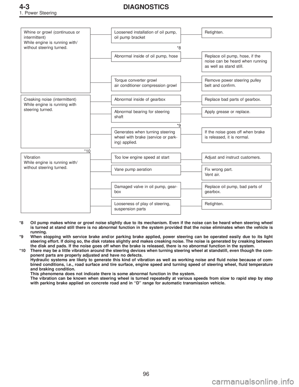
Whine or growl (continuous or
intermittent)
While engine is running with/
without steering turned.Loosened installation of oil pump,
oil pump bracketRetighten.
*8
Abnormal inside of oil pump, hoseReplace oil pump, hose, if the
noise can be heard when running
as well as stand still.
Torque converter growl
air conditioner compression growlRemove power steering pulley
belt and confirm.
Creaking noise (intermittent)
While engine is running with
steering turned.Abnormal inside of gearboxReplace bad parts of gearbox.
Abnormal bearing for steering
shaftApply grease or replace.
*9
Generates when turning steering
wheel with brake (service or park-
ing) applied.If the noise goes off when brake
is released, it is normal.
*10
Vibration
While engine is running with/
without steering turned.
Too low engine speed at startAdjust and instruct customers.
Vane pump aerationFix wrong part.
Vent air.
Damaged valve in oil pump, gear-
boxReplace oil pump, bad parts of
gearbox.
Looseness of play of steering,
suspension partsRetighten.
*8 Oil pump makes whine or growl noise slightly due to its mechanism. Even if the noise can be heard when steering wheel
is turned at stand still there is no abnormal function in the system provided that the noise eliminates when the vehicle is
running.
*9 When stopping with service brake and/or parking brake applied, power steering can be operated easily due to its light
steering effort. If doing so, the disk rotates slightly and makes creaking noise. The noise is generated by creaking between
the disk and pads. If the noise goes off when the brake is released, there is no abnormal function in the system.
*10 There may be a little vibration around the steering devices when turning steering wheel at standstill, even though the com-
ponent parts are properly adjusted and have no defects.
Hydraulic systems are likely to generate this kind of vibration as well as working noise and fluid noise because of com-
bined conditions, i.e., road surface and tire surface, engine speed and turning speed of steering wheel, fluid temperature
and braking condition.
This phenomena does not indicate there is some abnormal function in the system.
The vibration can be known when steering wheel is turned repeatedly at various speeds from slow to rapid step by step
with parking brake applied on concrete road and in“D”range for automatic transmission vehicle.
96
4-3DIAGNOSTICS
1. Power Steering
Page 1270 of 2890
Air bleeder tightening torque:
8±1 N⋅m (0.8±0.1 kg-m, 5.8±0.7 ft-lb)
5) Perform these steps for the brakes connecting to the
secondary chamber of master cylinder, first, and then for
the ones connecting to primary chamber. With all proce-
dures completed, fully depress the brake pedal and keep
it in that position for approximately 20 seconds to make
sure that there is no leak evident in the entire system.
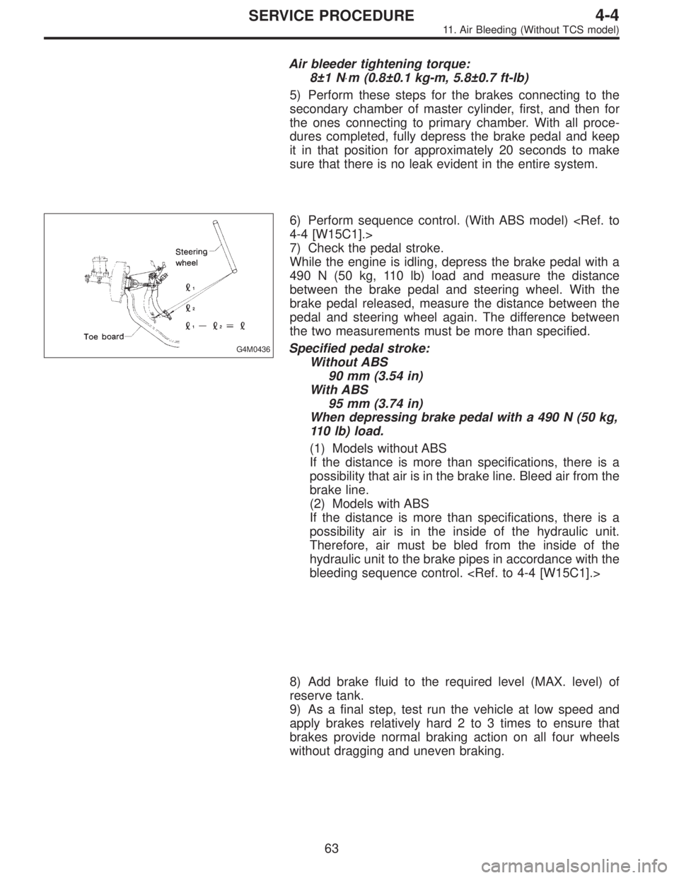
G4M0436
6) Perform sequence control. (With ABS model)
4-4 [W15C1].>
7) Check the pedal stroke.
While the engine is idling, depress the brake pedal with a
490 N (50 kg, 110 lb) load and measure the distance
between the brake pedal and steering wheel. With the
brake pedal released, measure the distance between the
pedal and steering wheel again. The difference between
the two measurements must be more than specified.
Specified pedal stroke:
Without ABS
90 mm (3.54 in)
With ABS
95 mm (3.74 in)
When depressing brake pedal with a 490 N (50 kg,
110 lb) load.
(1) Models without ABS
If the distance is more than specifications, there is a
possibility that air is in the brake line. Bleed air from the
brake line.
(2) Models with ABS
If the distance is more than specifications, there is a
possibility air is in the inside of the hydraulic unit.
Therefore, air must be bled from the inside of the
hydraulic unit to the brake pipes in accordance with the
bleeding sequence control.
8) Add brake fluid to the required level (MAX. level) of
reserve tank.
9) As a final step, test run the vehicle at low speed and
apply brakes relatively hard 2 to 3 times to ensure that
brakes provide normal braking action on all four wheels
without dragging and uneven braking.
63
4-4SERVICE PROCEDURE
11. Air Bleeding (Without TCS model)
Page 1298 of 2890
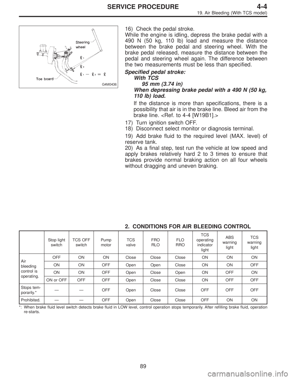
G4M0436
16) Check the pedal stroke.
While the engine is idling, depress the brake pedal with a
490 N (50 kg, 110 lb) load and measure the distance
between the brake pedal and steering wheel. With the
brake pedal released, measure the distance between the
pedal and steering wheel again. The difference between
the two measurements must be less than specified.
Specified pedal stroke:
With TCS
95 mm (3.74 in)
When depressing brake pedal with a 490 N (50 kg,
110 lb) load.
If the distance is more than specifications, there is a
possibility that air is in the brake line. Bleed air from the
brake line.
17) Turn ignition switch OFF.
18) Disconnect select monitor or diagnosis terminal.
19) Add brake fluid to the required level (MAX. level) of
reserve tank.
20) As a final step, test run the vehicle at low speed and
apply brakes relatively hard 2 to 3 times to ensure that
brakes provide normal braking action on all four wheels
without dragging and uneven braking.
2. CONDITIONS FOR AIR BLEEDING CONTROL
Stop light
switchTCS OFF
switchPump
motorTCS
valveFRO
RLOFLO
RROTCS
operating
indicator
lightABS
warning
lightTCS
warning
light
Air
bleeding
control is
operating.OFF ON ON Close Close Close ON ON ON
ON ON OFF Open Open Close ON ON OFF
ON ON OFF Open Close Open ON OFF ON
ON or OFF OFF OFF Open Close Close ON OFF OFF
Stops tem-
porarily.*——OFF Open Close Close OFF OFF OFF
Prohibited.——OFF Open Close Close OFF ON ON
*: When brake fluid level switch detects brake fluid in LOW level, control operation stops temporarily. After refilling brake fluid, operation
re-starts.
89
4-4SERVICE PROCEDURE
19. Air Bleeding (With TCS model)
Page 1577 of 2890
6. COMBINATION SWITCH
Inspection standard:
�A vehicle damaged in a collision (regardless of whether
or not airbag is deployed).
�The designated trouble code is output during self-diag-
nosis. (Refer to“Diagnostics”Section.)
Replacement standard:
�Combination switch or steering roll connector is
deformed or cracked.
B5M0095
7. STEERING WHEEL
Inspection standard:
�A vehicle damaged in a collision (regardless of whether
or not airbag is deployed).
Replacement standard:
�Check steering wheel insert for cracks or deformities.
�Check to ensure that new airbag module is properly
installed in steering wheel.
�After installing airbag module, check to ensure that it is
free of interference with steering wheel and that clearance
between the two is equal at all points.
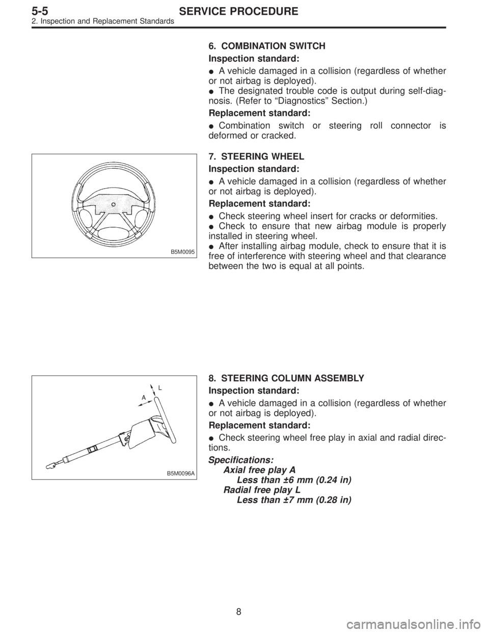
B5M0096A
8. STEERING COLUMN ASSEMBLY
Inspection standard:
�A vehicle damaged in a collision (regardless of whether
or not airbag is deployed).
Replacement standard:
�Check steering wheel free play in axial and radial direc-
tions.
Specifications:
Axial free play A
Less than ±6 mm (0.24 in)
Radial free play L
Less than ±7 mm (0.28 in)
8
5-5SERVICE PROCEDURE
2. Inspection and Replacement Standards
Page 1584 of 2890
G5M0312
3) Remove lower cover.
Disconnect airbag connector (AB3) and (AB8) below steer-
ing column.
CAUTION:
Do not reconnect airbag connector at steering column
until front sensors are securely re-installed.
G5M0313
4) Remove console box. Discon-
nect 2-pin blue connector (AB4) (right side front sensor)
and 2-pin orange connector (AB5) (left side front sensor)
from airbag control module.
G5M0314
5) Roll up floor mat and side sill cover.
[W5A10].> Remove front sensor harness from clip and pro-
tector.
6) Remove front wheels.
7) Remove front mud guard.
G5M0315
8) Remove wiring harness clips.
G5M0316
9) Remove grommet.
14
5-5SERVICE PROCEDURE
4. Front Sensor
Page 1590 of 2890
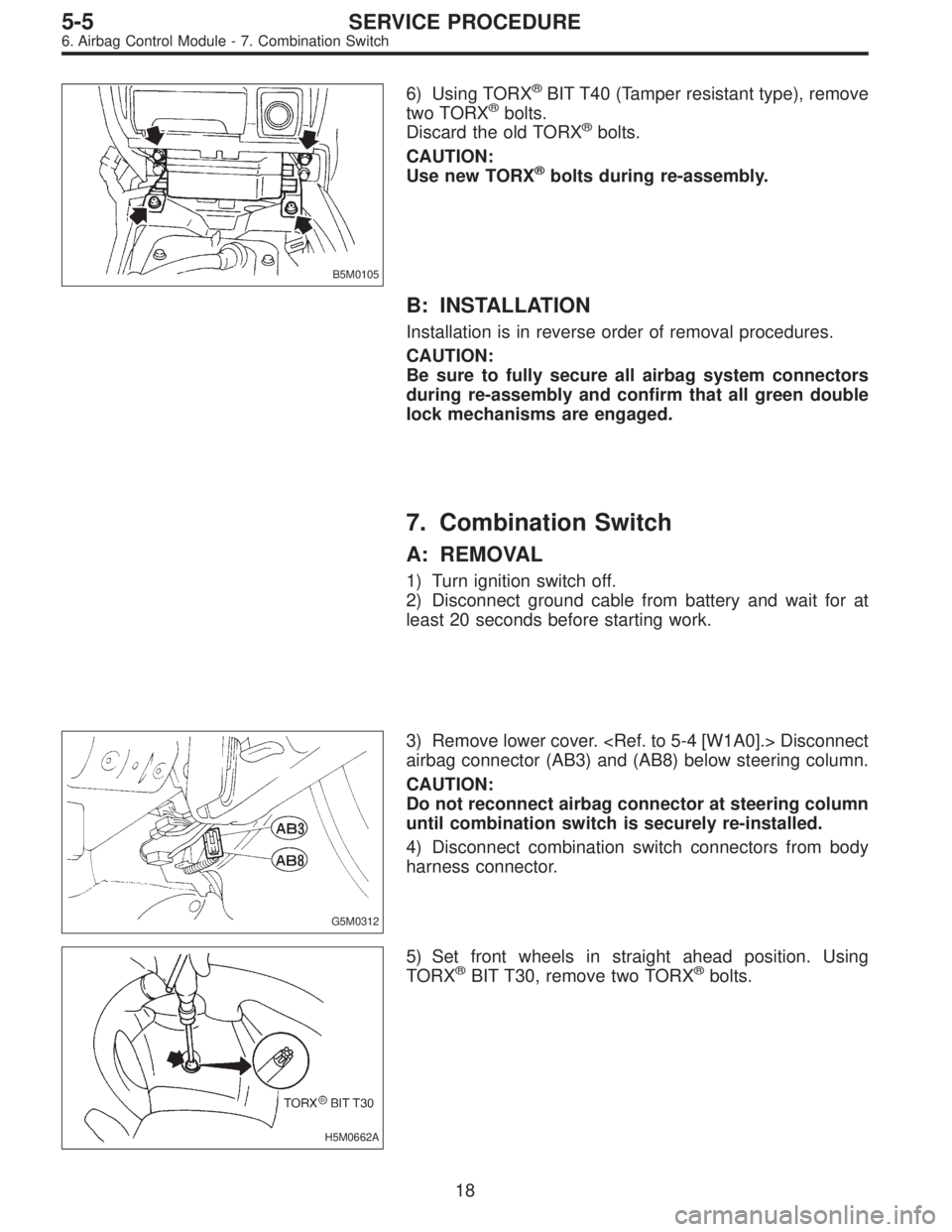
B5M0105
6) Using TORX®BIT T40 (Tamper resistant type), remove
two TORX®bolts.
Discard the old TORX®bolts.
CAUTION:
Use new TORX
®bolts during re-assembly.
B: INSTALLATION
Installation is in reverse order of removal procedures.
CAUTION:
Be sure to fully secure all airbag system connectors
during re-assembly and confirm that all green double
lock mechanisms are engaged.
7. Combination Switch
A: REMOVAL
1) Turn ignition switch off.
2) Disconnect ground cable from battery and wait for at
least 20 seconds before starting work.
G5M0312
3) Remove lower cover. Disconnect
airbag connector (AB3) and (AB8) below steering column.
CAUTION:
Do not reconnect airbag connector at steering column
until combination switch is securely re-installed.
4) Disconnect combination switch connectors from body
harness connector.
H5M0662A
5) Set front wheels in straight ahead position. Using
TORX®BIT T30, remove two TORX®bolts.
18
5-5SERVICE PROCEDURE
6. Airbag Control Module - 7. Combination Switch
Page 1591 of 2890
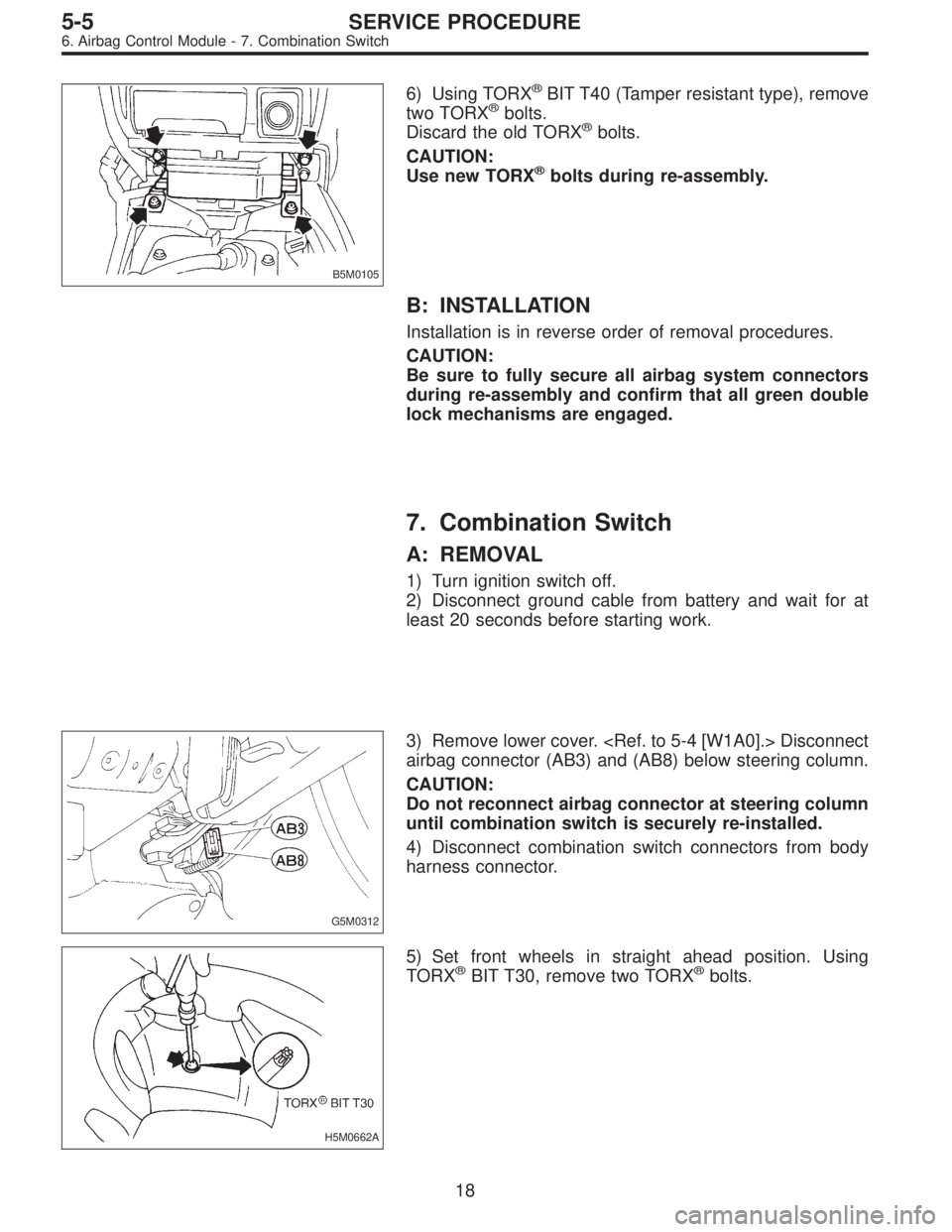
B5M0105
6) Using TORX®BIT T40 (Tamper resistant type), remove
two TORX®bolts.
Discard the old TORX®bolts.
CAUTION:
Use new TORX
®bolts during re-assembly.
B: INSTALLATION
Installation is in reverse order of removal procedures.
CAUTION:
Be sure to fully secure all airbag system connectors
during re-assembly and confirm that all green double
lock mechanisms are engaged.
7. Combination Switch
A: REMOVAL
1) Turn ignition switch off.
2) Disconnect ground cable from battery and wait for at
least 20 seconds before starting work.
G5M0312
3) Remove lower cover. Disconnect
airbag connector (AB3) and (AB8) below steering column.
CAUTION:
Do not reconnect airbag connector at steering column
until combination switch is securely re-installed.
4) Disconnect combination switch connectors from body
harness connector.
H5M0662A
5) Set front wheels in straight ahead position. Using
TORX®BIT T30, remove two TORX®bolts.
18
5-5SERVICE PROCEDURE
6. Airbag Control Module - 7. Combination Switch
Page 1592 of 2890
H5M0664
6) Disconnect airbag connector on back of airbag module.
Remove airbag module, and place it
with pad side facing upward.
G5M0332
7) Using steering puller, remove steering wheel.
CAUTION:
Do not allow connector to interfere when removing
steering wheel.
B5M0106
8) Remove steering column covers.
9) Removing two retaining screws, remove combination
switch.
B: ADJUSTMENT
1. CENTERING ROLL CONNECTOR
Before installing steering wheel, make sure to center roll
connector built into combination switch.
1) Make sure that front wheels are positioned straight
ahead.
2) Install steering gearbox, steering shaft and combination
switch properly. Turn roll connector pin�
1clockwise until
it stops.
H5M0663A
3) Then, back off roll connector pin�1approximately 2.65
turns until“�”marks aligned.
19
5-5SERVICE PROCEDURE
7. Combination Switch