Page 1008 of 2890
1. On-car Services
A: WHEEL ALIGNMENT
Check, adjust and/or measure wheel alignment in accor-
dance with procedures indicated below:
1. Wheel arch height (Front and rear)
2. Camber (Front and rear)
3. Caster (Front)
4. Front toe-in
5. Rear toe-in
6. Thrust angle (Rear)
7. Wheel steering angle
�
�
�
�
�
�
7
4-1SERVICE PROCEDURE
1. On-car Services
Page 1009 of 2890
1. WHEEL ARCH HEIGHT
1) Adjust tire pressure to specifications.
2) Set vehicle under“curb weight”conditions. (Empty lug-
gage compartment, install spare tire, jack, service tools,
and top up fuel tank.)
3) Set steering wheel in a wheel-forward position.
4) Suspend thread from wheel arch (point“A”in figure
below) to determine a point directly above center of
spindle.
5) Measure distance between measuring point and center
of spindle.
B4M0566A
VehiclesSpecified wheel arch height mm (in)
Front Rear
SedanFWD 385
+12
�24(15.16+0.47
�0.94) 369+12
�24(14.53+0.47
�0.94)
AWD 385
+12
�24(15.16+0.47
�0.94) 369+12
�24(14.53+0.47
�0.94)
WagonFWD 385
+12
�24(15.16+0.47
�0.94) 379+12
�24(14.92+0.47
�0.94)
AWD 385
+12
�24(15.16+0.47
�0.94) 379+12
�24(14.92+0.47
�0.94)
OUTBACK AWD 420
+12
�24(16.54+0.47
�0.94) 419+12
�24(16.50+0.47
�0.94)
8
4-1SERVICE PROCEDURE
1. On-car Services
Page 1012 of 2890
 Loosen the left and right side steering tie-rods lock nuts.
2) Turn the left and right tie rods equal amounts until the
toe-in is at the specification.
Both the left and right t")
G4M0482
�Adjustment
1) Loosen the left and right side steering tie-rods lock nuts.
2) Turn the left and right tie rods equal amounts until the
toe-in is at the specification.
Both the left and right tie-rods are right-hand threaded. To
increase toe-in, turn both tie-rods clockwise equal amounts
(as viewed from the inside of the vehicle).
3) Tighten tie-rod lock nut.
Tightening torque:
83±5 N⋅m (8.5±0.5 kg-m, 61.5±3.6 ft-lb)
CAUTION:
Correct tie-rod boot, if it is twisted.
NOTE:
Check the left and right wheel steering angle is within
specifications.
M4A0059
4. REAR WHEEL TOE-IN (FWD MODEL)
�Inspection
1) Using a toe-in gauge, measure rear wheel toe-in.
Toe-in: 0±3 mm (0±0.12 in)
2) Mark rear sides of left and right tires at height corre-
sponding to center of spindles and measure distance“B”
between marks.
3) Move vehicle forward so that marks line up with front
sides at height corresponding to center of spindles.
4) Measure distance“A”between left and right marks.
Toe-in can then be obtained by the following equation:
B�A = Toe-in
G4M0483
�Adjustment
1) Remove cap from lateral link and loosen self-locking
nut.
CAUTION:
�When loosening or tightening adjusting bolt, hold
the bolt head and loosen self-locking nut.
�Replace self-locking nut with a new one.
2) Using two wrenches, turn adjusting wheel and adjusting
bolt equally in opposite directions so that toe-in is at the
specification.
11
4-1SERVICE PROCEDURE
1. On-car Services
Page 1016 of 2890
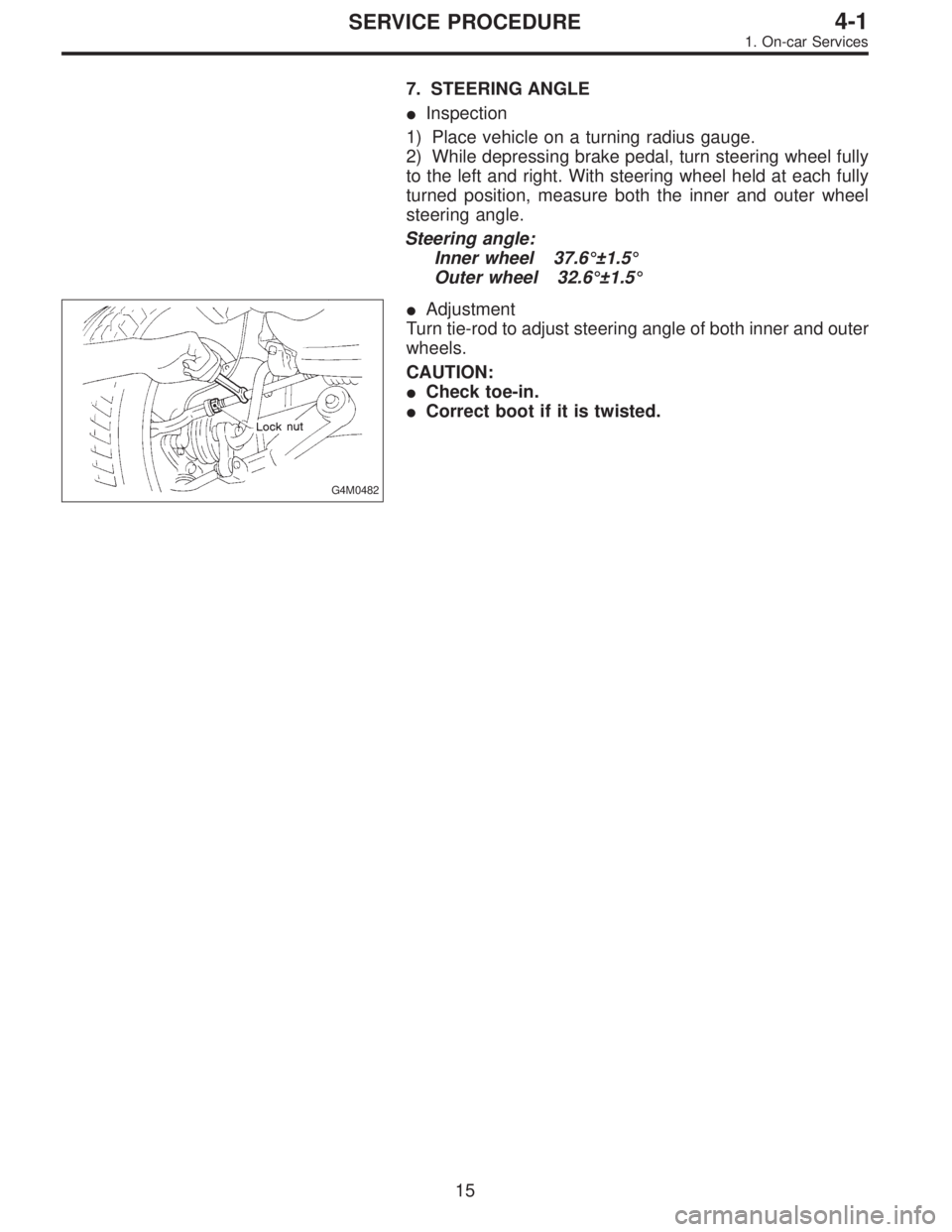
7. STEERING ANGLE
�Inspection
1) Place vehicle on a turning radius gauge.
2) While depressing brake pedal, turn steering wheel fully
to the left and right. With steering wheel held at each fully
turned position, measure both the inner and outer wheel
steering angle.
Steering angle:
Inner wheel 37.6°±1.5°
Outer wheel 32.6°±1.5°
G4M0482
�Adjustment
Turn tie-rod to adjust steering angle of both inner and outer
wheels.
CAUTION:
�Check toe-in.
�Correct boot if it is twisted.
15
4-1SERVICE PROCEDURE
1. On-car Services
Page 1029 of 2890
 Disconnect ground cable from battery.
2) Loosen front wheel nuts.
3) Lift-up vehicle, and remove front tires and wheels.
4) Remove both stabilizer and jack-u")
G4M0520
6. Front Crossmember
A: REMOVAL
1) Disconnect ground cable from battery.
2) Loosen front wheel nuts.
3) Lift-up vehicle, and remove front tires and wheels.
4) Remove both stabilizer and jack-up plate.
5) Disconnect tie-rod end from housing.
6) Remove front exhaust pipe.
G4M0521
7) Remove front transverse link from front crossmember
and body.
8) Remove nuts attaching engine mount cushion rubber to
crossmember.
9) Remove self-locking nuts connecting steering U/J and
pinion shaft.
10) Lift engine by approx. 10 mm (0.39 in) by using chain
block.
11) Support crossmember with a jack, remove nuts secur-
ing crossmember to body and lower crossmember gradu-
ally along with steering gearbox.
CAUTION:
When removing crossmember downward, be careful
that tie-rod end does not interfere with DOJ boot.
B: INSTALLATION
1) Installation is in the reverse order of removal proce-
dures.
CAUTION:
Always tighten rubber bushing when wheels are in full
contact with the ground and vehicle is at curb weight
condition.
Tightening torque:
Transverse link bushing to crossmember:
98±15 N⋅m (10.0±1.5 kg-m, 72±11 ft-lb)
Stabilizer to bushing:
25±4 N⋅m (2.5±0.4 kg-m, 18.1±2.9 ft-lb)
Tie-rod end to housing:
27.0±2.5 N⋅m (2.75±0.25 kg-m, 19.9±1.8 ft-lb)
Front cushion rubber to crossmember:
69±15 N⋅m (7.0±1.5 kg-m, 51±11 ft-lb)
Universal joint to pinion shaft:
24±3 N⋅m (2.4±0.3 kg-m, 17.4±2.2 ft-lb)
Crossmember to body:
98±15 N⋅m (10.0±1.5 kg-m, 72±11 ft-lb)
2) Purge air from power steering system.
NOTE:
Check wheel alignment and adjust if necessary.
28
4-1SERVICE PROCEDURE
6. Front Crossmember
Page 1108 of 2890
 5.3 (17.4) 5.6 (18.4)
Steering angle (Inside-Outside) 37.6°—32.6°34.4°—30.2°
S")
1. Steering System
A: SPECIFICATIONS
Except OUTBACK model OUTBACK model
Whole systemMinimum turning radius m (ft) 5.3 (17.4) 5.6 (18.4)
Steering angle (Inside-Outside) 37.6°—32.6°34.4°—30.2°
Steering wheel diameter mm (in) 385 (15.16)
Overall gear ratio (Turns, lock to lock) 16.5 (3.2) 19 (3.4)
GearboxType Rack and pinion, Integral
Backlash 0 (Automatically adjustable)
Valve (Power steering system) Rotary valve
Pump
(Power steering system)Type Vane pump
Oil tank Installed on pump
Output cm
3(cu in)/rev. 7.2 (0.439)
Relief pressure kPa (kg/cm
2, psi) 7,355 (75, 1,067)
Hydraulic fluid controlDropping in response to increased engine
revolutions
Hydraulic fluid�(US qt, Imp qt)1,000 rpm: 7 (7.4, 6.2)
3,000 rpm: 5 (5.3, 4.4)
Range of revolution rpm 500—7,500
Revolving direction Clockwise
Working fluid
(Power steering system)Name ATF DEXRON II, IIE or III
Capacity Oil tank�(US qt, Imp qt)
Total0.35 (0.4, 0.3)
0.7 (0.7, 0.6)
2
4-3SPECIFICATIONS AND SERVICE DATA
1. Steering System
Page 1109 of 2890
 17 (0.67)
Turning angleInner tire & wheel 37.6°34.4°
Outer tire & wheel 32.6°30.2°
Steering shaftClearance betwe")
B: SERVICE DATA
Except OUTBACK model OUTBACK model
Steering wheel Free play mm (in) 17 (0.67)
Turning angleInner tire & wheel 37.6°34.4°
Outer tire & wheel 32.6°30.2°
Steering shaftClearance between steering
wheel and column cover
mm (in)3.0 (0.118)
Steering gearbox
(Power steering system)Sliding resistance N (kg, lb) 240.3 (24.5, 54.0) or less
Rack shaft play in radial direc-
tion
mm (in)0.15 (0.0059) or less
Right-turn steering Horizontal movement: 0.3 (0.012) or less
Left-turn steering Vertical movement: 0.15 (0.0059) or less
Input shaft play mm (in)
In radial direction 0.18 (0.0071) or less
In axial direction 0.1 (0.004) or less
Turning resistance N (kg, lb)Within 30 mm (1.18 in) from rack center in straight ahead posi-
tion: Less than 11.18 (1.14, 2.51)
Maximum allowable value: 12.7 (1.3, 2.9)
Oil pump
(Power steering system)Pulley shaft mm (in)
Radial play 0.4 (0.016) or less
Axial play 0.9 (0.035) or less
Pulley
Ditch deflection mm (in)
Resistance to rotation
N (kg, lb)1.0 (0.039) or less
9.22 (0.94, 2.07) or less
Regular pressure
kPa (kg/cm
2, psi)981 (10, 142) or less
Relief pressure
kPa (kg/cm
2, psi)7,355 (75, 1,067)
Steering wheel effort
(Power steering system)At standstill with engine
idling on a concrete road
N (kg, lb)31.4 (3.2, 7.1) or less
At standstill with engine
stalled on a concrete road
N (kg, lb)147 (15, 33) or less
C: RECOMMENDED POWER STEERING
FLUID
Recommended power steering fluid Manufacturer
ATF DEXRON II, ATF DEXRON IIE or ATF
DEXRON IIIB.P.
CALTEX
CASTROL
MOBIL
SHELL
TEXACO
3
4-3SPECIFICATIONS AND SERVICE DATA
1. Steering System
Page 1110 of 2890
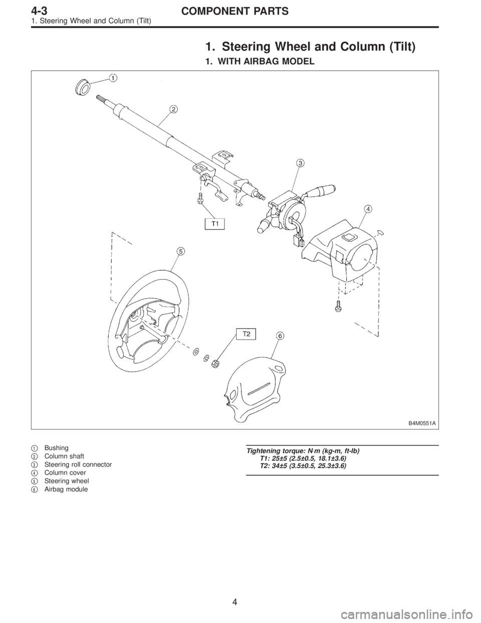
1. Steering Wheel and Column (Tilt)
1. WITH AIRBAG MODEL
B4M0551A
�1Bushing
�
2Column shaft
�
3Steering roll connector
�
4Column cover
�
5Steering wheel
�
6Airbag module
Tightening torque: N⋅m (kg-m, ft-lb)
T1: 25±5 (2.5±0.5, 18.1±3.6)
T2: 34±5 (3.5±0.5, 25.3±3.6)
4
4-3COMPONENT PARTS
1. Steering Wheel and Column (Tilt)

2. Camber (Front and rear)
3.")
 Adjust tire pressure to specifications.
2) Set vehicle under“curb weight”conditions. (Empty lug-
gage compartment, install spare tire, jack, service tools,
and top up fuel")