Page 1116 of 2890
1. Supplemental Restraint System
“Airbag”
Airbag system wiring harness is routed near the steering
wheel, steering shaft and column.
WARNING:
�All Airbag system wiring harness and connectors
are colored yellow. Do not use electrical test equip-
ment on these circuit.
�Be careful not to damage Airbag system wiring har-
ness when servicing the steering wheel, steering shaft
and column.
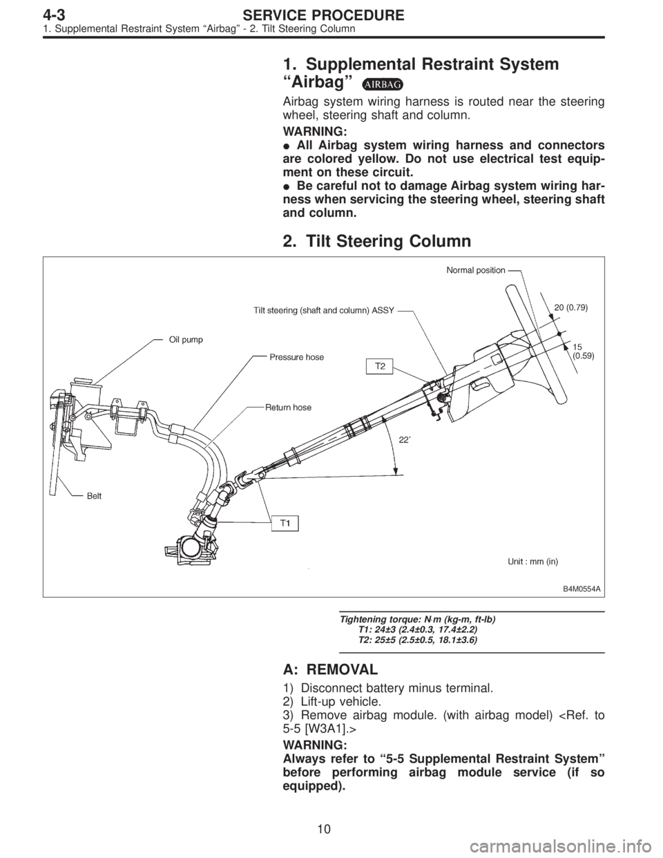
2. Tilt Steering Column
B4M0554A
Tightening torque: N⋅m (kg-m, ft-lb)
T1: 24±3 (2.4±0.3, 17.4±2.2)
T2: 25±5 (2.5±0.5, 18.1±3.6)
A: REMOVAL
1) Disconnect battery minus terminal.
2) Lift-up vehicle.
3) Remove airbag module. (with airbag model)
5-5 [W3A1].>
WARNING:
Always refer to“5-5 Supplemental Restraint System”
before performing airbag module service (if so
equipped).
10
4-3SERVICE PROCEDURE
1. Supplemental Restraint System“Airbag”- 2. Tilt Steering Column
Page 1117 of 2890
1. Supplemental Restraint System
“Airbag”
Airbag system wiring harness is routed near the steering
wheel, steering shaft and column.
WARNING:
�All Airbag system wiring harness and connectors
are colored yellow. Do not use electrical test equip-
ment on these circuit.
�Be careful not to damage Airbag system wiring har-
ness when servicing the steering wheel, steering shaft
and column.
2. Tilt Steering Column
B4M0554A
Tightening torque: N⋅m (kg-m, ft-lb)
T1: 24±3 (2.4±0.3, 17.4±2.2)
T2: 25±5 (2.5±0.5, 18.1±3.6)
A: REMOVAL
1) Disconnect battery minus terminal.
2) Lift-up vehicle.
3) Remove airbag module. (with airbag model)
5-5 [W3A1].>
WARNING:
Always refer to“5-5 Supplemental Restraint System”
before performing airbag module service (if so
equipped).
10
4-3SERVICE PROCEDURE
1. Supplemental Restraint System“Airbag”- 2. Tilt Steering Column
Page 1118 of 2890
 Remove steering wheel nut, then draw out steering
wheel from shaft using steering puller.
G4M0086
5) Remove universal joint bolts and then remove universal
joint.
CAUTION:
Scribe alignment")
G5M0332
4) Remove steering wheel nut, then draw out steering
wheel from shaft using steering puller.
G4M0086
5) Remove universal joint bolts and then remove universal
joint.
CAUTION:
Scribe alignment marks on universal joint so that it can
be reassembled at the original serration.
6) Remove trim panel under instrument panel.
7) Disconnect connectors for ignition switch and combina-
tion switch wiring harness under instrument panel.
B4M0127A
8) Remove the two bolts under instrument panel securing
steering shaft.
9) Pull out steering shaft assembly from hole on toe board.
CAUTION:
Be sure to remove universal joint before removing
steering shaft assembly installing bolts when remov-
ing steering shaft assembly or when lowering it for
servicing of other parts.
B4M0555
B: DISASSEMBLY
Remove the four screws securing upper and lower steer-
ing column covers, and the two screws securing combina-
tion switch, then remove related parts.
NOTE:
Steering column assembly can not to be disassembled.
11
4-3SERVICE PROCEDURE
2. Tilt Steering Column
Page 1120 of 2890
 Insert combination switch to upper column shaft, and
install lower column cover with tilt lever held in the lowered
position. Then route ignition key harness and combination
swi")
B4M0555
D: ASSEMBLY
1) Insert combination switch to upper column shaft, and
install lower column cover with tilt lever held in the lowered
position. Then route ignition key harness and combination
switch harness between column cover mounting bosses.
2) Fit upper column cover to lower column cover, and
tighten combination switch and column cover.
Tightening torque:
1.2±0.2 N⋅m (0.12±0.02 kg-m, 0.9±0.1 ft-lb)
CAUTION:
Don’t overtorque screw.
E: INSTALLATION
1) Insert end of steering shaft into toe board grommet.
2) Tighten steering shaft mounting bolts under instrument
panel.
Tightening torque:
25±5 N⋅m (2.5±0.5 kg-m, 18.1±3.6 ft-lb)
3) Connect ignition and combination switch connectors
under instrument panel.
4) Connect airbag system connector at harness spool.
NOTE:
Make sure to apply double lock.
5) Install universal joint.
(1) Align bolt hole on the long yoke side of universal
joint with the cutout at the serrated section of shaft end,
and insert universal joint.
(2) Align bolt hole on the short yoke side of universal
joint with the cutout at the serrated section of gearbox
assembly. Lower universal joint completely.
(3) Temporarily tighten bolt on the short yoke side.
Raise universal joint to make sure the bolt is properly
passing through the cutout at the serrated section.
(4) Tighten bolt on the long yoke side, then that on the
short yoke side.
Tightening torque:
24±3 N⋅m (2.4±0.3 kg-m, 17.4±2.2 ft-lb)
CAUTION:
�Make sure that universal joint bolts is tightened
through notch in shaft serration.
�Excessively large tightening torque of universal
joint bolts may lead to heavy steering wheel operation.
Standard clearance between gearbox to DOJ:
Over 15 mm (0.59 in)
13
4-3SERVICE PROCEDURE
2. Tilt Steering Column
Page 1121 of 2890
G5M0328
6) Align center of roll connector. (with airbag model)
CAUTION:
Ensure that front wheels are set in straight-forward
direction.
7) Set steering wheel to neutral and install it onto steering
shaft.
Tightening torque:
34±5 N⋅m (3.5±0.5 kg-m, 25.3±3.6 ft-lb)
Column cover-to-steering wheel clearance:
2 — 4 mm (0.08 — 0.16 in)
CAUTION:
Insert roll connector guide pin into guide hole on lower
end of surface of steering wheel to prevent damage.
Draw out airbag system connector, horn connector
and cruise control connectors from guide hole of
steering wheel lower end. (with airbag model)
8) Install airbag module to steering wheel. (with airbag
model)
WARNING:
Always refer to 5-5 [W3B1] before performing the ser-
vice operation.
14
4-3SERVICE PROCEDURE
2. Tilt Steering Column
Page 1123 of 2890
A: REMOVAL
1) Disconnect battery minus terminal.
2) Loosen front wheel nut.
3) Lift vehicle and remove front wheels.
4) Remove front exhaust pipe assembly.
WARNING:
Be careful, exhaust pipe is hot.
G4M0097
5) Using a puller, remove tie-rod end from knuckle arm
after pulling off cotter pin and removing castle nut.
G4M0098
6) Remove jack-up plate and front stabilizer.
G4M0099
7) Remove one pipe joint at the center of gearbox, and
connect vinyl hose to pipe and joint. Discharge fluid by
turning steering wheel fully clockwise and counterclock-
wise. Discharge fluid similarly from the other pipe.
G4M0086
8) Remove lower side bolt of universal joint, then remove
upper side bolt and lift the joint upward.
NOTE:
Place a mark on the joint and mating serration so that they
can be re-installed at the original position.
16
4-3SERVICE PROCEDURE
3. Steering Gearbox (Power Steering System) [LHD model]
Page 1131 of 2890
![SUBARU LEGACY 1996 Service Repair Manual �Make adjustment so that steering wheel can be rotated
fully from lock to lock without binding.
9) Check for service limit as per article of“Service limit”.
<Ref. to 4-3 [W3C1].> Make replacement](/manual-img/17/57433/w960_57433-1130.png "SUBARU LEGACY 1996 Service Repair Manual �Make adjustment so that steering wheel can be rotated
fully from lock to lock without binding.
9) Check for service limit as per article of“Service limit”.
<Ref. to 4-3 [W3C1].> Make replacement")
�Make adjustment so that steering wheel can be rotated
fully from lock to lock without binding.
9) Check for service limit as per article of“Service limit”.
Make replacement and adjustment
if necessary.
10) Install boot and mounting rubber to housing.
NOTE:
Apply grease through small hole in boot.
G4M0123
11) Fit clip (large) to boot, and then install boot to gearbox
while holding boot flange.
After installing boot, fold back boot flange to the extent that
large clip can not be seen.
NOTE:
�Before installing boot, be sure to apply grease to the
groove of tie-rod.
�Install fitting portions of boots to the following portions in
both sides of assembled steering gearbox.
1. The groove on gearbox
2. The groove on the rod
�Make sure that boot is installed without unusual inflation
or deflation.
G4M0124
12) Turn boot until it seats well on gearbox and rubber
mounting, then bend boot flange back.
G4M0125
13) Fix boot end with clip (small).
CAUTION:
Use screwdriver with blunted tip to prevent boot from
damage, when installing.
NOTE:
After installing, check boot end is positioned into groove on
tie-rod.
24
4-3SERVICE PROCEDURE
3. Steering Gearbox (Power Steering System) [LHD model]
Page 1133 of 2890
 How to install the joint.
(1) Push the long yoke of the joint, all the way into the
serrated portion of the steering shaft, setting the bolt
hole in the cutout.
(2) Then pull the short yoke all way")
3) How to install the joint.
(1) Push the long yoke of the joint, all the way into the
serrated portion of the steering shaft, setting the bolt
hole in the cutout.
(2) Then pull the short yoke all way out of the serrated
portion of the gearbox, setting the bolt hole in the cut-
out.
(3) Insert the bolt through the short yoke, pull the joint
and confirm that the bolt is on cutout of the gearbox.
G4M0086
(4) Fasten the short yoke side with a spring washer
and bolt, then fasten the long yoke side.
Tightening torque:
24±3 N⋅m (2.4±0.3 kg-m, 17.4±2.2 ft-lb)
G4M0097
4) Connect tie-rod end and knuckle arm, and tighten with
castle nut. Fit cotter pin into the nut and bend the pin to
lock.
Castle nut tightening torque:
Tighten to 27.0±2.5 N⋅m (2.75±0.25 kg-m,
19.9±1.8 ft-lb), and tighten further within 60°until
cotter pin hole is aligned with a slot in the nut.
CAUTION:
When connecting, do not hit cap at the bottom of tie-
rod end with hammer.
5) Install front stabilizer to vehicle.
6) Install front exhaust pipe assembly.
7) Install tires.
8) Tighten wheel nuts to the specified torque.
Tightening torque:
88±10 N⋅m (9.0±1.0 kg-m, 65±7 ft-lb)
9) Connect ground cable to battery.
10) Pour fluid into oil tank, and bleed air.
[W10A0].>
11) Check for fluid leaks.
12) Install jack-up plate.
WARNING:
Be careful, exhaust manifold is hot.
13) Lower vehicle.
14) Check fluid level in oil tank.
26
4-3SERVICE PROCEDURE
3. Steering Gearbox (Power Steering System) [LHD model]

![SUBARU LEGACY 1996 Service Repair Manual G5M0328
6) Align center of roll connector. (with airbag model)
<Ref. to 5-5 [W7B1].>
CAUTION:
Ensure that front wheels are set in straight-forward
direction.
7) Set steering wheel to neutral and insta](/manual-img/17/57433/w960_57433-1120.png "SUBARU LEGACY 1996 Service Repair Manual G5M0328
6) Align center of roll connector. (with airbag model)
<Ref. to 5-5 [W7B1].>
CAUTION:
Ensure that front wheels are set in straight-forward
direction.
7) Set steering wheel to neutral and insta")
 Disconnect battery minus terminal.
2) Loosen front wheel nut.
3) Lift vehicle and remove front wheels.
4) Remove front exhaust pipe assembly.
WARNING:
Be careful, exhaust pipe is hot.
G4")