Page 2054 of 2890
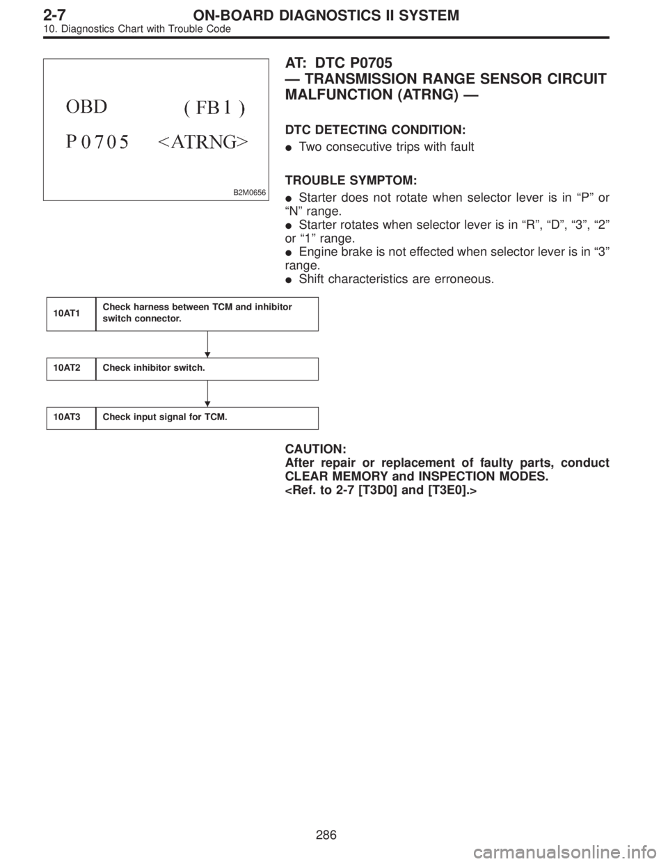
B2M0656
AT: DTC P0705
—TRANSMISSION RANGE SENSOR CIRCUIT
MALFUNCTION (ATRNG)—
DTC DETECTING CONDITION:
�Two consecutive trips with fault
TROUBLE SYMPTOM:
�Starter does not rotate when selector lever is in“P”or
“N”range.
�Starter rotates when selector lever is in“R”,“D”,“3”,“2”
or“1”range.
�Engine brake is not effected when selector lever is in“3”
range.
�Shift characteristics are erroneous.
10AT1Check harness between TCM and inhibitor
switch connector.
10AT2Check inhibitor switch.
10AT3Check input signal for TCM.
CAUTION:
After repair or replacement of faulty parts, conduct
CLEAR MEMORY and INSPECTION MODES.
�
�
286
2-7ON-BOARD DIAGNOSTICS II SYSTEM
10. Diagnostics Chart with Trouble Code
Page 2061 of 2890
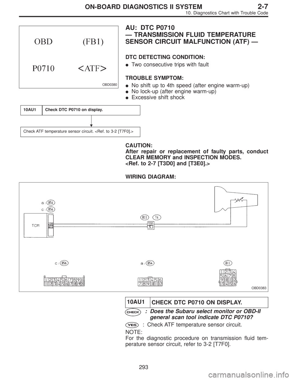
OBD0380
AU: DTC P0710
—TRANSMISSION FLUID TEMPERATURE
SENSOR CIRCUIT MALFUNCTION (ATF)—
DTC DETECTING CONDITION:
�Two consecutive trips with fault
TROUBLE SYMPTOM:
�No shift up to 4th speed (after engine warm-up)
�No lock-up (after engine warm-up)
�Excessive shift shock
10AU1Check DTC P0710 on display.
Check ATF temperature sensor circuit.
CAUTION:
After repair or replacement of faulty parts, conduct
CLEAR MEMORY and INSPECTION MODES.
WIRING DIAGRAM:
OBD0383
10AU1
CHECK DTC P0710 ON DISPLAY.
: Does the Subaru select monitor or OBD-II
general scan tool indicate DTC P0710?
: Check ATF temperature sensor circuit.
NOTE:
For the diagnostic procedure on transmission fluid tem-
perature sensor circuit, refer to 3-2 [T7F0].
�
293
2-7ON-BOARD DIAGNOSTICS II SYSTEM
10. Diagnostics Chart with Trouble Code
Page 2062 of 2890
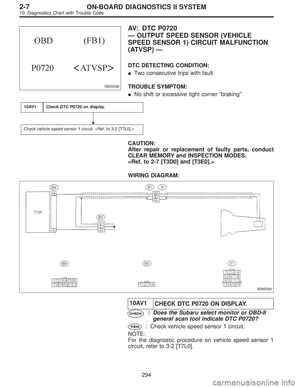
OBD0392
AV: DTC P0720
—OUTPUT SPEED SENSOR (VEHICLE
SPEED SENSOR 1) CIRCUIT MALFUNCTION
(ATVSP)—
DTC DETECTING CONDITION:
�Two consecutive trips with fault
TROUBLE SYMPTOM:
�No shift or excessive tight corner“braking”
10AV1Check DTC P0720 on display.
Check vehicle speed sensor 1 circuit.
CAUTION:
After repair or replacement of faulty parts, conduct
CLEAR MEMORY and INSPECTION MODES.
WIRING DIAGRAM:
B2M0584
10AV1
CHECK DTC P0720 ON DISPLAY.
: Does the Subaru select monitor or OBD-II
general scan tool indicate DTC P0720?
: Check vehicle speed sensor 1 circuit.
NOTE:
For the diagnostic procedure on vehicle speed sensor 1
circuit, refer to 3-2 [T7L0].
�
294
2-7ON-BOARD DIAGNOSTICS II SYSTEM
10. Diagnostics Chart with Trouble Code
Page 2065 of 2890
10BA1Check any other DTC (besides DTC P0731,
P0732, P0733, P0734) on display.
10BA2Check throttle position sensor circuit.
3-2 [T7K0].>
10BA3Check vehicle speed sensor 1 circuit.
3-2 [T7L0].>
10BA4Check vehicle speed sensor 2 circuit.
3-2 [T7M0].>
10BA5Check engine speed input circuit.
CAUTION:
After repair or replacement of faulty parts, conduct
CLEAR MEMORY and INSPECTION MODES.
�
�
�
�
297
2-7ON-BOARD DIAGNOSTICS II SYSTEM
10. Diagnostics Chart with Trouble Code
Page 2067 of 2890
![SUBARU LEGACY 1996 Service Repair Manual 10BA2CHECK THROTTLE POSITION SENSOR
CIRCUIT.
: Is there any trouble in throttle position sen-
sor circuit?
NOTE:
For the diagnostic procedure on throttle position sensor
circuit, refer to 3-2 [T7K0].](/manual-img/17/57433/w960_57433-2066.png "SUBARU LEGACY 1996 Service Repair Manual 10BA2CHECK THROTTLE POSITION SENSOR
CIRCUIT.
: Is there any trouble in throttle position sen-
sor circuit?
NOTE:
For the diagnostic procedure on throttle position sensor
circuit, refer to 3-2 [T7K0].")
10BA2CHECK THROTTLE POSITION SENSOR
CIRCUIT.
: Is there any trouble in throttle position sen-
sor circuit?
NOTE:
For the diagnostic procedure on throttle position sensor
circuit, refer to 3-2 [T7K0].
: Repair or replace throttle position sensor circuit.
: Go to step10BA3.
10BA3CHECK VEHICLE SPEED SENSOR 1 CIR-
CUIT.
: Is there any trouble in vehicle speed sensor
1 circuit?
NOTE:
For the diagnostic procedure on vehicle speed sensor 1
circuit, refer to 3-2 [T7L0].
: Repair or replace vehicle speed sensor 1 circuit.
: Go to step10BA4.
10BA4CHECK VEHICLE SPEED SENSOR 2 CIR-
CUIT.
: Is there any trouble in vehicle speed sensor
2 circuit?
NOTE:
For the diagnostic procedure on vehicle speed sensor 2
circuit, refer to 3-2 [T7M0].
: Repair or replace vehicle speed sensor 2 circuit.
: Go to step10BA5.
10BA5
CHECK ENGINE SPEED INPUT CIRCUIT.
: Is there any trouble in engine speed input
circuit?
NOTE:
For the diagnostic procedure on engine speed input signal
circuit, refer to 3-2 [T7H0].
: Repair or replace engine speed input circuit.
: Go to next.
: Is there poor contact in TCM connector?
: Repair poor contact in TCM connector.
: Go to next.
: Is there any mechanical trouble in automatic
transmission?
: Repair or replace automatic transmission.
: Replace TCM.
299
2-7ON-BOARD DIAGNOSTICS II SYSTEM
10. Diagnostics Chart with Trouble Code
Page 2068 of 2890
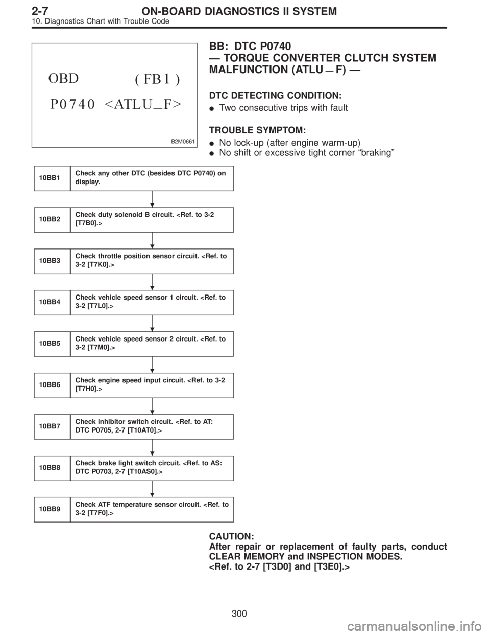
B2M0661
BB: DTC P0740
—TORQUE CONVERTER CLUTCH SYSTEM
MALFUNCTION (ATLU
—F)—
DTC DETECTING CONDITION:
�Two consecutive trips with fault
TROUBLE SYMPTOM:
�No lock-up (after engine warm-up)
�No shift or excessive tight corner“braking”
10BB1Check any other DTC (besides DTC P0740) on
display.
10BB2Check duty solenoid B circuit.
[T7B0].>
10BB3Check throttle position sensor circuit.
3-2 [T7K0].>
10BB4Check vehicle speed sensor 1 circuit.
3-2 [T7L0].>
10BB5Check vehicle speed sensor 2 circuit.
3-2 [T7M0].>
10BB6Check engine speed input circuit.
[T7H0].>
10BB7Check inhibitor switch circuit.
DTC P0705, 2-7 [T10AT0].>
10BB8Check brake light switch circuit.
DTC P0703, 2-7 [T10AS0].>
10BB9Check ATF temperature sensor circuit.
3-2 [T7F0].>
CAUTION:
After repair or replacement of faulty parts, conduct
CLEAR MEMORY and INSPECTION MODES.
�
�
�
�
�
�
�
�
300
2-7ON-BOARD DIAGNOSTICS II SYSTEM
10. Diagnostics Chart with Trouble Code
Page 2070 of 2890
![SUBARU LEGACY 1996 Service Repair Manual 10BB2
CHECK DUTY SOLENOID B CIRCUIT.
: Is there any trouble in duty solenoid B cir-
cuit?
NOTE:
For the diagnostic procedure on duty solenoid B circuit,
refer to 3-2 [T7B0].
: Repair or replace duty s](/manual-img/17/57433/w960_57433-2069.png "SUBARU LEGACY 1996 Service Repair Manual 10BB2
CHECK DUTY SOLENOID B CIRCUIT.
: Is there any trouble in duty solenoid B cir-
cuit?
NOTE:
For the diagnostic procedure on duty solenoid B circuit,
refer to 3-2 [T7B0].
: Repair or replace duty s")
10BB2
CHECK DUTY SOLENOID B CIRCUIT.
: Is there any trouble in duty solenoid B cir-
cuit?
NOTE:
For the diagnostic procedure on duty solenoid B circuit,
refer to 3-2 [T7B0].
: Repair or replace duty solenoid B circuit.
: Go to step10BB3.
10BB3CHECK THROTTLE POSITION SENSOR
CIRCUIT.
: Is there any trouble in throttle position sen-
sor circuit?
NOTE:
For the diagnostic procedure on throttle position sensor
circuit, refer to 3-2 [T7K0].
: Repair or replace throttle position sensor circuit.
: Go to step10BB4.
10BB4CHECK VEHICLE SPEED SENSOR 1 CIR-
CUIT.
: Is there any trouble in vehicle speed sensor
1 circuit?
NOTE:
For the diagnostic procedure on vehicle speed sensor 1
circuit, refer to 3-2 [T7L0].
: Repair or replace vehicle speed sensor 1 circuit.
: Go to step10BB5.
10BB5CHECK VEHICLE SPEED SENSOR 2 CIR-
CUIT.
: Is there any trouble in vehicle speed sensor
2 circuit?
NOTE:
For the diagnostic procedure on vehicle speed sensor 2
circuit, refer to 3-2 [T7M0].
: Repair or replace vehicle speed sensor 2 circuit.
: Go to step10BB6.
10BB6
CHECK ENGINE SPEED INPUT CIRCUIT.
: Is there any trouble in engine speed input
circuit?
NOTE:
For the diagnostic procedure on engine speed input signal
circuit, refer to 3-2 [T7H0].
: Repair or replace engine speed input circuit.
: Go to step10BB7.
302
2-7ON-BOARD DIAGNOSTICS II SYSTEM
10. Diagnostics Chart with Trouble Code
Page 2071 of 2890
![SUBARU LEGACY 1996 Service Repair Manual 10BB7
CHECK INHIBITOR SWITCH CIRCUIT.
: Is there any trouble in inhibitor switch cir-
cuit?
NOTE:
For the diagnostic procedure on inhibitor switch circuit,
refer to 2-7 [T10AT0].
: Repair or replace i](/manual-img/17/57433/w960_57433-2070.png "SUBARU LEGACY 1996 Service Repair Manual 10BB7
CHECK INHIBITOR SWITCH CIRCUIT.
: Is there any trouble in inhibitor switch cir-
cuit?
NOTE:
For the diagnostic procedure on inhibitor switch circuit,
refer to 2-7 [T10AT0].
: Repair or replace i")
10BB7
CHECK INHIBITOR SWITCH CIRCUIT.
: Is there any trouble in inhibitor switch cir-
cuit?
NOTE:
For the diagnostic procedure on inhibitor switch circuit,
refer to 2-7 [T10AT0].
: Repair or replace inhibitor switch circuit.
: Go to step10BB8.
10BB8
CHECK BRAKE LIGHT SWITCH CIRCUIT.
: Is there any trouble in brake light switch cir-
cuit?
NOTE:
For the diagnostic procedure on brake light switch circuit,
refer to 2-7 [T10AS0].
: Repair or replace brake light switch circuit.
: Go to step10BB9.
10BB9CHECK ATF TEMPERATURE SENSOR
CIRCUIT.
: Is there any trouble in ATF temperature sen-
sor circuit?
NOTE:
For the diagnostic procedure on ATF temperature sensor
circuit, refer to 3-2 [T7F0].
: Repair or replace ATF temperature sensor circuit.
: Go to next.
: Is there poor contact in TCM connector?
: Repair poor contact in TCM connector.
: Go to next.
: Is there any mechanical trouble in automatic
transmission?
: Repair or replace automatic transmission.
: Replace TCM.
303
2-7ON-BOARD DIAGNOSTICS II SYSTEM
10. Diagnostics Chart with Trouble Code
![SUBARU LEGACY 1996 Service Repair Manual 10BA1Check any other DTC (besides DTC P0731,
P0732, P0733, P0734) on display.
10BA2Check throttle position sensor circuit. <Ref. to
3-2 [T7K0].>
10BA3Check vehicle speed sensor 1 circuit. <Ref. to
3-2](/manual-img/17/57433/w960_57433-2064.png "SUBARU LEGACY 1996 Service Repair Manual 10BA1Check any other DTC (besides DTC P0731,
P0732, P0733, P0734) on display.
10BA2Check throttle position sensor circuit. <Ref. to
3-2 [T7K0].>
10BA3Check vehicle speed sensor 1 circuit. <Ref. to
3-2")