Page 1984 of 2890
 Turn ignition switch to OFF.
2) Disconnect connector from crankshaft position sensor.
3) Measure resistance of ha")
OBD0718A
10AB1CHECK HARNESS BETWEEN CRANK-
SHAFT POSITION SENSOR AND ECM
CONNECTOR.
1) Turn ignition switch to OFF.
2) Disconnect connector from crankshaft position sensor.
3) Measure resistance of harness between crankshaft
position sensor connector and engine ground.
: Connector & terminal
(E10) No. 1—Engine ground:
Is the resistance more than 100 kΩ?
: Repair harness and connector.
NOTE:
In this case, repair the following:
�Open circuit in harness between crankshaft position
sensor and ECM connector
�Poor contact in ECM connector
�Poor contact in coupling connector (B20)
: Go to next.
OBD0718A
: Connector & terminal
(E10) No. 1—Engine ground:
Is the resistance less than 10Ω?
: Repair short circuit in harness between crankshaft
position sensor and ECM connector.
NOTE:
The harness between both connectors are shielded.
Repair short circuit in harness together with shield.
: Go to next.
OBD0719A
: Connector & terminal
(E10) No. 2—Engine ground:
Is the resistance less than 5Ω?
: Go to step10AB2.
: Repair harness and connector.
NOTE:
In this case, repair the following:
�Open circuit in harness between crankshaft position
sensor and ECM connector
�Poor contact in ECM connector
�Poor contact in coupling connector (B20)
216
2-7ON-BOARD DIAGNOSTICS II SYSTEM
10. Diagnostics Chart with Trouble Code
Page 1985 of 2890
10AB2CHECK CRANKSHAFT POSITION SEN-
SOR.
: Is the crankshaft position sensor installa-
tion bolt tightened securely?
: Go to next step 1).
: Tighten crankshaft position sensor installation bolt
securely.
G2M0639
1) Remove crankshaft position sensor.
2) Measure resistance between connector terminals of
crankshaft position sensor.
: Terminals
No. 1—No. 2:
Is the resistance between 1 and 4 kΩ?
: Repair poor contact in crankshaft position sensor
connector.
: Replace crankshaft position sensor.
217
2-7ON-BOARD DIAGNOSTICS II SYSTEM
10. Diagnostics Chart with Trouble Code
Page 1986 of 2890
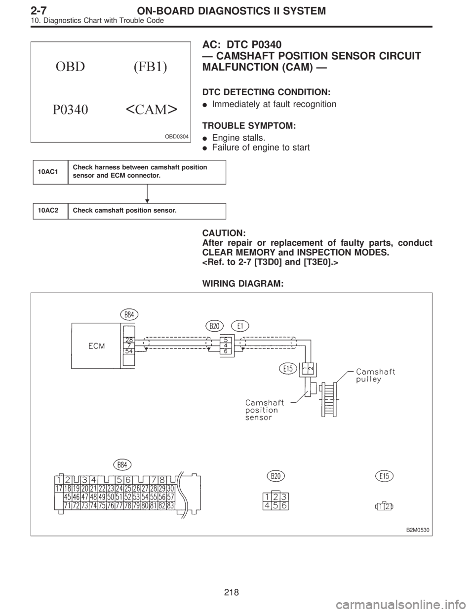
OBD0304
AC: DTC P0340
—CAMSHAFT POSITION SENSOR CIRCUIT
MALFUNCTION (CAM)—
DTC DETECTING CONDITION:
�Immediately at fault recognition
TROUBLE SYMPTOM:
�Engine stalls.
�Failure of engine to start
10AC1Check harness between camshaft position
sensor and ECM connector.
10AC2Check camshaft position sensor.
CAUTION:
After repair or replacement of faulty parts, conduct
CLEAR MEMORY and INSPECTION MODES.
WIRING DIAGRAM:
B2M0530
�
218
2-7ON-BOARD DIAGNOSTICS II SYSTEM
10. Diagnostics Chart with Trouble Code
Page 1987 of 2890
 Turn ignition switch to OFF.
2) Disconnect connector from camshaft position sensor.
3) Measure resistance of harnes")
OBD0720A
10AC1CHECK HARNESS BETWEEN CAM-
SHAFT POSITION SENSOR AND ECM
CONNECTOR.
1) Turn ignition switch to OFF.
2) Disconnect connector from camshaft position sensor.
3) Measure resistance of harness between camshaft posi-
tion sensor connector and engine ground.
: Connector & terminal
(E15) No. 1—Engine ground:
Is the resistance more than 100 kΩ?
: Repair harness and connector.
NOTE:
In this case, repair the following:
�Open circuit in harness between camshaft position sen-
sor and ECM connector
�Poor contact in ECM connector
�Poor contact in coupling connector (B20)
: Go to next.
OBD0720A
: Connector & terminal
(E15) No. 1—Engine ground:
Is the resistance less than 10Ω?
: Repair short circuit in harness between camshaft
position sensor connector and ECM connector.
NOTE:
The harness between both connectors are shielded.
Repair short circuit in harness together with shield.
: Go to next.
OBD0721A
: Connector & terminal
(E15) No. 2—Engine ground:
Is the resistance less than 5Ω?
: Go to step10AC2.
: Repair harness and connector.
NOTE:
In this case, repair the following:
�Open circuit in harness between camshaft position sen-
sor and ECM connector
�Poor contact in ECM connector
�Poor contact in coupling connector (B20)
219
2-7ON-BOARD DIAGNOSTICS II SYSTEM
10. Diagnostics Chart with Trouble Code
Page 1988 of 2890
10AC2
CHECK CAMSHAFT POSITION SENSOR.
: Is the camshaft position sensor installation
bolt tightened securely?
: Go to next step 1).
: Tighten camshaft position sensor installation bolt
securely.
G2M0639
1) Remove camshaft position sensor.
2) Measure resistance between connector terminals of
camshaft position sensor.
: Terminals
No. 1—No. 2:
Is the resistance between 1 and 4 kΩ?
: Repair poor contact in camshaft position sensor
connector.
: Replace camshaft position sensor.
220
2-7ON-BOARD DIAGNOSTICS II SYSTEM
10. Diagnostics Chart with Trouble Code
Page 2023 of 2890
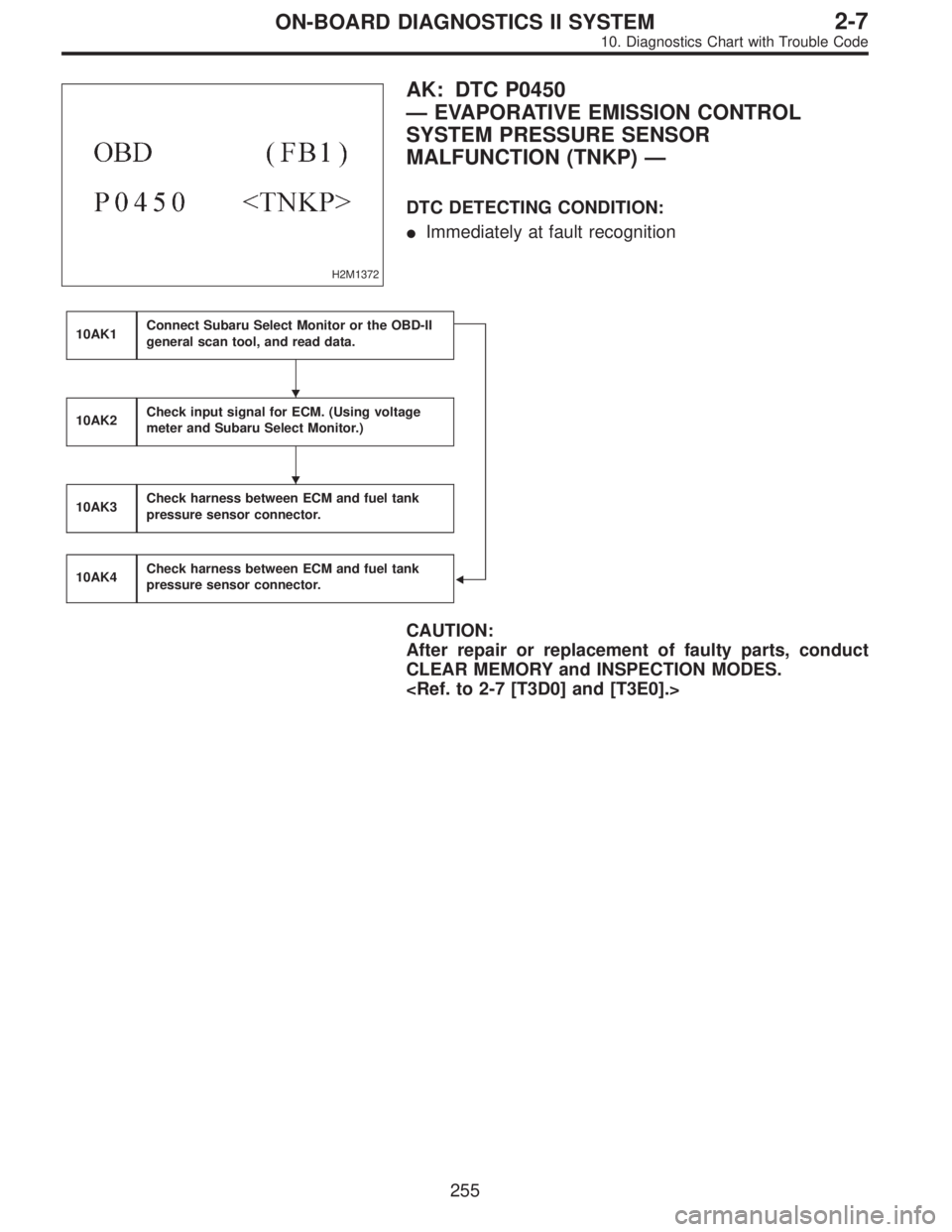
H2M1372
AK: DTC P0450
—EVAPORATIVE EMISSION CONTROL
SYSTEM PRESSURE SENSOR
MALFUNCTION (TNKP)—
DTC DETECTING CONDITION:
�Immediately at fault recognition
10AK1Connect Subaru Select Monitor or the OBD-II
general scan tool, and read data.
�
10AK2Check input signal for ECM. (Using voltage
meter and Subaru Select Monitor.)
10AK3Check harness between ECM and fuel tank
pressure sensor connector.
10AK4Check harness between ECM and fuel tank
pressure sensor connector.
CAUTION:
After repair or replacement of faulty parts, conduct
CLEAR MEMORY and INSPECTION MODES.
�
�
255
2-7ON-BOARD DIAGNOSTICS II SYSTEM
10. Diagnostics Chart with Trouble Code
Page 2026 of 2890
 Turn ignition switch to OFF.
2) Remove fuel filler cap.
3) Install fuel filler cap.
4) Connect Subaru Sel")
OBD0145A
10AK1CONNECT SUBARU SELECT MONITOR
OR THE OBD-II GENERAL SCAN TOOL,
AND READ DATA.
1) Turn ignition switch to OFF.
2) Remove fuel filler cap.
3) Install fuel filler cap.
4) Connect Subaru Select Monitor or the OBD-II general
scan tool to data link connector.
5) Turn ignition switch to ON and Subaru Select Monitor or
the OBD-II general scan tool switch to ON.
H2M1326
6) Read the data on Subaru Select Monitor or the OBD-II
general scan tool.
�Subaru Select Monitor
Designate mode using function key.
Function mode: F43
�F43: Display shows pressure signal value sent from fuel
tank pressure sensor.
: Is the value less than�2.8 kPa in function
mode F43?
: Go to step10AK2.
: Go to next.
H2M1326
: Is the value more than 2.8 kPa in function
mode F43?
: Go to step10AK4.
: Repair harness and connector.
NOTE:
In this case, repair the following:
�Open or short circuit in harness between fuel tank pres-
sure sensor and ECM connector
�Poor contact in coupling connectors (B97, and B98 (LHD
only))
�Poor contact in fuel tank pressure sensor
�Poor contact in ECM connector
�OBD-II general scan tool
For detailed operation procedures, refer to the OBD-II Gen-
eral Scan Tool Instruction Manual.
258
2-7ON-BOARD DIAGNOSTICS II SYSTEM
10. Diagnostics Chart with Trouble Code
Page 2027 of 2890
B2M0535A
10AK2CHECK INPUT SIGNAL FOR ECM.
(USING VOLTAGE METER AND SUBARU
SELECT MONITOR.)
1) Measure voltage between ECM connector and chassis
ground.
: Connector & terminal
(B84) No. 21 (+)—Chassis ground (�):
Is the voltage more than 4.5 V?
: Go to next step 2).
: Go to next.
B2M0535A
: Does the voltage change more than 4.5 V by
shaking harness and connector of ECM
while monitoring the value with voltage
meter?
: Repair poor contact in ECM connector.
: Replace ECM.
H2M1374B
2) Measure voltage between ECM and chassis ground.
: Connector & terminal
(B84) No. 4 (+)—Chassis ground (�):
Is the voltage less than 0.2 V?
: Go to step10AK3.
: Go to next step 3).
H2M1326
3) Read data on Subaru Select Monitor.
�Subaru Select Monitor
Designate mode using function key.
Function mode: F43
�F43: Display shows pressure signal value sent from fuel
tank pressure sensor.
259
2-7ON-BOARD DIAGNOSTICS II SYSTEM
10. Diagnostics Chart with Trouble Code
.
: Tighten crankshaft position sensor installation bolt
secure")
.
: Tighten camshaft position sensor installation bolt
securely.
G2M06")

1) Measure voltage between ECM connector and chassis
ground.
: Connector & terminal
(B84) No. 21 (+)—Chassi")