Page 1947 of 2890
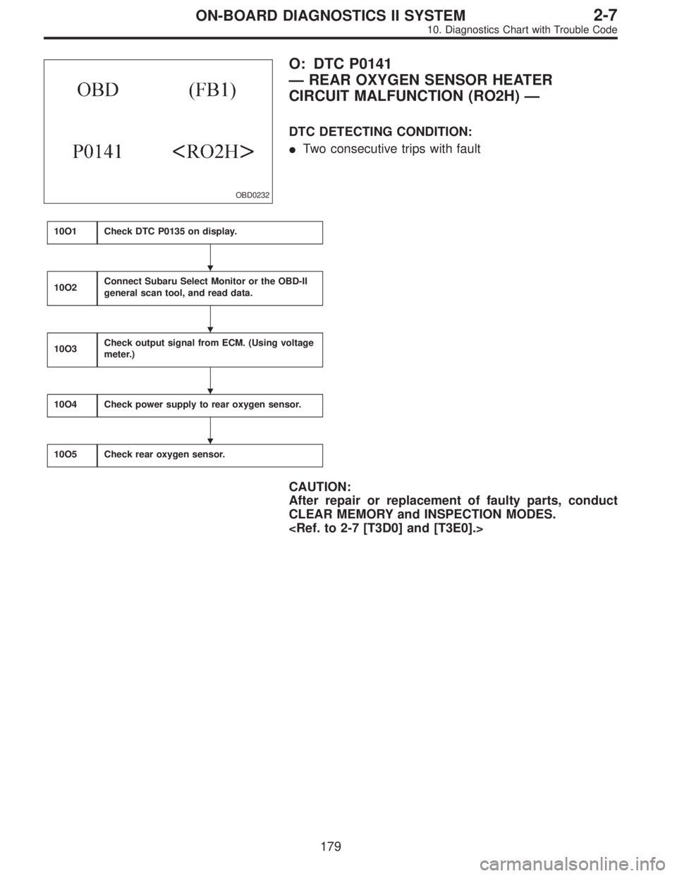
OBD0232
O: DTC P0141
—REAR OXYGEN SENSOR HEATER
CIRCUIT MALFUNCTION (RO2H)—
DTC DETECTING CONDITION:
�Two consecutive trips with fault
10O1Check DTC P0135 on display.
10O2Connect Subaru Select Monitor or the OBD-II
general scan tool, and read data.
10O3Check output signal from ECM. (Using voltage
meter.)
10O4Check power supply to rear oxygen sensor.
10O5Check rear oxygen sensor.
CAUTION:
After repair or replacement of faulty parts, conduct
CLEAR MEMORY and INSPECTION MODES.
�
�
�
�
179
2-7ON-BOARD DIAGNOSTICS II SYSTEM
10. Diagnostics Chart with Trouble Code
Page 1950 of 2890
 Turn ignition switch to OFF.
2) Disconnect connector from ECM.
3) Measure resistance of harness between ECM connec-
tor and chassis ground.
: Connector & terminal
(B84) No. 42—Chassis gr")
B2M0553A
1) Turn ignition switch to OFF.
2) Disconnect connector from ECM.
3) Measure resistance of harness between ECM connec-
tor and chassis ground.
: Connector & terminal
(B84) No. 42—Chassis ground:
Is the resistance less than 5Ω?
: Repair poor contact in ECM connector.
: Repair harness and connector.
NOTE:
In this case, repair the following:
�Open circuit in harness between ECM and coupling con-
nector (B22)
�Open circuit in harness between coupling connector
(B22) and engine grounding terminal
�Poor contact in rear oxygen sensor connector
�Poor contact in rear oxygen sensor connecting harness
connector (B19)
�Poor contact in coupling connector (B22)
OBD0145A
10O2CONNECT SUBARU SELECT MONITOR
OR THE OBD-II GENERAL SCAN TOOL,
AND READ DATA.
1) Turn ignition switch to OFF.
2) Connect Subaru Select Monitor or the OBD-II general
scan tool to data link connector.
3) Turn ignition switch to ON and Subaru Select Monitor or
OBD-II general scan tool switch to ON.
4) Start engine.
B2M0498
5) Read data on Subaru Select Monitor or OBD-II general
scan tool.
�Subaru Select Monitor
Designate mode using function key.
Function mode: F33
�F33: Rear oxygen sensor heater current is indicated.
: Is the value more than 0.2 A in function
mode F33?
: Repair connector.
NOTE:
In this case, repair the following:
�Poor contact in rear oxygen sensor connector
�Poor contact in rear oxygen sensor connecting harness
connector
�Poor contact in ECM connector
: Go to step10O3.
�OBD-II scan tool
For detailed operation procedures, refer to the OBD-II Gen-
eral Scan Tool Instruction Manual.
182
2-7ON-BOARD DIAGNOSTICS II SYSTEM
10. Diagnostics Chart with Trouble Code
Page 1951 of 2890
B2M0554A
10O3CHECK OUTPUT SIGNAL FROM ECM.
(USING VOLTAGE METER.)
1) Start and idle the engine.
2) Measure voltage between ECM connector and chassis
ground.
: Connector & terminal
(B84) No. 37 (+)—Chassis ground (�):
Is the voltage less than 1.0 V?
: Go to step10O4.
: Go to next.
: Does the voltage change less than 1.0 V by
shaking harness and connector of ECM
while monitoring the value with voltage
meter?
: Repair poor contact in ECM connector.
: Go to next step 3).
B2M0554A
3) Disconnect connector from rear oxygen sensor.
4) Measure voltage between ECM connector and chassis
ground.
: Connector & terminal
(B84) No. 37 (+)—Chassis ground (�):
Is the voltage less than 1.0 V?
: Replace ECM.
: Repair short circuit in harness between ECM and
rear oxygen sensor connector. After repair short
circuit in harness, replace ECM.
183
2-7ON-BOARD DIAGNOSTICS II SYSTEM
10. Diagnostics Chart with Trouble Code
Page 1952 of 2890
 Turn ignition switch to OFF.
2) Disconnect connector from rear oxygen sensor.
3) Turn ignition switch to ON.
4) Measure voltage between rear")
OBD0710C
10O4CHECK POWER SUPPLY TO REAR OXY-
GEN SENSOR.
1) Turn ignition switch to OFF.
2) Disconnect connector from rear oxygen sensor.
3) Turn ignition switch to ON.
4) Measure voltage between rear oxygen sensor connec-
tor and engine ground or chassis ground.
: Connector & terminal
�2200 cc California model
(B19) No. 2 (+)—Engine ground (�):
�Except 2200 cc California model
(T6) No. 2 (+)—Chassis ground (�):
Is the voltage more than 10 V?
: Go to step10O5.
: Repair power supply line.
NOTE:
In this case, repair the following:
�Open circuit in harness between main relay and rear
oxygen sensor connector
�Poor contact in rear oxygen sensor connector
�Poor contact in rear oxygen sensor connecting harness
connector (Except 2200 cc California model)
OBD0706
10O5
CHECK REAR OXYGEN SENSOR.
1) Turn ignition switch to OFF.
2) Measure resistance between rear oxygen sensor con-
nector terminals.
: Terminals
No. 1—No. 2:
Is the resistance less than 30Ω?
: Repair harness and connector.
NOTE:
In this case, repair the following:
�Open circuit in harness between rear oxygen sensor and
ECM connector
�Poor contact in rear oxygen sensor connector
�Poor contact in ECM connector
�Poor contact in rear oxygen sensor connecting harness
connector
: Replace rear oxygen sensor.
184
2-7ON-BOARD DIAGNOSTICS II SYSTEM
10. Diagnostics Chart with Trouble Code
Page 1953 of 2890
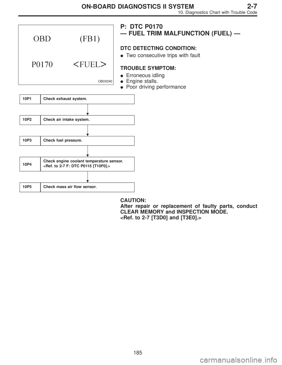
OBD0240
P: DTC P0170
—FUEL TRIM MALFUNCTION (FUEL)—
DTC DETECTING CONDITION:
�Two consecutive trips with fault
TROUBLE SYMPTOM:
�Erroneous idling
�Engine stalls.
�Poor driving performance
10P1Check exhaust system.
10P2Check air intake system.
10P3Check fuel pressure.
10P4Check engine coolant temperature sensor.
10P5Check mass air flow sensor.
CAUTION:
After repair or replacement of faulty parts, conduct
CLEAR MEMORY and INSPECTION MODE.
�
�
�
�
185
2-7ON-BOARD DIAGNOSTICS II SYSTEM
10. Diagnostics Chart with Trouble Code
Page 1956 of 2890
OBD0145A
10P4CHECK ENGINE COOLANT TEMPERA-
TURE SENSOR.
1) Turn ignition switch to OFF.
2) Connect the Subaru Select Monitor or the OBD-II gen-
eral scan tool to data link connector.
3) Start the engine and warm-up completely.
B2M0479
4) Read data on Subaru Select Monitor or the OBD-II gen-
eral scan tool.
�Subaru Select Monitor
Designate mode using function key.
Function mode: F04
�F04: Water temperature is indicated in“°C”and“°F”.
: Is temperature greater than 60°Cor140°Fin
function mode F04?
: Go to step10P5.
: Replace engine coolant temperature sensor.
�OBD-II general scan tool
For detailed operation procedures, refer to the OBD-II Gen-
eral Scan Tool Instruction Manual.
188
2-7ON-BOARD DIAGNOSTICS II SYSTEM
10. Diagnostics Chart with Trouble Code
Page 1957 of 2890
 Turn ignition switch to OFF.
2) Connect the Subaru Select Monitor or the OBD-II gen-
eral scan tool to data link connector.
3) Start the engine and warm-up")
OBD0145A
10P5
CHECK MASS AIR FLOW SENSOR.
1) Turn ignition switch to OFF.
2) Connect the Subaru Select Monitor or the OBD-II gen-
eral scan tool to data link connector.
3) Start the engine and warm-up engine until coolant tem-
perature is greater than 60°C (140°F).
4) Place the selector lever in“N”or“P”position.
5) Turn A/C switch to OFF.
6) Turn all accessory switches to OFF.
B2M0481
7) Read data on Subaru Select Monitor or OBD-II general
scan tool.
�Subaru Select Monitor
Designate mode using function key.
Function mode: F06
�F06: Mass air flow and voltage input from mass air flow
sensor are shown on display.
: Is the voltage in function mode F06 within
the specifications shown in the following
table?
Model Engine speed Specified value
2200 ccIdling 1.7—3.3 (g/sec)
2,500 rpm 7.1—14.2 (g/sec)
2500 ccIdling 2.2—4.2 (g/sec)
2,500 rpm 8.6—14.5 (g/sec)
: Contact with SOA service.
NOTE:
Inspection by DTM is required, because probable cause is
deterioration of multiple parts.
: Replace mass air flow sensor.
�OBD-II general scan tool
For detailed operation procedures, refer to the OBD-II Gen-
eral Scan Tool Instruction Manual.
189
2-7ON-BOARD DIAGNOSTICS II SYSTEM
10. Diagnostics Chart with Trouble Code
Page 1958 of 2890
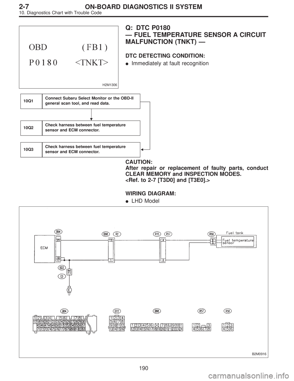
H2M1306
Q: DTC P0180
—FUEL TEMPERATURE SENSOR A CIRCUIT
MALFUNCTION (TNKT)—
DTC DETECTING CONDITION:
�Immediately at fault recognition
10Q1Connect Subaru Select Monitor or the OBD-II
general scan tool, and read data.
�
10Q2Check harness between fuel temperature
sensor and ECM connector.
10Q3Check harness between fuel temperature
sensor and ECM connector.
CAUTION:
After repair or replacement of faulty parts, conduct
CLEAR MEMORY and INSPECTION MODES.
WIRING DIAGRAM:
�LHD Model
B2M0916
�
190
2-7ON-BOARD DIAGNOSTICS II SYSTEM
10. Diagnostics Chart with Trouble Code

1) Start and idle the engine.
2) Measure voltage between ECM connector and chassis
ground.
: Connector & terminal
(B84) No. 37 (+)—C")
![SUBARU LEGACY 1996 Service Repair Manual OBD0145A
10P4CHECK ENGINE COOLANT TEMPERA-
TURE SENSOR.
<REF. TO 2-7 F: DTC P0115 [T10F0].>
1) Turn ignition switch to OFF.
2) Connect the Subaru Select Monitor or the OBD-II gen-
eral scan tool to da](/manual-img/17/57433/w960_57433-1955.png "SUBARU LEGACY 1996 Service Repair Manual OBD0145A
10P4CHECK ENGINE COOLANT TEMPERA-
TURE SENSOR.
<REF. TO 2-7 F: DTC P0115 [T10F0].>
1) Turn ignition switch to OFF.
2) Connect the Subaru Select Monitor or the OBD-II gen-
eral scan tool to da")