Page 2190 of 2890
 Install combination meter.
(2) Connect connector to TCM.
(3) Lift-up the vehicle and place safety stand.
WARNING:
On AWD models, make sure that all wheels are raised
o")
B3M0257
�Using oscilloscope:
(1) Install combination meter.
(2) Connect connector to TCM.
(3) Lift-up the vehicle and place safety stand.
WARNING:
On AWD models, make sure that all wheels are raised
off floor.
(4) Set oscilloscope to vehicle speed sensor 2.
Connector & terminal / No. 1—No. 2
B3M0254A
(5) Push the TCS OFF switch to ON. (With TCS mod-
els)
(6) Start the engine, and drive the wheels slowly.
(7) Measure signal voltage indicated on oscilloscope.
Specified voltage: AC 2 V, or more
NOTE:
The speed difference between front and rear wheels may
light either the ABS or the ABS/TCS warning light, but this
indicates no malfunctions. When AT control diagnosis is
finished, perform the ABS or the ABS/TCS memory clear-
ance procedure of self-diagnosis system.
B3M0369A
4. CHECK INPUT SIGNAL FOR TCM.
1) Connect connector to vehicle speed sensor 2.
2) Lift-up the vehicle or set the vehicle on free roller.
CAUTION:
On AWD models, raise all wheels off floor.
3) Push the TCS OFF switch to ON. (With TCS models)
4) Start the engine, and drive the wheels slowly.
5) Measure voltage between TCM and body.
Connector & terminal / Specified voltage:
(B56) No. 11—Body / Less than 1↔
more than 9 V
NOTE:
The speed difference between front and rear wheels may
light either the ABS or the ABS/TCS warning light, but this
indicates no malfunctions. When AT control diagnosis is
finished, perform the ABS or the ABS/TCS memory clear-
ance procedure of self-diagnosis system.
50
3-2AUTOMATIC TRANSMISSION AND DIFFERENTIAL
7. Diagnostic Chart with Trouble Code
Page 2191 of 2890
 Install combination meter.
(2) Connect connectors to TCM and vehicle speed
sensor 2.
(3) Lift-up the vehicle or set the vehicle on free roller.
(4) Turn igni")
OBD0145A
�Using Subaru select monitor:
(1) Install combination meter.
(2) Connect connectors to TCM and vehicle speed
sensor 2.
(3) Lift-up the vehicle or set the vehicle on free roller.
(4) Turn ignition switch to OFF.
(5) Connect the Subaru select monitor to data link con-
nector.
(6) Turn ignition switch to ON and Subaru select moni-
tor switch to ON.
CAUTION:
On AWD models, raise all wheels off floor.
(7) Push the TCS OFF switch to ON. (With TCS mod-
els)
G3M0726
B3M0384
(8) Start the engine, and drive the wheels.
(9) Read data on Subaru select monitor.
(10) Designate mode using function key.
Function mode: F04 or F05
SPECIFIED DATA:
Compare speedometer with select monitor indica-
tions.
�F04: Vehicle speed is indicated in mile per hour (MPH).
�F05: Vehicle speed is indicated in kilometer per hour
(km/h).
NOTE:
The speed difference between front and rear wheels may
light either the ABS or the ABS/TCS warning light, but this
indicates no malfunctions. When AT control diagnosis is
finished, perform the ABS or the ABS/TCS memory clear-
ance procedure of self-diagnosis system.
B3M0248B
�Using oscilloscope:
(1) Connect connector to vehicle speed sensor 2.
(2) Lift-up the vehicle or set the vehicle on free rollers.
CAUTION:
On AWD models, raise all wheels off floor.
(3) Set oscilloscope to TCM connector terminals.
Connector & terminals:
Positive probe; (B56) No. 11
Earth lead; Body
51
3-2AUTOMATIC TRANSMISSION AND DIFFERENTIAL
7. Diagnostic Chart with Trouble Code
Page 2193 of 2890
8. Diagnostic Chart with Select Monitor
A: BASIC DIAGNOSTIC CHART
If no trouble codes appear in the on-board diagnostic
operation (although problems have occurred or are
occurring), measure performance characteristics of
sensors, actuators, etc., in the“F”mode (select monitor
function), and compare with the“basic data”to determine
the cause of problems.
Trouble occurs.
No trouble codes appear in on-board diagnostic operation.
Measure each item in select mode function.
Compare measured values with basic data.
Determine item which is outside basic data specifications.
Check sensor and actuator affected.
�
�
�
�
�
53
3-2AUTOMATIC TRANSMISSION AND DIFFERENTIAL
8. Diagnostic Chart with Select Monitor
Page 2194 of 2890
 56
F01 Battery voltage VB V Battery voltage")
B: LIST OF OUTPUT MODES
1. FUNCTION MODE
Mode Contents Abbr. Unit Contents of display Page
F00 Mode display——AT or EGI mode (when monitor is connected.) 56
F01 Battery voltage VB V Battery voltage applied to control unit. 56
F02 Vehicle speed sensor 1 VSP1 m/h Vehicle speed (miles/h) sent from vehicle speed sensor 1. 57
F03 Vehicle speed sensor 1 VSP1 km/h Vehicle speed (km/h) sent from vehicle speed sensor 1. 57
F04 Vehicle speed sensor 2 VSP2 m/h Vehicle speed (miles/h) sent from vehicle speed sensor 2. 57
F05 Vehicle speed sensor 2 VSP2 km/h Vehicle speed (km/h) sent from vehicle speed sensor 2. 57
F06 Engine speed EREV rpm Engine speed sent from ECM. 58
F07 ATF temperature sensor ATFT°F ATF temperature (°F) sent from ATF temperature sensor. 58
F08 ATF temperature sensor ATFT°C ATF temperature (°C) sent from ATF temperature sensor. 58
F09 Throttle position sensor THV V Voltage sent from throttle position sensor. 59
F10 Gear position GEAR—Transmission gear position 59
F11 Line pressure duty PLDTY % Duty ratio flowing through duty solenoid A. 60
F12 Lock-up duty LUDTY % Duty ratio flowing through duty solenoid B. 61
F13 AWD duty 4WDTY % Duty ratio flowing through duty solenoid C. 62
F14Throttle position sensor
power supplyTHVCC V Power supply voltage to throttle position sensor 63
F15 Mass air flow signal AFM V Output voltage from air flow sensor 63
54
3-2AUTOMATIC TRANSMISSION AND DIFFERENTIAL
8. Diagnostic Chart with Select Monitor
Page 2197 of 2890
G3M0725
E: MODE F02
—VEHICLE SPEED SENSOR 1 (VSP1)—
F03 = vehicle speed (VSP1):
to be indicated in“km/h”.
CONDITION:
Raise vehicle off ground and operate at constant speed.
SPECIFIED DATA:
Compare speedometer with monitor indications.
Probable cause (if outside“specified data”)
1. Vehicle speed sensor 1
�Check performance characteristics of vehicle speed
sensor 1.
OK
Check TCM and replace if necessary.
G3M0726
F: MODE F04
—VEHICLE SPEED SENSOR 2 (VSP2)—
F05 = vehicle speed (VSP2):
to be indicated in“km/h”.
CONDITION:
Raise vehicle off ground and operate at constant speed.
SPECIFIED DATA:
Compare speedometer with monitor indications.
Probable cause (if outside“specified data”)
1. Vehicle speed sensor 2
�Check performance characteristics of vehicle speed
sensor 2.
OK
Check TCM and replace if necessary.
�
�
57
3-2AUTOMATIC TRANSMISSION AND DIFFERENTIAL
8. Diagnostic Chart with Select Monitor
Page 2198 of 2890
—
CONDITION:
Measure with engine operating at constant speed.
SPECIFIED DATA:
Same as tachometer reading (in combination meter)
Probable cause (if outside“")
G3M0727
G: MODE F06—ENGINE SPEED (EREV)—
CONDITION:
Measure with engine operating at constant speed.
SPECIFIED DATA:
Same as tachometer reading (in combination meter)
Probable cause (if outside“specified data”)
1. Conduct diagnostics in relation to MPFI
system for engine speed.
�OK
Check TCM and replace if necessary.
OBD0386
H: MODE F07
—ATF TEMPERATURE SENSOR (ATFT)—
F08 = ATF temperature (ATFT):
to be indicated in“deg C”.
CONDITION:
�Low ATF temperature (before engine/vehicle starts.)
�High ATF temperature (after driving vehicle for warm-
up.)
SPECIFIED DATA:
�Ambient temperature: ±50°F (±10°C)
(Low ATF temperature)
�ATF temperature: 158—230°F (70—11 0°C)
(High ATF temperature)
�Open harness: 176 deg F (80 deg C)
�Shorted harness: 320 deg F (160 deg C)
Probable cause (if outside“specified data”)
1. ATF temperature sensor
�Check performance characteristics of ATF
temperature sensor.
OK
Check TCM and replace if necessary.
�
58
3-2AUTOMATIC TRANSMISSION AND DIFFERENTIAL
8. Diagnostic Chart with Select Monitor
Page 2199 of 2890
—
CONDITION:
�Ignition switch ON (with engine OFF)
�Measure voltage while operating throttle valve from a
fully closed position to a fully open p")
B3M0383
I: MODE F09
—THROTTLE POSITION SENSOR (THV)—
CONDITION:
�Ignition switch ON (with engine OFF)
�Measure voltage while operating throttle valve from a
fully closed position to a fully open position.
SPECIFIED DATA:
�Fully closed position: 0.5±0.2 V
�Fully open position: 4.6±0.3 V
�From fully closed to fully open position:
Voltage must smoothly decrease.
�Open harness: 5.0±0.3 V
�Shorted harness: 0.00 V
Probable cause (if outside“specified data”)
1. Throttle position sensor
�Check performance characteristics of throttle
position sensor.
OK
Check TCM and replace if necessary.
G3M0730
J: MODE F10—GEAR POSITION (GEAR)—
CONDITION:
Check while driving vehicle (after warm-up).
SPECIFIED DATA:
Gear position (Refer to shift performance characteristics
chart.)
Probable cause (item outside“specified data”)
1. Shift solenoid 1
�Check performance characteristics of shift solenoid
1.
OK
2. Shift solenoid 2
�Check performance characteristics of shift solenoid
2.
OK
3. Shift solenoid 3
�Check performance characteristics of shift solenoid
3.
OK
Check TCM and replace as necessary.
�
�
�
�
59
3-2AUTOMATIC TRANSMISSION AND DIFFERENTIAL
8. Diagnostic Chart with Select Monitor
Page 2200 of 2890
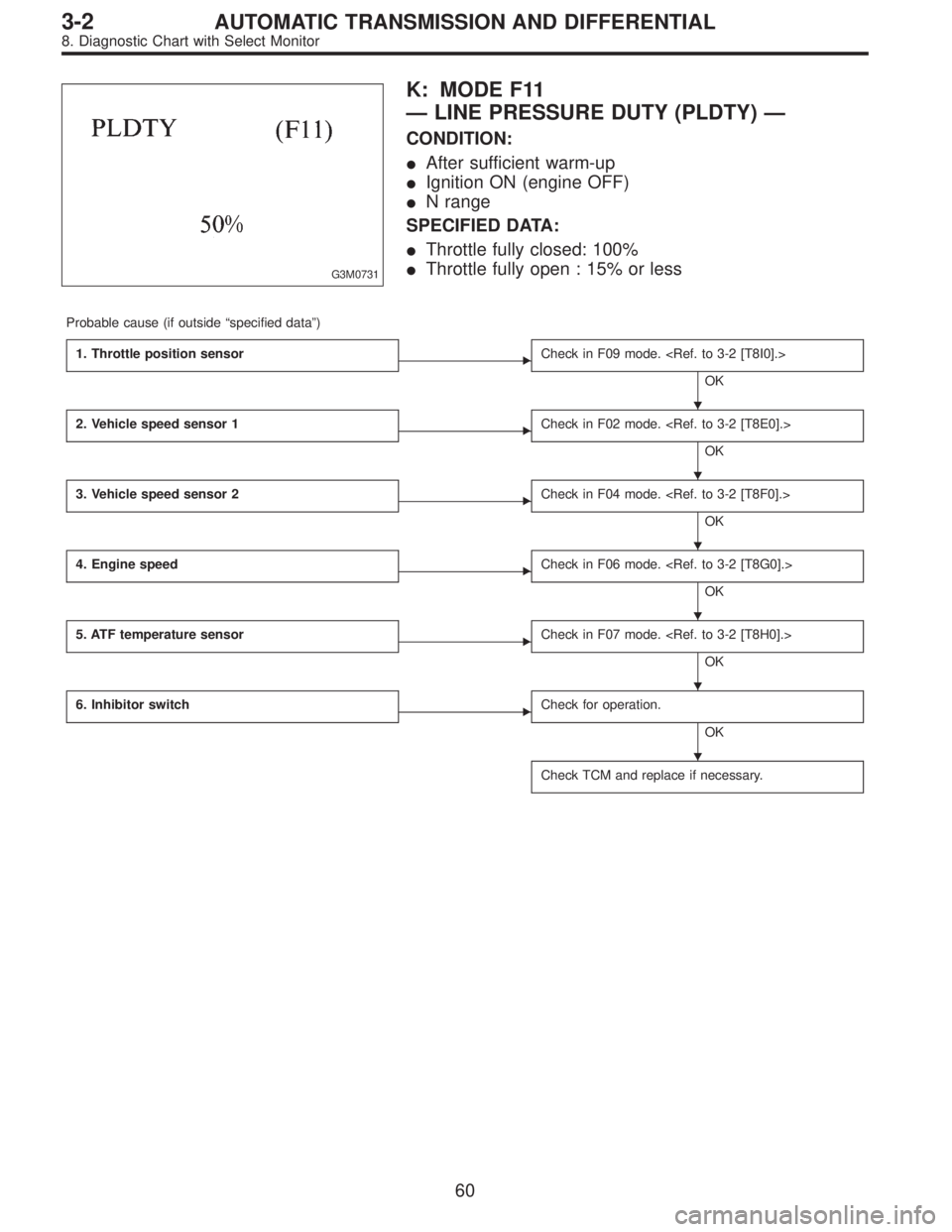
G3M0731
K: MODE F11
—LINE PRESSURE DUTY (PLDTY)—
CONDITION:
�After sufficient warm-up
�Ignition ON (engine OFF)
�N range
SPECIFIED DATA:
�Throttle fully closed: 100%
�Throttle fully open : 15% or less
Probable cause (if outside“specified data”)
1. Throttle position sensor
�Check in F09 mode.
OK
2. Vehicle speed sensor 1
�Check in F02 mode.
OK
3. Vehicle speed sensor 2
�Check in F04 mode.
OK
4. Engine speed
�Check in F06 mode.
OK
5. ATF temperature sensor
�Check in F07 mode.
OK
6. Inhibitor switch
�Check for operation.
OK
Check TCM and replace if necessary.
�
�
�
�
�
�
60
3-2AUTOMATIC TRANSMISSION AND DIFFERENTIAL
8. Diagnostic Chart with Select Monitor
, measure performanc")
—
F03 = vehicle speed (VSP1):
to be indicated in“km/h”.
CONDITION:
Raise vehicle off ground and operate at constant speed.
SPECIFIED DATA:
Com")