Page 2201 of 2890
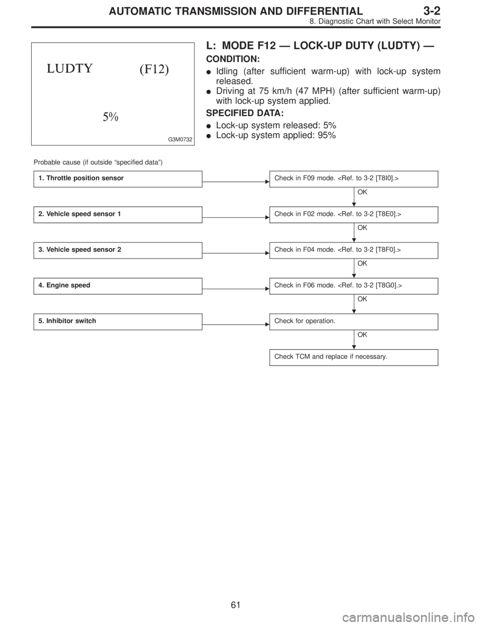
G3M0732
L: MODE F12—LOCK-UP DUTY (LUDTY)—
CONDITION:
�Idling (after sufficient warm-up) with lock-up system
released.
�Driving at 75 km/h (47 MPH) (after sufficient warm-up)
with lock-up system applied.
SPECIFIED DATA:
�Lock-up system released: 5%
�Lock-up system applied: 95%
Probable cause (if outside“specified data”)
1. Throttle position sensor
�Check in F09 mode.
OK
2. Vehicle speed sensor 1
�Check in F02 mode.
OK
3. Vehicle speed sensor 2
�Check in F04 mode.
OK
4. Engine speed
�Check in F06 mode.
OK
5. Inhibitor switch
�Check for operation.
OK
Check TCM and replace if necessary.
�
�
�
�
�
61
3-2AUTOMATIC TRANSMISSION AND DIFFERENTIAL
8. Diagnostic Chart with Select Monitor
Page 2202 of 2890
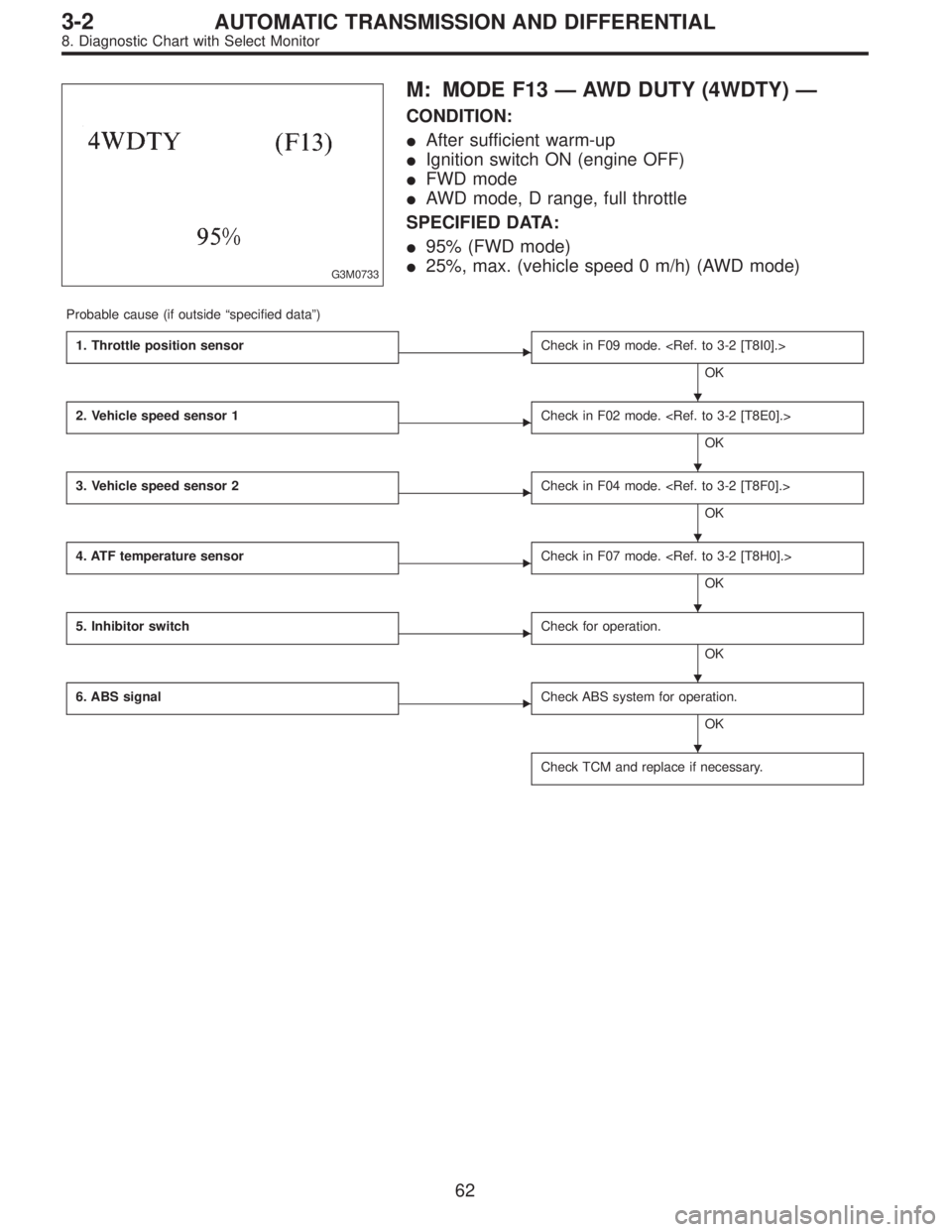
G3M0733
M: MODE F13—AWD DUTY (4WDTY)—
CONDITION:
�After sufficient warm-up
�Ignition switch ON (engine OFF)
�FWD mode
�AWD mode, D range, full throttle
SPECIFIED DATA:
�95% (FWD mode)
�25%, max. (vehicle speed 0 m/h) (AWD mode)
Probable cause (if outside“specified data”)
1. Throttle position sensor
�Check in F09 mode.
OK
2. Vehicle speed sensor 1
�Check in F02 mode.
OK
3. Vehicle speed sensor 2
�Check in F04 mode.
OK
4. ATF temperature sensor
�Check in F07 mode.
OK
5. Inhibitor switch
�Check for operation.
OK
6. ABS signal
�Check ABS system for operation.
OK
Check TCM and replace if necessary.
�
�
�
�
�
�
62
3-2AUTOMATIC TRANSMISSION AND DIFFERENTIAL
8. Diagnostic Chart with Select Monitor
Page 2203 of 2890
B3M0259
N: MODE F14
—THROTTLE POSITION SENSOR POWER
SUPPLY (THVCC)—
CONDITION:
Ignition switch ON (engine OFF)
SPECIFIED DATA:
5.12±0.1 V
Probable cause (Item outside“specified data”)
1. Throttle position sensor power supply
�Check throttle sensor line.
OK
Check TCM and replace if necessary.
B3M0370
O: MODE F15
—MASS AIR FLOW SIGNAL (AFM)—
CONDITION:
�Ignition switch ON (engine ON)
�N range
�Idling
SPECIFIED DATA:
Engine warm-up: 0.5—1.22 V
Probable cause (if outside“specified data”)
1. Mass air flow signal
�Check performance characteristics of mass air flow
signal.
OK
Check TCM and replace if necessary.
�
�
63
3-2AUTOMATIC TRANSMISSION AND DIFFERENTIAL
8. Diagnostic Chart with Select Monitor
Page 2207 of 2890

9. General Diagnostic Table
Problem parts
Inhibitor switch
Control module
Vehicle speed sensor 1
Vehicle speed sensor 2
Select cable
Select lever
FWD switch
Starter motor and harness
Throttle position sensor
Diagnosis switch
Accumulator (“N”—“D”)
Accumulator (2A)
Accumulator (4A)
Accumulator (3R)
ATF temperature sensor
Strainer
Duty solenoid A
Duty solenoid B
Shift solenoid 1
Shift solenoid 2
Shift solenoid 3
Control valve
Detent spring
Manual plate
Transfer clutch
Transfer valve
Transfer pipe
Duty solenoid C
Forward clutch
Symptom1234567891011121314151617181920212223242526272829
Starter does not rotate when select lever is
in“P”or“N.”; starter rotates when select
lever is“R”,“D”,“3”or“2.”XXXX
Abnormal noise when select lever is in“P”or
“N.”XX
Hissing noise occurs during standing starts. X
Noise occurs while driving in“D
1”range.
Noise occurs while driving in“D
2”range.
Noise occurs while driving in“D
3”range.
Noise occurs while driving in“D
4”range.
Engine stalls while shifting from one range to
another.X
Vehicle moves when select lever is in“N.”X
Shock occurs when select lever is moved
from“N”to“D.”XX X
Excessive time lag occurs when select lever
is moved from“N”to“D.”XX
Shock occurs when select lever is moved
from“N”to“R.”XXX
Excessive time lag occurs when select lever
is moved from“N”to“R.”X
Vehicle does not start in any shift range
(engine revving up).XX
Vehicle does not start in any shift range
(engine stall).
Vehicle does not start in“R”range only
(engine revving up).XX X
Vehicle does not start in“R”range only
(engine stall).X
Vehicle does not start in“D”or“3”range
(engine revving up).X
Vehicle does not start in“D”,“3”or“2”range
(engine revving up).X
Vehicle does not start in“D”,“3”or“2”range
(engine stall).
Vehicle starts in“R”range only (engine rev-
ving up).X
Acceleration during standing starts is poor
(high stall rpm).XX
Acceleration during standing starts is poor
(low stall rpm).
Acceleration is poor when select lever is in
“D”,“3”or“2”range (normal stall rpm).XX
Acceleration is poor when select lever is in
“R”(normal stall rpm).X
No shift occurs from 1st to 2nd gear. X X X X X X X
No shift occurs from 2nd to 3rd gear. XX
No shift occurs from 3rd to 4th gear. X X X X X
No“kick-down”shifts occur. X X
Engine brake is not effected when select
lever is in“3”range.XX X X
1234567891011121314151617181920212223242526272829
67
3-2AUTOMATIC TRANSMISSION AND DIFFERENTIAL
9. General Diagnostic Table
Page 2209 of 2890

Problem parts
Inhibitor switch
Control module
Vehicle speed sensor 1
Vehicle speed sensor 2
Select cable
Select lever
FWD switch
Starter motor and harness
Throttle position sensor
Diagnosis switch
Accumulator (“N”—“D”)
Accumulator (2A)
Accumulator (4A)
Accumulator (3R)
ATF temperature sensor
Strainer
Duty solenoid A
Duty solenoid B
Shift solenoid 1
Shift solenoid 2
Shift solenoid 3
Control valve
Detent spring
Manual plate
Transfer clutch
Transfer valve
Transfer pipe
Duty solenoid C
Forward clutch
Symptom1234567891011121314151617181920212223242526272829
Engine brake is not effected when select
lever is in“3”or“2”range.
Engine brake is not effected when select
lever is in“1”range.X
Shift characteristics are erroneous.XXXX X X
No lock-up occurs. X X X X
Vehicle cannot be set in“D”range power
mode.XX
“D”range power mode cannot be released. X X X
Parking brake is not effected. X X
Shift lever cannot be moved or is hard to
move from“P”range.XX
Select lever is hard to move. X X X X
Select lever is too light to move (unreason-
able resistance).XX
ATF spurts out.
Differential oil spurts out.
Differential oil level changes excessively.
Odor is produced from oil supply pipe.XX
Shock occurs when select lever is moved
from“1”to“2”range.X XXXX X
Slippage occurs when select lever is moved
from“1”to“2”range.X XXXX X
Shock occurs when select lever is moved
from“2”to“3”range.XXXXXX
Slippage occurs when select lever is moved
from“2”to“3”range.XXXXXX
Shock occurs when select lever is moved
from“3”to“4”range.X X XXX X
Slippage occurs when select lever is moved
from“3”to“4”range.X X XXX X
Shock occurs when select lever is moved
from“3”to“2”range.XXXXX
Shock occurs when select lever is moved
from“D”to“1”range.XXXXX
Shock occurs when select lever is moved
from“2”to“1”range.XXXXX
Shock occurs when accelerator pedal is
released at medium speeds.XXXXX
Vibration occurs during straight-forward
operation.XX
Select lever slips out of position during
acceleration or while driving on rough terrain.XX XX
Vibration occurs during turns (tight corner
“braking”phenomenon).XXX X X XX X
Front wheel slippage occurs during standing
starts.X X X X X X XXXX
Vehicle is not set in FWD mode. X XXX X
1234567891011121314151617181920212223242526272829
69
3-2AUTOMATIC TRANSMISSION AND DIFFERENTIAL
9. General Diagnostic Table
Page 2212 of 2890

1. Supplemental Restraint System
“Airbag”
Airbag system wiring harness is routed near the ABS/TCS
control module, ABS sensor and hydraulic control unit.
CAUTION:
�All Airbag system wiring harness and connectors
are colored yellow. Do not use electrical test equip-
ment on these circuit.
�Be careful not to damage Airbag system wiring har-
ness when servicing the ABS/TCS control module,
ABS sensor and hydraulic control unit.
2. Pre-inspection
Before performing diagnostics, check the following items
which might affect ABS/TCS problems:
A: MECHANICAL INSPECTION
1. POWER SUPPLY
1) Measure battery voltage and specific gravity of electro-
lyte.
Standard voltage: 12 V, or more
Specific gravity: Above 1.260
2) Check the condition of the main and other fuses, and
harnesses and connectors. Also check for proper ground-
ing.
2. BRAKE FLUID
1) Check brake fluid level.
2) Check brake fluid leakage.
3. BRAKE DRAG
Check brake drag.
4. BRAKE PAD AND ROTOR
Check brake pad and rotor.
5. TIRE SPECIFICATIONS, TIRE WEAR AND AIR
PRESSURE
Check tire specifications, tire wear and air pressure.
to 4-2 [S1A0].>
2
4-4bBRAKES
1. Supplemental Restraint System“Airbag”- 2. Pre-inspection
Page 2213 of 2890

1. Supplemental Restraint System
“Airbag”
Airbag system wiring harness is routed near the ABS/TCS
control module, ABS sensor and hydraulic control unit.
CAUTION:
�All Airbag system wiring harness and connectors
are colored yellow. Do not use electrical test equip-
ment on these circuit.
�Be careful not to damage Airbag system wiring har-
ness when servicing the ABS/TCS control module,
ABS sensor and hydraulic control unit.
2. Pre-inspection
Before performing diagnostics, check the following items
which might affect ABS/TCS problems:
A: MECHANICAL INSPECTION
1. POWER SUPPLY
1) Measure battery voltage and specific gravity of electro-
lyte.
Standard voltage: 12 V, or more
Specific gravity: Above 1.260
2) Check the condition of the main and other fuses, and
harnesses and connectors. Also check for proper ground-
ing.
2. BRAKE FLUID
1) Check brake fluid level.
2) Check brake fluid leakage.
3. BRAKE DRAG
Check brake drag.
4. BRAKE PAD AND ROTOR
Check brake pad and rotor.
5. TIRE SPECIFICATIONS, TIRE WEAR AND AIR
PRESSURE
Check tire specifications, tire wear and air pressure.
to 4-2 [S1A0].>
2
4-4bBRAKES
1. Supplemental Restraint System“Airbag”- 2. Pre-inspection
Page 2215 of 2890
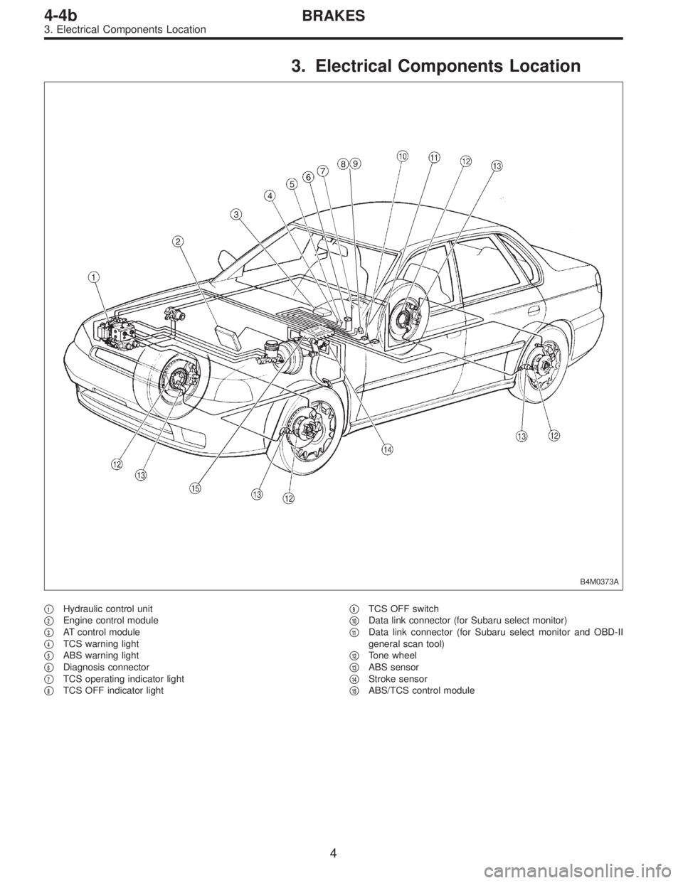
3. Electrical Components Location
B4M0373A
�1Hydraulic control unit
�
2Engine control module
�
3AT control module
�
4TCS warning light
�
5ABS warning light
�
6Diagnosis connector
�
7TCS operating indicator light
�
8TCS OFF indicator light�
9TCS OFF switch
�
10Data link connector (for Subaru select monitor)
�
11Data link connector (for Subaru select monitor and OBD-II
general scan tool)
�
12Tone wheel
�
13ABS sensor
�
14Stroke sensor
�
15ABS/TCS control module
4
4-4bBRAKES
3. Electrical Components Location
—
CONDITION:
Ignition switch ON (engine OFF)
SPECIFIED DATA:
5.12±0.1 V
Probable cause (Item outside“specified data”)
1. Thro")