Page 2130 of 2890
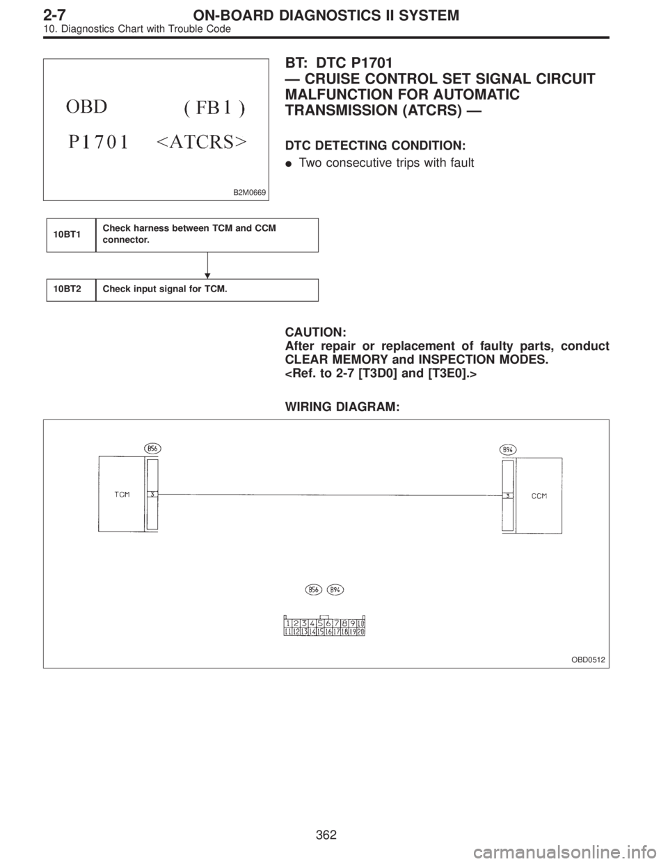
B2M0669
BT: DTC P1701
—CRUISE CONTROL SET SIGNAL CIRCUIT
MALFUNCTION FOR AUTOMATIC
TRANSMISSION (ATCRS)—
DTC DETECTING CONDITION:
�Two consecutive trips with fault
10BT1Check harness between TCM and CCM
connector.
10BT2Check input signal for TCM.
CAUTION:
After repair or replacement of faulty parts, conduct
CLEAR MEMORY and INSPECTION MODES.
WIRING DIAGRAM:
OBD0512
�
362
2-7ON-BOARD DIAGNOSTICS II SYSTEM
10. Diagnostics Chart with Trouble Code
Page 2133 of 2890
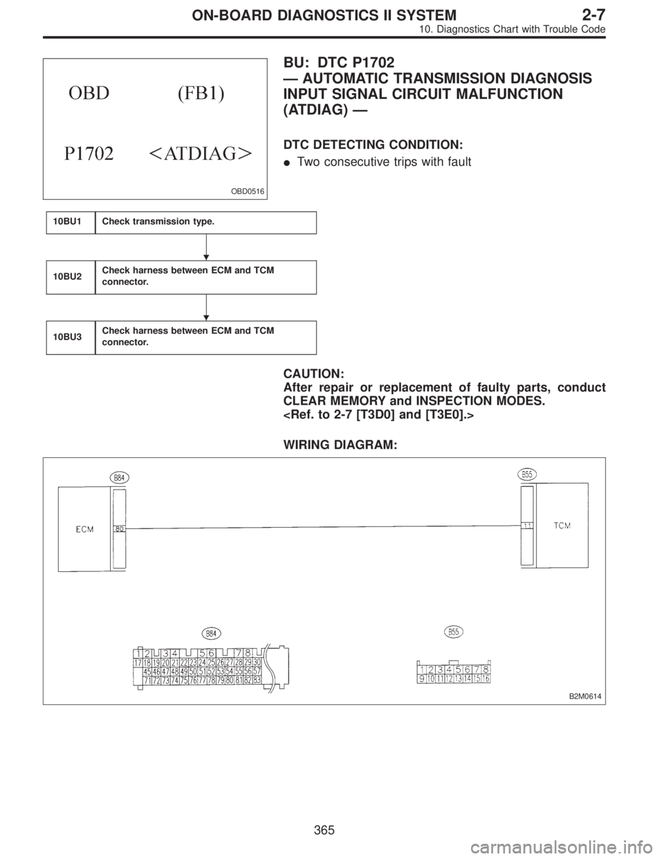
OBD0516
BU: DTC P1702
—AUTOMATIC TRANSMISSION DIAGNOSIS
INPUT SIGNAL CIRCUIT MALFUNCTION
(ATDIAG)—
DTC DETECTING CONDITION:
�Two consecutive trips with fault
10BU1Check transmission type.
10BU2Check harness between ECM and TCM
connector.
10BU3Check harness between ECM and TCM
connector.
CAUTION:
After repair or replacement of faulty parts, conduct
CLEAR MEMORY and INSPECTION MODES.
WIRING DIAGRAM:
B2M0614
�
�
365
2-7ON-BOARD DIAGNOSTICS II SYSTEM
10. Diagnostics Chart with Trouble Code
Page 2136 of 2890
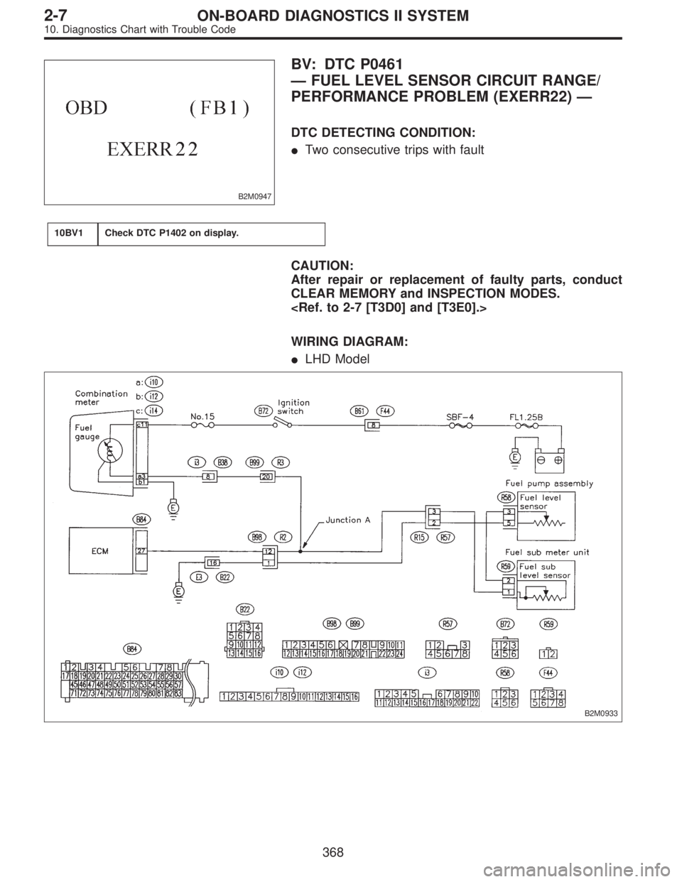
B2M0947
BV: DTC P0461
—FUEL LEVEL SENSOR CIRCUIT RANGE/
PERFORMANCE PROBLEM (EXERR22)—
DTC DETECTING CONDITION:
�Two consecutive trips with fault
10BV1Check DTC P1402 on display.
CAUTION:
After repair or replacement of faulty parts, conduct
CLEAR MEMORY and INSPECTION MODES.
WIRING DIAGRAM:
�LHD Model
B2M0933
368
2-7ON-BOARD DIAGNOSTICS II SYSTEM
10. Diagnostics Chart with Trouble Code
Page 2256 of 2890
5. CHECK SOURCES OF SIGNAL NOISE.
1) Check that the mobile phone, personal radio and other
wireless apparatus are correctly installed.
2) Check that the antenna and other possible noise
sources are distant enough from the sensor harness.
3) Check that the sealed wires of the front harness sensor
(in the engine room) are securely grounded.
4) Check that between ABS/TCS control module and the
rear sensor harness has the correct twist pitch.
Twist pitch:
25 mm (0.98 in) or less
6. CHECK HYDRAULIC UNIT OPERATIONS.
1) Operate the ABS sequence control and check that the
brake fluid pressure at the malfunctioning brake line
increases and decreases properly.
45
4-4bBRAKES
8. Diagnostics Chart with Trouble Code
Page 2305 of 2890
CodeDisplay screen
(FB0)Diagnostic items (select monitor FB1) Display screen (FB1)Ref. to
4-4b
Normal 11 NO TROUBLE Normal NO TROUBLE [T10C")
B: LIST OF TROUBLE CODE
Diagnostic items
(select monitor FB0)CodeDisplay screen
(FB0)Diagnostic items (select monitor FB1) Display screen (FB1)Ref. to
4-4b
Normal 11 NO TROUBLE Normal NO TROUBLE [T10C0]
Detection of FR sensor
hardware21 FR.SS HARDOpen circuit of FR sensor FR.SS OPEN [T10D1]
Short circuit of FR sensor FR.SS SHORT [T10D2]
Detection of FR sensor
software22 FR.SS SOFTFR sensor, variations in wheel speed FR.SS W.SPEED [T10E1]
FR sensor, reduced pressure mode FR.SS OR MV [T10E2]
FR sensor, wheel speed higher than prescribed FR.SS OVER [T10E3]
Detection of FL sensor
hardware23 FL.SS HARDOpen circuit of FL sensor FL.SS OPEN [T10F1]
Short circuit of FL sensor FL.SS SHORT [T10F2]
Detection of FL sensor
software24 FL.SS SOFTFL sensor, variations in wheel speed FL.SS W.SPEED [T10G1]
FL sensor, reduced pressure mode FL.SS OR MV [T10G2]
FL sensor, wheel speed higher than prescribed FL.SS OVER [T10G3]
Detection of RR sensor
hardware25 RR.SS HARDOpen circuit of RR sensor RR.SS OPEN [T10H1]
Short circuit of RR sensor RR.SS SHORT [T10H2]
Detection of RR sensor
software26 RR.SS SOFTRR sensor, variations in wheel speed RR.SS W.SPEED [T10I1]
RR sensor, reduced pressure mode RR.SS OR MV [T10I2]
RR sensor, wheel speed higher than prescribed RR.SS OVER [T10I3]
Detection of RL sensor
hardware27 RL.SS HARDOpen circuit of RL sensor RL.SS OPEN [T10J1]
Short circuit of RL sensor RL.SS SHORT [T10J2]
Detection of RL sensor
software28 RL.SS SOFTRL sensor, variations in wheel speed RL.SS W.SPEED [T10K1]
RL sensor, reduced pressure mode RL.SS OR MV [T10K2]
RL sensor, wheel speed higher than prescribed RL.SS OVER [T10K3]
Abnormal FR.IN valve 31 FR.IN VALVE Abnormal FR.IN valve FR.IN VALVE [T10L0]
Abnormal FR.OUT
valve32 FR.OUT VALVE Abnormal FR.OUT valve FR.OUT VALVE [T10M0]
Abnormal FL.IN valve 33 FL.IN VALVE Abnormal FL.IN valve FL.IN VALVE [T10N0]
Abnormal FL.OUT
valve34 FL.OUT VALVE Abnormal FL.OUT valve FL.OUT VALVE [T10O0]
Abnormal RR.IN valve 35 RR.IN VALVE Abnormal RR.IN valve RR.IN VALVE [T10P0]
Abnormal RR.OUT
valve36 RR.OUT VALVE Abnormal RR.OUT valve RR.OUT VALVE [T10Q0]
Abnormal RL.IN valve 37 RL.IN VALVE Abnormal RL.IN valve RL.IN VALVE [T10R0]
Abnormal RL.OUT
valve38 RL.OUT VALVE Abnormal RL.OUT valve RL.OUT VALVE [T10S0]
Abnormal ECM 41 ECU Abnormal ECM ECU [T10T0]
Abnormal line voltage 42 HIGH VOLTAGE Abnormal line voltage HIGH VOLTAGE [T10U0]
Abnormal EGI commu-
nication line43 EGI LINE Abnormal EGI communication line EGI LINE [T10V0]
Abnormal valve relay 51 V.RELAYValve relay ON failure V.RELAY ON [T10W1]
Valve relay OFF failure V.RELAY OFF [T10W2]
Abnormal motor sys-
tem52 MOTORMotor relay ON failure MOTOR ON [T10X1]
Motor relay OFF failure MOTOR OFF [T10X2]
94
4-4bBRAKES
10. Diagnostic Chart with Select Monitor
Page 2322 of 2890

B4M0518
S: TROUBLE CODE 38
RL.OUT VALVE
—Faulty rear left outlet solenoid valve—
DIAGNOSIS:
�Faulty harness/connector
�Faulty solenoid valve in hydraulic unit
�Faulty ABS/TCS control module
TROUBLE SYMPTOM:
�ABS and TCS do not operate.
�ABS sequence control does not operate.
�TCS sequence control does not operate.
�Air bleeding mode does not operate.
NOTE:
The procedures used are the same as those for FR.OUT
VA LV E .
B4M0519
T: TROUBLE CODE 41
ECU
—Faulty ABS/TCS control module—
DIAGNOSIS:
�Faulty ABS/TCS control module
�Faulty harness/connector
TROUBLE SYMPTOM:
�ABS does not operate.
�TCS does not operate.
1. Check ground circuit of ABS/TCS control
module.
OK
�Not OK
Repair harness/connector.
2. Check harness connectors between power
supply generator, battery and ABS/TCS con-
trol module.
OK
�Not OK
Repair harness/connector.
3. Check sources of signal noise.
OK
�Not OK
Repair noise sources.
Replace ABS/TCS control module.
�
�
�
111
4-4bBRAKES
10. Diagnostic Chart with Select Monitor
Page 2339 of 2890
 and,
when it operates, acceleration can become slow*. T")
12. Phenomena Peculiar to the System
1. WHEN TRAVELING WITH EXTREMELY UNDER
INFLATED TIRES
The TCS is apt to operate (particularly when turning) and,
when it operates, acceleration can become slow*. This
state is not abnormal. Immediately restore the tires to nor-
mal by traveling after releasing the TCS with the TCS OFF
switch.
* Poor acceleration is sometimes caused by the engine
itself. Check whether or not the TCS operating indicator
light (green) comes on to determine that the failure is
caused by the TCS control.
2. WHEN THE T TIRES ARE FITTED
The TCS is apt to operate (particularly when turning) and,
when it operates, acceleration can become slow. This state
is not abnormal. Immediately restore the tires to normal by
traveling after releasing the TCS with the TCS OFF switch.
3. WHEN OPERATING THE TCS CONTINUOUSLY ON
A SLOPE IMPOSSIBLE TO CLIMB OR IN STACK
S TAT E
When operating the TCS for a long time, it can be auto-
matically turned off (the OFF indicator light will come on),
stopping braking. This state is not abnormal. It automati-
cally resets by stopping and leaving the vehicle.
4. WHEN HEAVY LOAD IS PLACED ON THE BRAKES
If service brakes are used too often when descending a
long slope, heavy load can be placed on the brakes. To
prevent this problem, the TCS is automatically turned off
(the OFF indicator light will come on). This state is not
abnormal. Stop the vehicle and leave it in the same way as
step 3, it automatically resets.
5. KICKBACK TO THE BRAKE PEDAL WHEN THE
ABS IS OPERATING
Compared with ABS of the AWD model system, pedal kick-
back with large amplitude of vibration and long cycle can
be felt. This is caused by the difference in system configu-
ration and, therefore, not abnormal. If you receive an
inquiry from your clients, fully explain this point.
128
4-4bBRAKES
12. Phenomena Peculiar to the System
Page 2340 of 2890

6. INSPECTOR
Before advancing the vehicle after the engine starts, drive
the pump motor and valve for a very short time to function-
ally check the ABS/TCS brakes. It is not abnormal if, at this
time, operating noises of the valve and motor are produced
or kickback of the brake pedal is felt when stepping on the
pedal.
7. WHEN ATTACHING CHAINS
It is sometimes a good idea to turn off the TCS for better
advancing and accelerating the vehicle.
8. WHEN A DRUM TESTER IS USED (SPEEDOMETER
TEST, EXHAUST GAS TEST, BRAKE TEST, ETC.)
Before performing tests, turn the TCS off by operating the
TCS OFF switch or disconnect the fuse of ECM input
power source to put the machine out of operation. If oper-
ating other parts to put the TCS in the fail state
intentionally, trouble code will be recorded. Make sure to
clear the memory. Also, in a 2-wheel tester, wheel speed
sensor failure can be detected, making the TCS fail. This
case is also not abnormal and clearing the memory is
required.
129
4-4bBRAKES
12. Phenomena Peculiar to the System
 Check that the mobile phone, personal radio and other
wireless apparatus are correctly installed.
2) Check that the antenna and other possible noise
sources are di")