Page 2099 of 2890
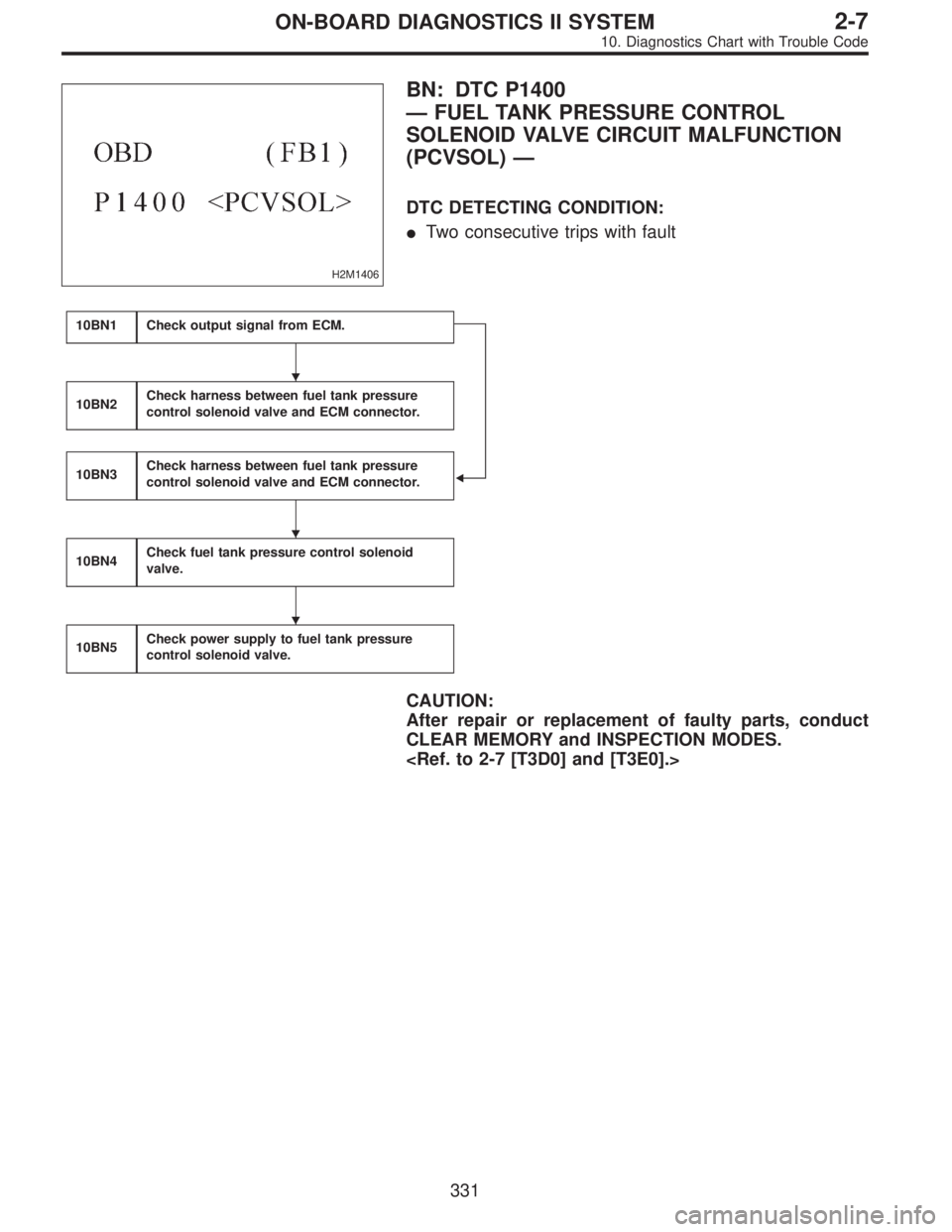
H2M1406
BN: DTC P1400
—FUEL TANK PRESSURE CONTROL
SOLENOID VALVE CIRCUIT MALFUNCTION
(PCVSOL)—
DTC DETECTING CONDITION:
�Two consecutive trips with fault
10BN1Check output signal from ECM.
�
10BN2Check harness between fuel tank pressure
control solenoid valve and ECM connector.
10BN3Check harness between fuel tank pressure
control solenoid valve and ECM connector.
10BN4Check fuel tank pressure control solenoid
valve.
10BN5Check power supply to fuel tank pressure
control solenoid valve.
CAUTION:
After repair or replacement of faulty parts, conduct
CLEAR MEMORY and INSPECTION MODES.
�
�
�
331
2-7ON-BOARD DIAGNOSTICS II SYSTEM
10. Diagnostics Chart with Trouble Code
Page 2105 of 2890
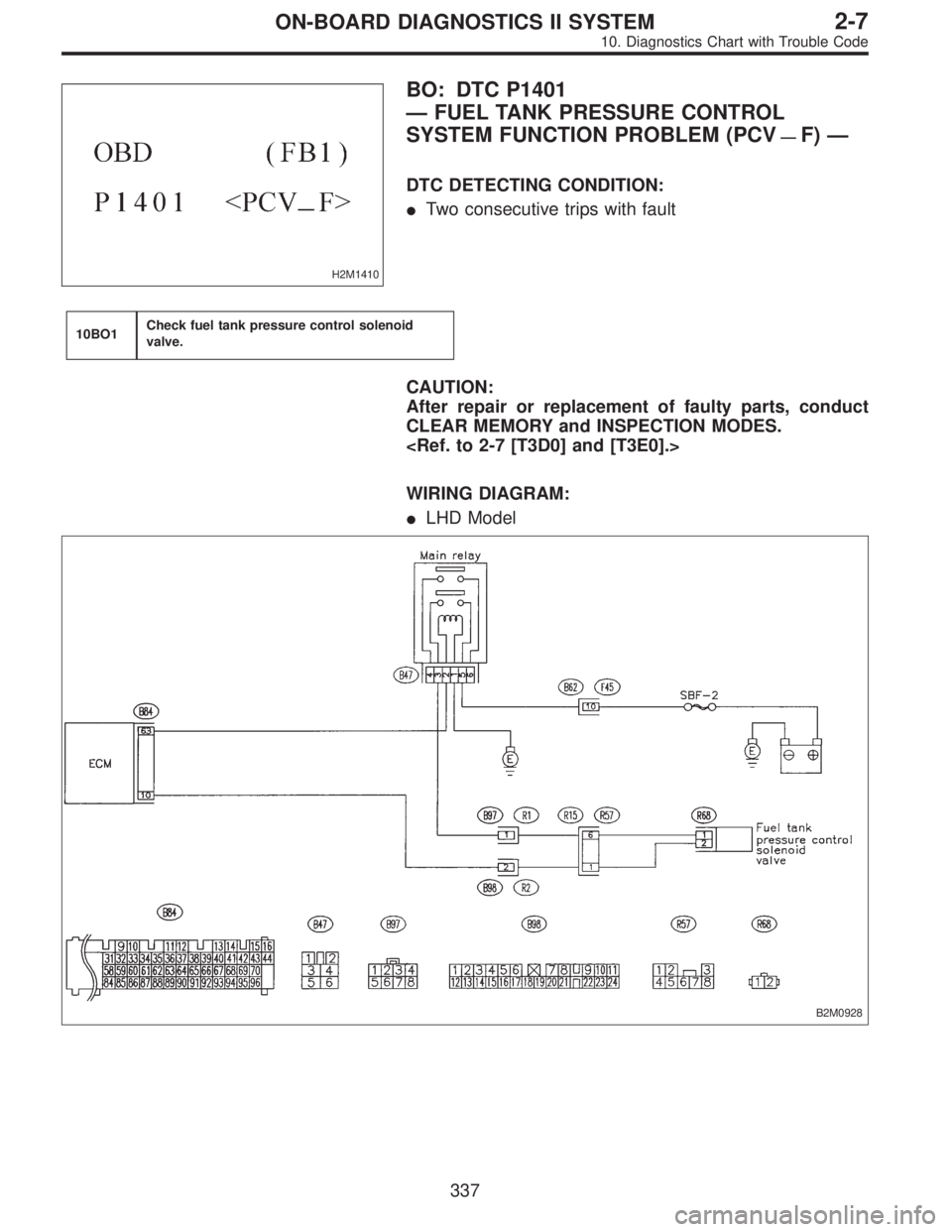
H2M1410
BO: DTC P1401
—FUEL TANK PRESSURE CONTROL
SYSTEM FUNCTION PROBLEM (PCV
—F)—
DTC DETECTING CONDITION:
�Two consecutive trips with fault
10BO1Check fuel tank pressure control solenoid
valve.
CAUTION:
After repair or replacement of faulty parts, conduct
CLEAR MEMORY and INSPECTION MODES.
WIRING DIAGRAM:
�LHD Model
B2M0928
337
2-7ON-BOARD DIAGNOSTICS II SYSTEM
10. Diagnostics Chart with Trouble Code
Page 2106 of 2890
WIRING DIAGRAM:
�RHD Model
B2M1020
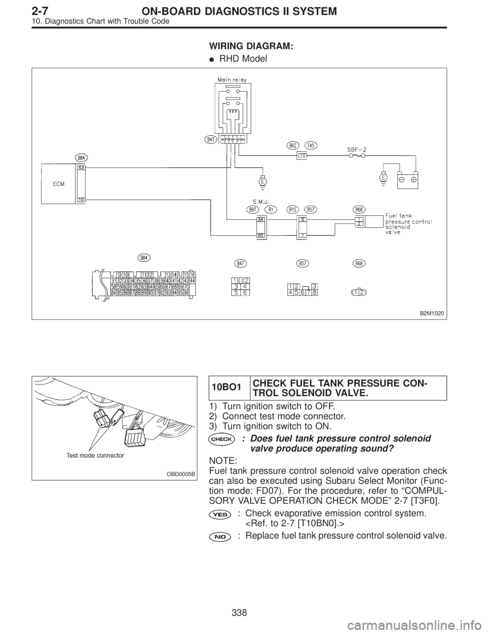
OBD0005B
10BO1CHECK FUEL TANK PRESSURE CON-
TROL SOLENOID VALVE.
1) Turn ignition switch to OFF.
2) Connect test mode connector.
3) Turn ignition switch to ON.
: Does fuel tank pressure control solenoid
valve produce operating sound?
NOTE:
Fuel tank pressure control solenoid valve operation check
can also be executed using Subaru Select Monitor (Func-
tion mode: FD07). For the procedure, refer to“COMPUL-
SORY VALVE OPERATION CHECK MODE”2-7 [T3F0].
: Check evaporative emission control system.
: Replace fuel tank pressure control solenoid valve.
338
2-7ON-BOARD DIAGNOSTICS II SYSTEM
10. Diagnostics Chart with Trouble Code
Page 2107 of 2890
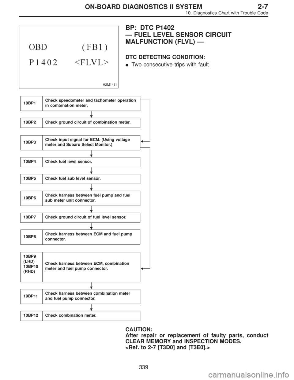
H2M1411
BP: DTC P1402
—FUEL LEVEL SENSOR CIRCUIT
MALFUNCTION (FLVL)—
DTC DETECTING CONDITION:
�Two consecutive trips with fault
10BP1Check speedometer and tachometer operation
in combination meter.
�
�
10BP2Check ground circuit of combination meter.
10BP3Check input signal for ECM. (Using voltage
meter and Subaru Select Monitor.)
10BP4Check fuel level sensor.
10BP5Check fuel sub level sensor.
10BP6Check harness between fuel pump and fuel
sub meter unit connector.
10BP7Check ground circuit of fuel level sensor.
10BP8Check harness between ECM and fuel pump
connector.
10BP9
(LHD)
10BP10
(RHD)
Check harness between ECM, combination
meter and fuel pump connector.
10BP11Check harness between combination meter
and fuel pump connector.
10BP12Check combination meter.
CAUTION:
After repair or replacement of faulty parts, conduct
CLEAR MEMORY and INSPECTION MODES.
�
�
�
�
�
�
�
�
339
2-7ON-BOARD DIAGNOSTICS II SYSTEM
10. Diagnostics Chart with Trouble Code
Page 2118 of 2890
![SUBARU LEGACY 1996 Service Repair Manual B6M0121
10BP11CHECK HARNESS BETWEEN COMBINA-
TION METER AND FUEL PUMP CONNEC-
TOR.
1) Connect connector to fuel pump.
2) Pull out combination meter from instrument panel. <Ref.
to 6-2 [W13A1].>
3) Dis](/manual-img/17/57433/w960_57433-2117.png "SUBARU LEGACY 1996 Service Repair Manual B6M0121
10BP11CHECK HARNESS BETWEEN COMBINA-
TION METER AND FUEL PUMP CONNEC-
TOR.
1) Connect connector to fuel pump.
2) Pull out combination meter from instrument panel. <Ref.
to 6-2 [W13A1].>
3) Dis")
B6M0121
10BP11CHECK HARNESS BETWEEN COMBINA-
TION METER AND FUEL PUMP CONNEC-
TOR.
1) Connect connector to fuel pump.
2) Pull out combination meter from instrument panel.
to 6-2 [W13A1].>
3) Disconnect connector from combination meter.
B2M0945A
4) Measure resistance of harness between combination
meter connector and chassis ground.
: Connector & terminal
(i10) No. 3—Chassis ground:
Is the resistance less than 200Ω?
: Go to step10BP12.
: Repair harness and connector.
NOTE:
In this case, repair the following:
�Open circuit in harness between combination meter con-
nector and junction A on rear wiring harness
�Poor contact in coupling connectors (i3, and B99 (LHD)/
B97 (RHD))
10BP12
CHECK COMBINATION METER.
1) Disconnect speedometer cable from combination meter
and remove combination meter.
: Is the fuel meter installation screw tightened
securely?
: Go to next step 2).
: Tighten fuel meter installation screw securely.
2) Remove printed circuit plate assembly from combina-
tion meter assembly.
: Is there flaw or burning on printed circuit
plate assembly?
: Replace printed circuit plate assembly.
: Replace fuel meter assembly.
350
2-7ON-BOARD DIAGNOSTICS II SYSTEM
10. Diagnostics Chart with Trouble Code
Page 2119 of 2890
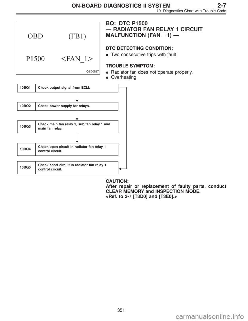
OBD0527
BQ: DTC P1500
—RADIATOR FAN RELAY 1 CIRCUIT
MALFUNCTION (FAN
—1)—
DTC DETECTING CONDITION:
�Two consecutive trips with fault
TROUBLE SYMPTOM:
�Radiator fan does not operate properly.
�Overheating
10BQ1Check output signal from ECM.
�
10BQ2Check power supply for relays.
10BQ3Check main fan relay 1, sub fan relay 1 and
main fan relay.
10BQ4Check open circuit in radiator fan relay 1
control circuit.
10BQ5Check short circuit in radiator fan relay 1
control circuit.
CAUTION:
After repair or replacement of faulty parts, conduct
CLEAR MEMORY and INSPECTION MODE.
�
�
�
351
2-7ON-BOARD DIAGNOSTICS II SYSTEM
10. Diagnostics Chart with Trouble Code
Page 2126 of 2890
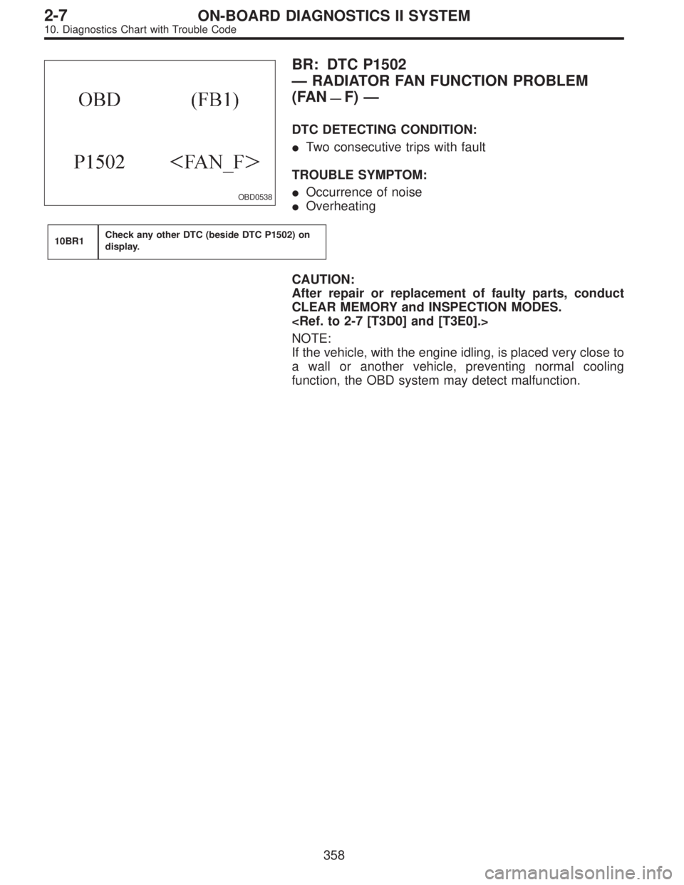
OBD0538
BR: DTC P1502
—RADIATOR FAN FUNCTION PROBLEM
(FAN
—F)—
DTC DETECTING CONDITION:
�Two consecutive trips with fault
TROUBLE SYMPTOM:
�Occurrence of noise
�Overheating
10BR1Check any other DTC (beside DTC P1502) on
display.
CAUTION:
After repair or replacement of faulty parts, conduct
CLEAR MEMORY and INSPECTION MODES.
NOTE:
If the vehicle, with the engine idling, is placed very close to
a wall or another vehicle, preventing normal cooling
function, the OBD system may detect malfunction.
358
2-7ON-BOARD DIAGNOSTICS II SYSTEM
10. Diagnostics Chart with Trouble Code
Page 2129 of 2890
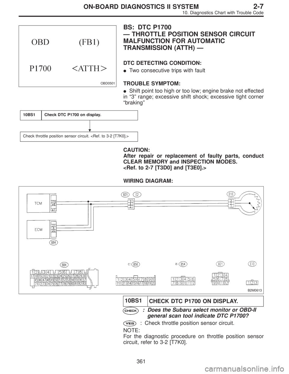
OBD0501
BS: DTC P1700
—THROTTLE POSITION SENSOR CIRCUIT
MALFUNCTION FOR AUTOMATIC
TRANSMISSION (ATTH)—
DTC DETECTING CONDITION:
�Two consecutive trips with fault
TROUBLE SYMPTOM:
�Shift point too high or too low; engine brake not effected
in“3”range; excessive shift shock; excessive tight corner
“braking”
10BS1Check DTC P1700 on display.
Check throttle position sensor circuit.
CAUTION:
After repair or replacement of faulty parts, conduct
CLEAR MEMORY and INSPECTION MODES.
WIRING DIAGRAM:
B2M0613
10BS1
CHECK DTC P1700 ON DISPLAY.
: Does the Subaru select monitor or OBD-II
general scan tool indicate DTC P1700?
: Check throttle position sensor circuit.
NOTE:
For the diagnostic procedure on throttle position sensor
circuit, refer to 3-2 [T7K0].
�
361
2-7ON-BOARD DIAGNOSTICS II SYSTEM
10. Diagnostics Chart with Trouble Code