Page 2487 of 2890

Are the ABS sensor installation bolts tight-
ened securely?
: Go to next.
: Tighten ABS sensor i")
10L6CHECK ABS SENSOR MECHANICAL
TROUBLE.
: Tightening torque:
32±10 N⋅m (3.3±1.0 kg-m, 24±7 ft-lb)
Are the ABS sensor installation bolts tight-
ened securely?
: Go to next.
: Tighten ABS sensor installation bolts securely.
: Tightening torque:
13±3 N⋅m (1.3±0.3 kg-m, 9±2.2 ft-lb)
Are the tone wheel installation bolts tight-
ened securely?
: Go to next step.
: Tighten tone wheel installation bolts securely.
G4M0700
1) Measure tone wheel to pole piece gap over entire
perimeter of the wheel.
: Is the gap within the specifications shown
in the following table?
SpecificationsFront wheel Rear wheel
0.9—1.4 mm
(0.035—0.055 in)0.7—1.2 mm
(0.028—0.047 in)
G4M0701
: Go to next.
: Adjust the gap.
NOTE:
Adjust the gap using spacer (Part No. 26755AA000). If
spacers cannot correct the gap, replace worn sensor or
worn tone wheel.
: Is an oscilloscope available?
: Go to next step.
: Go to step 10).
2) Raise all four wheels of ground.
3) Turn ignition switch OFF.
4) Disconnect connector from ABS control module.
5) Disconnect connector cover from connector.
6) Connect connector to ABS control module.
7) Connect the oscilloscope to the ABS control module
connector in accordance with trouble code.
8) Turn ignition switch ON.
147
4-4cBRAKES [ABS 5.3 TYPE]
10. Diagnostics Chart with Select Monitor
Page 2495 of 2890
10M2
CHECK TIRE.
: Are the tire specifications correct?
: Go to next.
: Replace tire.
: Is the tire worn excessively?
: Replace tire.
: Go to next.
: Is the tire pressure correct?
: Go to step10M3.
: Adjust tire pressure.
10M3CHECK ABS SENSOR MECHANICAL
TROUBLE.
: Tightening torque:
32±10 N⋅m (3.3±1.0 kg-m, 24±7 ft-lb)
Are the ABS sensor installation bolts tight-
ened securely?
: Go to next.
: Tighten ABS sensor installation bolts securely.
: Tightening torque:
13±3 N⋅m (1.3±0.3 kg-m, 9±2.2 ft-lb)
Are the ABS sensor installation bolts tight-
ened securely?
: Go to next step.
: Tighten ABS sensor installation bolts securely.
G4M0700
1) Measure tone wheel to pole piece gap over entire
perimeter of the wheel.
: Is the gap within the specifications shown
in the following table?
SpecificationsFront wheel Rear wheel
0.9—1.4 mm
(0.035—0.055 in)0.7—1.2 mm
(0.028—0.047 in)
155
4-4cBRAKES [ABS 5.3 TYPE]
10. Diagnostics Chart with Select Monitor
Page 2522 of 2890
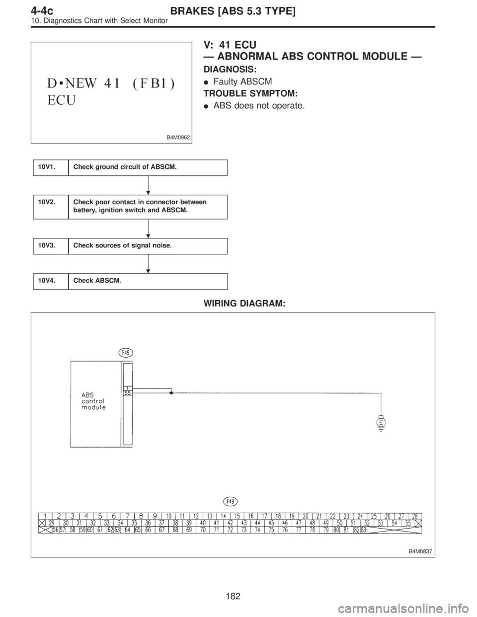
B4M0962
V: 41 ECU
—ABNORMAL ABS CONTROL MODULE—
DIAGNOSIS:
�Faulty ABSCM
TROUBLE SYMPTOM:
�ABS does not operate.
10V1.Check ground circuit of ABSCM.
10V2.Check poor contact in connector between
battery, ignition switch and ABSCM.
10V3.Check sources of signal noise.
10V4.Check ABSCM.
WIRING DIAGRAM:
B4M0837
�
�
�
182
4-4cBRAKES [ABS 5.3 TYPE]
10. Diagnostics Chart with Select Monitor
Page 2626 of 2890
![SUBARU LEGACY 1996 Service Repair Manual 24) Turn ignition switch“OFF”, disconnect battery ground cable,
and wait 20 seconds. Remove driver side airbag module and
connect test harness C connector (1C) to (AB7) <Ref. to 5-5
[W3A1].> with](/manual-img/17/57433/w960_57433-2625.png "SUBARU LEGACY 1996 Service Repair Manual 24) Turn ignition switch“OFF”, disconnect battery ground cable,
and wait 20 seconds. Remove driver side airbag module and
connect test harness C connector (1C) to (AB7) <Ref. to 5-5
[W3A1].> with")
24) Turn ignition switch“OFF”, disconnect battery ground cable,
and wait 20 seconds. Remove driver side airbag module and
connect test harness C connector (1C) to (AB7)
[W3A1].> with airbag resistor attached to test harness C con-
nector (3C).
G5M0430
25) Reconnect battery ground cable and turn ignition switch“ON”. Does airbag warning light go“OFF”after 8 seconds and remain off
for more than 30 seconds? See notes 1) and 2). (Refer to end of chart.) If“YES”, proceed to step 26). If“NO”, proceed to step
27).
26) Turn ignition switch“OFF”, disconnect battery ground cable, and wait 20 seconds. Install driver side airbag module
[W3B0].> and proceed to step 27).
27) Replace combination switch, and proceed to step 26).
28) Reconnect battery and turn ignition switch“ON”. Does airbag warning light go off after 8 seconds and remain off for more than 30
seconds? See notes 1) and 2). (Refer to end of chart.) If“YES”, proceed to step 29). If“NO”, proceed to step 31).
29) Perform clear memory procedure.
30) If memory cannot be cleared, another trouble code exists. Return to step 1).
31) Turn ignition switch“OFF”, disconnect battery ground cable, and wait 20 seconds. Replace driver side airbag module.
5-5 [W3A1].> Proceed to step 28).
NOTES:
1) Always remember to secure the green double locks before turning the ignition switch “ON”.
2) In some cases the airbag warning light will go “OFF” after 8 seconds but will turn “ON” again within 30 seconds. In this
case continue diagnostics with the basic diagnostics procedures or trouble code procedures.
14
5-5SUPPLEMENTAL RESTRAINT SYSTEM
4. Diagnostics Chart for On-board Diagnostic System
Page 2669 of 2890
![SUBARU LEGACY 1996 Service Repair Manual G5M0589
11) Turn ignition switch“OFF”, disconnect battery ground
cable, and wait 20 seconds. Disconnect passenger side
airbag module connector (AB9) to (AB10). <Ref. to 5-5b
[W3A2].>
Connect test](/manual-img/17/57433/w960_57433-2668.png "SUBARU LEGACY 1996 Service Repair Manual G5M0589
11) Turn ignition switch“OFF”, disconnect battery ground
cable, and wait 20 seconds. Disconnect passenger side
airbag module connector (AB9) to (AB10). <Ref. to 5-5b
[W3A2].>
Connect test")
G5M0589
11) Turn ignition switch“OFF”, disconnect battery ground
cable, and wait 20 seconds. Disconnect passenger side
airbag module connector (AB9) to (AB10).
[W3A2].>
Connect test harness C connector (1C) to (AB9). Connect
airbag resistor to test harness C connector (3C).
Connect battery ground cable and turn ignition switch
“ON”. Does airbag warning light go“OFF”after 8 seconds
and remain off for more than 30 seconds?
See“NOTE:”.
If“YES”proceed to step 12).
If“NO”proceed to step 3).
12) Turn ignition switch“OFF”, disconnect battery ground
cable, and wait 20 seconds. Replace with a new passen-
ger side airbag module then pro-
ceed to step 15).
13) Turn ignition switch“OFF”, disconnect battery ground
cable and wait 20 seconds. Replace with a new passenger
side airbag module then proceed
to step 7).
14) Turn ignition switch“OFF”, disconnect battery ground
cable, and wait 20 seconds. Replace with a new combina-
tion switch, and install driver side
airbag module .
Connect battery ground cable and turn ignition switch
“ON”. Does airbag warning light go“OFF”after 8 seconds
and remain off for more than 30 seconds?
See“NOTE:”.
If“YES”proceed to step 16).
If“NO”proceed to step 9).
15) Connect battery ground cable and turn ignition switch
“ON”. Does airbag warning light go“OFF”after 8 seconds
and remain off for more than 30 seconds? See“NOTE:”.
If“YES”proceed to step 16).
If“NO”proceed to step 1).
16) Perform clear memory procedure.
[T4C0].>
If memory cannot be cleared, another trouble code exists.
Return to step 1).
If memory can be cleared, proceed to step 17).
17) END
NOTE:
�Always remember to secure the green double locks
before turning the ignition switch“ON”.
�In some cases the airbag warning light will go“OFF”
after 8 seconds but will turn“ON”again within 30 seconds.
In this case continue diagnostics with the basic diagnostics
procedures or trouble code procedures.
15
5-5bSUPPLEMENTAL RESTRAINT SYSTEM (ELECTRIC SENSOR TYPE)
4. Diagnostics Chart for On-board Diagnostic System
Page 2717 of 2890
BR
5 Inhibitor switch (AT) N
6——
7——
8——
9——
10—�")
LED No. Signal name Display
1 SET/COAST switch SE
2 RESUME/ACCEL switch RE
3 Stop light switch ST
4�Brake switch
�Clutch switch (MT)BR
5 Inhibitor switch (AT) N
6——
7——
8——
9——
10——
SE RE ST BR N
—————
1
2345
678910
1. CHECK THE SIGNAL USING A SELECT MONITOR.
1) Turn ignition switch to ON.
2) Turn cruise control main switch to ON.
3) Apply parking brake securely.
4) Set select monitor in“FA 0”mode.
5) Release the clutch pedal. (MT model)
6) Depress the brake pedal and check signals for proper
operation.
Stop light switch: LED No. 3 goes out—lights.
Brake switch : LED No. 4 goes out—lights.
7) Release the brake pedal.
8) Depress the clutch pedal and check signal for proper
operation. (MT model)
Clutch switch: LED No. 4 goes out—lights.
9) Set the selector lever from D to N position and check
signal for proper operation. (AT model)
Inhibitor switch: LED No. 5 goes out—lights.
G6M0183
2. CHECK BRAKE SWITCH AND STOP LIGHT
SWITCH.
1) Remove connector of stop and brake switch.
2) Check circuit between each terminal.
Pedal operationBrake switch between
No. 1—No. 4Stop light switch between
No. 2—No. 3
Depressing the
brake pedal.1MΩ,ormore 1Ω, or less
Without
depressing the
brake pedal.1Ω, or less 1 MΩ,ormore
G6M0184
3. CHECK CLUTCH SWITCH. (MT MODEL)
1) Disconnect connector from clutch switch.
2) Check continuity of the clutch switch.
Terminals / Specified resistance:
No. 1—No. 2 / 10Ω, max. (Without pedal
depressing.)
/1MΩ, min. (Pedal depressing.)
20
6-2BODY ELECTRICAL SYSTEM
8. Diagnostics Chart with Trouble Code
Page 2735 of 2890
 The table below lists the nominal sectional areas and
allowable currents of the wires.
Nominal
sectional area
mm
2
No. of strands/
strand diameterOutside
diameter of
finished wiring
mmAllowable
cur")
8) The table below lists the nominal sectional areas and
allowable currents of the wires.
Nominal
sectional area
mm
2
No. of strands/
strand diameterOutside
diameter of
finished wiring
mmAllowable
current
Amps/40°C
0.3 7/0.26 1.8 7
0.5 7/0.32 2.2 (or 2.0) 12
0.75 30/0.18 2.6 (or 2.4) 16
0.85 11/0.32 2.4 (or 2.2) 16
1.25 16/0.32 2.7 (or 2.5) 21
2 26/0.32 3.1 (or 2.9) 28
3 41/0.32 3.8 (or 3.6) 38
5 65/0.32 4.6 (or 4.4) 51
8 50/0.45 5.5 67
CAUTION:
When replacing or repairing a wire, be sure to use the
same size and type of the wire which was originally
used.
NOTE:
�The allowable current in the above table indicates the
tolerable amperage of each wire at an ambient tempera-
ture of 40°C (104°F).
�The allowable current changes with ambient tempera-
ture. Also, it changes if a bundle of more than two wires is
used.
G6M0203
9) Each unit is directly grounded to the body or indirectly
grounds through a harness ground terminal. Different sym-
bols are used in the wiring diagram to identify the two
grounding systems.
The ground points shown in the wiring diagram refer to the
following:
�GBBody ground
�GEEngine ground
�GRRadio ground
�GDRear defogger ground
All wiring harnesses are provided with a ground point which
should be securely connected.
5
6-3WIRING DIAGRAM
1. General Description
Page 2741 of 2890
 When working under a vehicle which is jacked-up,
always be sure to use safety stands.
2) The parking brake m")
3. Working Precautions
1. PRECAUTIONS WHEN WORKING WITH THE
PARTS MOUNTED ON THE VEHICLE
1) When working under a vehicle which is jacked-up,
always be sure to use safety stands.
2) The parking brake must always be applied during work-
ing. Also, in automatic transmission vehicles, keep the
select lever set to the P (Parking) range.
3) Be sure the workshop is properly ventilated when run-
ning the engine. Further, be careful not to touch the belt or
fan while the engine is operating.
4) Be careful not to touch hot metal parts, especially the
radiator and exhaust system immediately after the engine
has been shut off.
2. PRECAUTIONS IN TROUBLE DIAGNOSIS AND
REPAIR OF ELECTRIC PARTS
1) The battery cable must be disconnected from the bat-
tery’s (�) terminal, and the ignition switch must be set to the
OFF position, unless otherwise required by the diagnos-
tics.
2) Securely fasten the wiring harness with clamps and
slips so that the harness does not interfere with the body
end parts or edges and bolts or screws.
3) When installing parts, be careful not to catch them on
the wiring harness.
G6M0212
4) When disconnecting a connector, do not pull the wires,
but pull while holding the connector body.
11
6-3WIRING DIAGRAM
3. Working Precautions