Page 366 of 2890
C: INSPECTION
1. CYLINDER BLOCK
1) Check for cracks and damage visually. Especially,
inspect important parts by means of red lead check.
2) Check the oil passages for clogging.
3) Inspect crankcase surface that mates with cylinder
head for warping by using a straight edge, and correct by
grinding if necessary.
Warping limit:
0.05 mm (0.0020 in)
Grinding limit:
0.1 mm (0.004 in)
Standard height of cylinder block:
201.0 mm (7.91 in)
B2M0082A
2. CYLINDER AND PISTON
1) The cylinder bore size is stamped on the cylinder
block’s front upper surface.
NOTE:
Standard sized pistons are classified into two grades,“A”
and“B”. These grades should be used as a guide line in
selecting a standard piston.
Standard diameter:
A: 96.905—96.915 mm (3.8151—3.8155 in)
B: 96.895—96.905 mm (3.8148—3.8151 in)
56
2-3SERVICE PROCEDURE
7. Cylinder Block
Page 384 of 2890
B2M0390A
(2) Apply fluid packing to matching surface of oil pump.
Fluid packing:
THREE BOND 1215 or equivalent
(3) Install oil pump on cylinder block. Be careful not to
damage oil seal during installation.
CAUTION:
�Do not forget to install O-ring and seal when install-
ing oil pump.
�Align flat surface of oil pump’s inner rotor with
crankshaft before installation.
G2M0628
9) Install engine coolant pump and gasket.
CAUTION:
�Be sure to use a new gasket.
�When installing engine coolant pump, tighten bolts
in two stages in numerical sequence as shown in Fig-
ure.
10) Install engine coolant pipe.
11) Install oil filter.
2. RELATED PARTS
1) Install cylinder head and intake manifold.
2) Install timing belt, camshaft sprocket and related parts.
74
2-3SERVICE PROCEDURE
7. Cylinder Block
Page 386 of 2890

After burning in exhaust system
Knock")
TROUBLE
Engine will not start.
Rough idle and engine stall
Low output, hesitation and poor acceleration
Surging
Engine does not return to idle.
Dieseling (Run-on)
After burning in exhaust system
Knocking
Excessive engine oil consumption
Excessive fuel consumption Starter does not turn.
Initial combustion does not occur.
Initial combustion occurs.
Engine stalls after initial combustion.
INTAKE SYSTEM
2111 3�Loosened or cracked intake air pipe
3111 3 1�Loosened or cracked blow-by hose
31211 2�Loosened or cracked vacuum hose
22222�Defective intake manifold gasket
22222�Defective throttle body gasket
322 2 2�Defective PCV valve
222 323�Loosened oil filler cap
3312 1�Dirty air cleaner element
FUEL LINE
13 322�Defective fuel pump and relay
33322�Clogged fuel line
222233�Lack of or insufficient fuel
BELT
222�Defective
222322 22 2�Defective timing
FRICTION
3�Seizure of crankshaft and connecting rod bearing
3�Seized camshaft
3�Seized or stuck piston and cylinder
COMPRESSION
333222 23 2�Defective hydraulic lash adjuster
333223 3 3�Loosened spark plugs or defective gasket
333223 3 3�Loosened cylinder head bolts or defective gasket
333223 2 2�Improper valve seating
333333 3 13�Defective valve stem
222223 3 3�Worn or broken valve spring
333233 3 12�Worn or stuck piston rings, cylinder and piston
222111 12 2�Incorrect valve timing
222222�Improper engine oil (low viscosity)
76
2-3DIAGNOSTICS
1. Engine Trouble in General
Page 390 of 2890
1. Engine
A: SPECIFICATIONS
EngineModel2500 cc
TypeHorizontally opposed, liquid cooled, 4-cylinder, 4-stroke
gasoline engine
Valve arrangement Belt driven, double over-head camshaft, 4-valve/cylinder
Bore x Stroke mm (in) 99.5 x 79.0 (3.917 x 3.110)
Displacement cm
3(cu in) 2,457 (149.93)
Compression ratio9.5
Compression pressure
(at 200 — 300 rpm)
kPa (kg/cm
2, psi) � rpmStandard 1,216 (12.4, 176) � 350
Limit 941 (9.6, 137) � 350
Number of piston rings Pressure ring: 2, Oil ring: 1
Intake valve timingOpening 6° BTDC
Closing 50° ABDC
Exhaust valve timingOpening 62° BBDC
Closing 10° ATDC
Idling speed
[At neutral position on MT, or
“P” or “N” position on AT] rpm700±100 (No load)
850±50 (A/C switch ON)
Firing order1,3,2,4
Ignition timing BTDC/rpm 15°±8°/700 rpm
2
2-3bSPECIFICATIONS AND SERVICE DATA
1. Engine
Page 391 of 2890

Belt ten-
sionerSpacer O.D. 16 mm (0.63 in)
Tensioner bush I.D. 16.16 mm (0.6362 in)
Clearance between")
B: SERVICE DATA
Belt
tension
adjusterProtrusion of adjuster rod 15.4—16.4 mm (0.606—0.646 in)
Belt ten-
sionerSpacer O.D. 16 mm (0.63 in)
Tensioner bush I.D. 16.16 mm (0.6362 in)
Clearance between spacer and bushSTD 0.117—0.180 mm (0.0046—0.0071 in)
Limit 0.230 mm (0.0091 in)
Side clearance of spacerSTD 0.37—0.54 mm (0.0146—0.0213 in)
Limit 0.8 mm (0.031 in)
CamshaftBend limit 0.020 mm (0.0008 in)
Thrust clearanceSTD 0.040—0.080 mm (0.0016—0.0031 in)
Limit 0.10 mm (0.0039 in)
Cam lobe heightIntakeSTD 41.68—41.78 mm (1.6409—1.6449 in)
Limit 41.52 mm (1.6346 in)
ExhaustSTD 41.98—42.08 mm (1.6528—1.6567 in)
Limit 41.82 mm (1.6465 in)
Camshaft journal O.D.Front 31.946—31.963 mm (1.2577—1.2584 in)
Center 27.946—27.963 mm (1.1002—1.1009 in)
Rear 27.946—27.963 mm (1.1002—1.1009 in)
Camshaft journal hole I.D.Front 32.000—32.018 mm (1.2598—1.2605 in)
Center 28.000—28.018 mm (1.1024—1.1031 in)
Rear 28.000—28.018 mm (1.1024—1.1031 in)
Oil clearanceSTD 0.037—0.072 mm (0.0015—0.0028 in)
Limit 0.10 mm (0.0039 in)
Cylinder
headSurface warpage limit 0.05 mm (0.0020 in)
Surface grinding limit 0.3 mm (0.012 in)
Standard height 127.5 mm (5.02 in)
Valve seatRefacing angle 90°
Contacting widthIntakeSTD 1.0 mm (0.039 in)
Limit 1.7 mm (0.067 in)
ExhaustSTD 1.5 mm (0.059 in)
Limit 2.2 mm (0.087 in)
Valve
guideInner diameter 6.000—6.015 mm (0.2362—0.2368 in)
Protrusion above head 12.0—12.4 mm (0.472—0.488 in)
ValveHead edge thicknessIntakeSTD 1.2 mm (0.047 in)
Limit 0.8 mm (0.031 in)
ExhaustSTD 1.5 mm (0.059 in)
Limit 0.8 mm (0.031 in)
Stem diameterIntake 5.950—5.965 mm (0.2343—0.2348 in)
Exhaust 5.950—5.965 mm (0.2343—0.2348 in)
Stem oil clearanceSTDIntake 0.035—0.062 mm (0.0014—0.0024 in)
Exhaust 0.040—0.067 mm (0.0016—0.0026 in)
Limit—0.15 mm (0.0059 in)
Overall lengthIntake 93.3 mm (3.673 in)
Exhaust 93.6 mm (3.685 in)
STD: Standard I.D.: Inner Diameter O.D.: Outer Diameter
3
2-3bSPECIFICATIONS AND SERVICE DATA
1. Engine
Page 392 of 2890

Squareness 2.5°, 1.7 mm (0.067 in)
Tension/spring height228.5—261.8 N
(23.3—26.7 kg, 51.4—58.9 lb)/31.0 mm (1.220 in)
462.9—531.5 N
(47.2—54.2 kg,")
Valve springFree length 39.8 mm (1.567 in)
Squareness 2.5°, 1.7 mm (0.067 in)
Tension/spring height228.5—261.8 N
(23.3—26.7 kg, 51.4—58.9 lb)/31.0 mm (1.220 in)
462.9—531.5 N
(47.2—54.2 kg, 104.1—119.5 lb)/23.2 mm (0.913 in)
Cylinder
blockSurface warpage limit (mating with cylinder head) 0.05 mm (0.0020 in)
Surface grinding limit 0.1 mm (0.004 in)
Cylinder bore STDA 99.505—99.515 mm (3.9175—3.9179 in)
B 99.495—99.505 mm (3.9171—3.9175 in)
TaperSTD 0.015 mm (0.0006 in)
Limit 0.050 mm (0.0020 in)
Out-of-roundnessSTD 0.010 mm (0.0004 in)
Limit 0.050 mm (0.0020 in)
Piston clearanceSTD 0.010—0.030 mm (0.0004—0.0012 in)
Limit 0.050 mm (0.0020 in)
Enlarging (boring) limit 0.5 mm (0.020 in)
Piston Outer diameterSTDA 99.485—99.495 mm (3.9167—3.9171 in)
B 99.475—99.485 mm (3.9163—3.9167 in)
0.25 mm (0.0098 in)
OS99.725—99.735 mm (3.9262—3.9266 in)
0.50 mm (0.0197 in)
OS99.975—99.985 mm (3.9360—3.9364 in)
Piston pinStandard clearance between piston
pin and hole in pistonSTD 0.004—0.010 mm (0.0002—0.0004 in)
Limit 0.020 mm (0.0008 in)
Degree of fitPiston pin must be fitted into position with thumb at 20°C
(68°F).
Piston ringPiston ring gapTop ringSTD 0.20—0.35 mm (0.0079—0.0138 in)
Limit 1.0 mm (0.039 in)
Second
ringSTD 0.37—0.52 mm (0.0146—0.0205 in)
Limit 1.0 mm (0.039 in)
Oil ringSTD 0.20—0.60 mm (0.0079—0.0236 in)
Limit 1.5 mm (0.059 in)
Clearance between piston
ring and piston ring grooveTop ringSTD 0.040—0.080mm (0.0016—0.0031 in)
Limit 0.15 mm (0.0059 in)
Second
ringSTD 0.030—0.070 mm (0.0012—0.0028 in)
Limit 0.15 mm (0.0059 in)
Connecting
rodBend twist per 100 mm (3.94 in) in
lengthLimit 0.10 mm (0.0039 in)
Side clearanceSTD 0.070—0.330 mm (0.0028—0.0130 in)
Limit 0.4 mm (0.016 in)
Connecting
rod bearingOil clearanceSTD 0.010—0.038 mm (0.0004—0.0015 in)
Limit 0.05 mm (0.0020 in)
Thickness at center portionSTD 1.492—1.501 mm (0.0587—0.0591 in)
0.03 mm
(0.0012 in)
US1.510—1.513 mm (0.0594—0.0596 in)
0.05 mm
(0.0020 in)
US1.520—1.523 mm (0.0598—0.0600 in)
0.25 mm
(0.0098 in)
US1.620—1.623 mm (0.0638—0.0639 in)
Connecting
rod bushingClearance between piston pin and
bushingSTD 0—0.022 mm (0—0.0009 in)
Limit 0.030 mm (0.0012 in)
STD: Standard OS: Oversize US: Undersize
4
2-3bSPECIFICATIONS AND SERVICE DATA
1. Engine
Page 395 of 2890

�
2Rocker cover gasket (RH)
�
3Oil separator cover
�
4Gasket
�
5Intake camshaft cap (Front RH)
�
6Intake camshaft cap (Center RH)
�
7Intake c")
2. Cylinder Head and Camshaft
B2M0681A
�1Rocker cover (RH)
�
2Rocker cover gasket (RH)
�
3Oil separator cover
�
4Gasket
�
5Intake camshaft cap (Front RH)
�
6Intake camshaft cap (Center RH)
�
7Intake camshaft cap (Rear RH)
�
8Intake camshaft (RH)
�
9Exhaust camshaft cap (Front RH)
�
10Exhaust camshaft cap (Center RH)
�
11Exhaust camshaft cap (Rear RH)
�
12Exhaust camshaft (RH)
�
13Intake valve guide�
14Exhaust valve guide
�
15Cylinder head bolt
�
16Oil seal
�
17Cylinder head (RH)
�
18Cylinder head gasket (RH)
�
19Cylinder head gasket (LH)
�
20Cylinder head (LH)
�
21Intake camshaft (LH)
�
22Exhaust camshaft (LH)
�
23Intake camshaft cap (Front LH)
�
24Intake camshaft cap (Center LH)
�
25Intake camshaft cap (Rear LH)
�
26Exhaust camshaft (Front LH)�
27Exhaust camshaft cap (Center LH)
�
28Exhaust camshaft cap (Rear LH)
�
29Rocker cover gasket (LH)
�
30Rocker cover (LH)
�
31Oil filler cap
�
32Gasket
�
33Oil filler duct
�
34Gasket
Tightening torque: N⋅m (kg-m, ft-lb)
T1: Refer to 2-3b [W4E1].
T2: 5 (0.5, 3.6)
T3: 10 (1.0, 7)
7
2-3bCOMPONENT PARTS
2. Cylinder Head and Camshaft
Page 396 of 2890
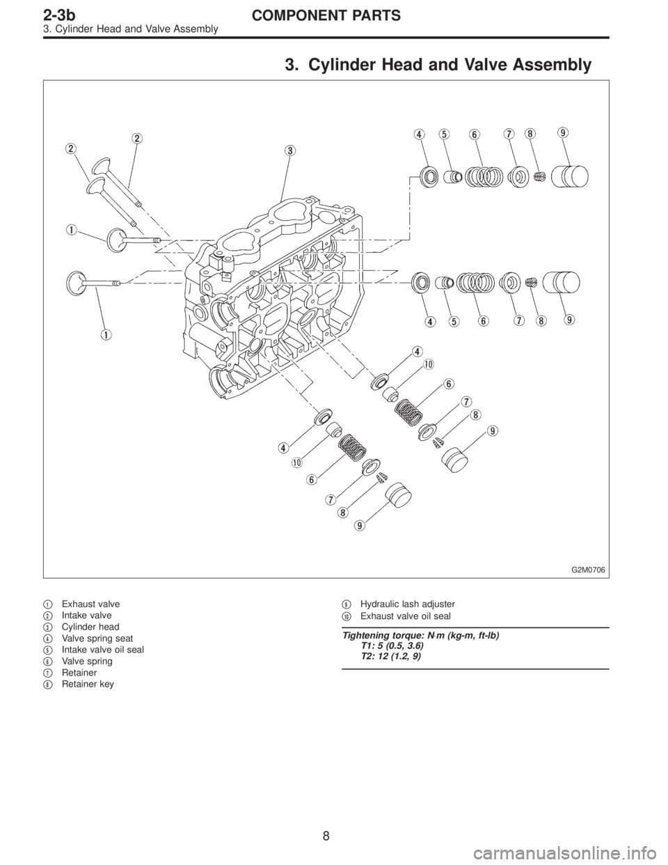
3. Cylinder Head and Valve Assembly
G2M0706
�1Exhaust valve
�
2Intake valve
�
3Cylinder head
�
4Valve spring seat
�
5Intake valve oil seal
�
6Valve spring
�
7Retainer
�
8Retainer key�
9Hydraulic lash adjuster
�
10Exhaust valve oil seal
Tightening torque: N⋅m (kg-m, ft-lb)
T1: 5 (0.5, 3.6)
T2: 12 (1.2, 9)
8
2-3bCOMPONENT PARTS
3. Cylinder Head and Valve Assembly
 Check for cracks and damage visually. Especially,
inspect important parts by means of red lead check.
2) Check the oil passages for clogging.
3) Inspect crankcase su")
 Apply fluid packing to matching surface of oil pump.
Fluid packing:
THREE BOND 1215 or equivalent
(3) Install oil pump on cylinder block. Be careful not to
damage oil seal during installa")