Page 316 of 2890
3. Cylinder Head and Valve Assembly
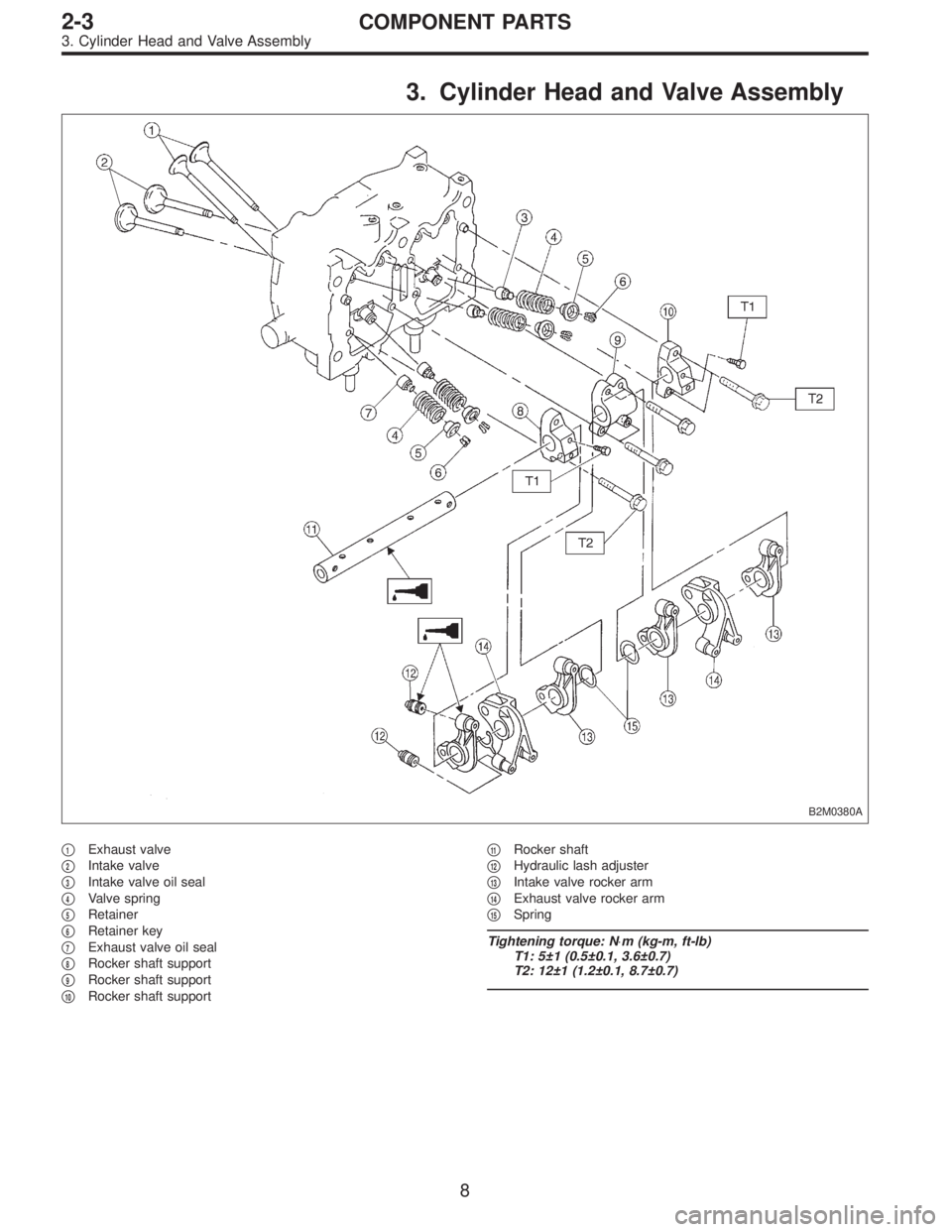
B2M0380A
�1Exhaust valve
�
2Intake valve
�
3Intake valve oil seal
�
4Valve spring
�
5Retainer
�
6Retainer key
�
7Exhaust valve oil seal
�
8Rocker shaft support
�
9Rocker shaft support
�
10Rocker shaft support�
11Rocker shaft
�
12Hydraulic lash adjuster
�
13Intake valve rocker arm
�
14Exhaust valve rocker arm
�
15Spring
Tightening torque: N⋅m (kg-m, ft-lb)
T1: 5±1 (0.5±0.1, 3.6±0.7)
T2: 12±1 (1.2±0.1, 8.7±0.7)
8
2-3COMPONENT PARTS
3. Cylinder Head and Valve Assembly
Page 344 of 2890
 Measure outside diameter of camshaft journal and
inside diameter of cylinder head journal, and determine the
difference between the two (= oil clearance). If oil clear-
ance exceeds specifications,")
3) Measure outside diameter of camshaft journal and
inside diameter of cylinder head journal, and determine the
difference between the two (= oil clearance). If oil clear-
ance exceeds specifications, replace camshaft or cylinder
head as necessary.
Unit: mm (in)
ItemRight-hand camshaft Front Center Rear
Left-hand camshaft Rear Center Front
Clearance at journalStandard 0.055—0.090 (0.0022—0.0035 )
Limit 0.10 (0.0039 )
Camshaft journal O.D.31.935—31.950
(1.2573—1.2579 )37.435—37.450
(1.4738—1.4744 )37.935—37.950
(1.4935—1.4941 )
Journal hole I.D.32.005—32.025
(1.2600—1.2608 )37.505—37.525
(1.4766—1.4774 )38.005—38.025
(1.4963—1.4970 )
G2M0138
4) Check cam face condition; remove minor faults by
grinding with oil stone. Measure the cam height H; replace
if the limit has been exceeded.
Cam height: H
Standard
IN: 31.994—32.094 mm (1.2596—1.2635 in)
EX: 32.624—32.724 mm (1.2844—1.2883 in)
Limit
IN: 31.844 mm (1.2537 in)
EX: 32.474 mm (1.2785 in)
G2M0139
2. CAMSHAFT SUPPORT
Measure the thrust clearance of camshaft with dial gauge.
If the clearance exceeds the limit, replace camshaft sup-
port.
Standard:
0.030—0.260 mm (0.0012—0.0102 in)
Limit:
0.35 mm (0.0138 in)
35
2-3SERVICE PROCEDURE
5. Camshaft
Page 347 of 2890
3. RELATED PARTS
1) Install valve rocker assembly.
B2M0418B
Tightening torque: N⋅m (kg-m, ft-lb)
T1: 5±1 (0.5±0.1, 3.6±0.7)
T2: 12±1 (1.2±0.1, 8.7±0.7)
2) Install timing belt, camshaft sprockets and related parts.
6. Cylinder Head
A: REMOVAL
1. INTAKE MANIFOLD
1) Release fuel pressure.
2) Drain engine coolant.
3) Remove intake manifold.
4) Remove engine coolant pipe.
38
2-3SERVICE PROCEDURE
5. Camshaft - 6. Cylinder Head
Page 348 of 2890
3. RELATED PARTS
1) Install valve rocker assembly.
B2M0418B
Tightening torque: N⋅m (kg-m, ft-lb)
T1: 5±1 (0.5±0.1, 3.6±0.7)
T2: 12±1 (1.2±0.1, 8.7±0.7)
2) Install timing belt, camshaft sprockets and related parts.
6. Cylinder Head
A: REMOVAL
1. INTAKE MANIFOLD
1) Release fuel pressure.
2) Drain engine coolant.
3) Remove intake manifold.
4) Remove engine coolant pipe.
38
2-3SERVICE PROCEDURE
5. Camshaft - 6. Cylinder Head
Page 349 of 2890
2. CYLINDER HEAD
B2M0119A
1) Remove timing belt, camshaft sprocket and related
parts.
2) Remove oil level gauge guide attaching bolt (left hand
only) and oil level gauge guide.
B2M0120A
3) Remove cylinder head bolts in numerical sequence
shown in Figure.
CAUTION:
Leave bolts�
1and�3engaged by three or four threads
to prevent cylinder head from falling.
4) While tapping cylinder head with a plastic hammer,
separate it from cylinder block.
Remove bolts�
1and�3to remove cylinder head.
5) Remove cylinder head gasket.
CAUTION:
Do not scratch the mating surface of cylinder head and
cylinder block.
6) Similarly, remove right side cylinder head.
39
2-3SERVICE PROCEDURE
6. Cylinder Head
Page 350 of 2890
B: DISASSEMBLY
B2M0121A
1) Remove rocker cover.
2) Remove valve rocker assembly.
3) Remove camshaft and support.
4) Place cylinder head on ST.
ST 498267200 CYLINDER HEAD TABLE
B2M0386A
5) Set ST on valve spring. Compress valve spring and
remove the valve spring retainer key. Remove each valve
and valve spring.
ST 499718000 VALVE SPRING REMOVER
CAUTION:
�Mark each valve to prevent confusion.
�Use extreme care not to damage the lips of the
intake valve oil seals and exhaust valve oil seals.
6) Removal of plug (cylinder head LH)
CAUTION:
Do not remove plug unless necessary.
40
2-3SERVICE PROCEDURE
6. Cylinder Head
Page 351 of 2890
 Make sure that no crack or other damage exists. In
addition to visual inspection, inspect important areas by
means of red lead check.
Also make sure that gasket insta")
C: INSPECTION
1. CYLINDER HEAD
1) Make sure that no crack or other damage exists. In
addition to visual inspection, inspect important areas by
means of red lead check.
Also make sure that gasket installing surface shows no
trace of gas and water leaks.
2) Place cylinder head on ST.
ST 498267200 CYLINDER HEAD TABLE
G2M0148
3) Measure the warping of the cylinder head surface that
mates with crankcase by using a straight edge and thick-
ness gauge.
If the warping exceeds 0.05 mm (0.0020 in), regrind the
surface with a surface grinder.
Warping limit:
0.05 mm (0.0020 in)
Grinding limit:
0.1 mm (0.004 in)
Standard height of cylinder head:
98.3 mm (3.870 in)
CAUTION:
Uneven torque for the cylinder head bolts can cause
warping. When reassembling, pay special attention to
the torque so as to tighten evenly.
G2M0149
B2M0074
2. VALVE SEAT
Inspect intake and exhaust valve seats, and correct the
contact surfaces with valve seat cutter if they are defective
or when valve guides are replaced.
Valve seat width: W
Intake
Standard
0.7 mm (0.028 in)
Limit
1.4 mm (0.055 in)
Exhaust
Standard
1.4 mm (0.055 in)
Limit
1.8 mm (0.071 in)
41
2-3SERVICE PROCEDURE
6. Cylinder Head
Page 352 of 2890
 Check the clearance between valve guide and stem.
The clearance can be checked by measuring the outside
diameter of valve stem and the inside diameter of valve
guid")
B2M0387A
B2M0076A
3. VALVE GUIDE
1) Check the clearance between valve guide and stem.
The clearance can be checked by measuring the outside
diameter of valve stem and the inside diameter of valve
guide with outside and inside micrometers respectively.
Clearance between the valve guide and valve stem:
Standard
Intake
0.035—0.062 mm (0.0014—0.0024 in)
Exhaust
0.040—0.067 mm (0.0016—0.0026 in)
Limit
0.15 mm (0.0059 in)
Valve guide inner diameter:
6.000—6.012 mm (0.2362—0.2367 in)
Valve stem outer diameters:
Intake
5.950—5.965 mm (0.2343—0.2348 in)
Exhaust
5.945—5.960 mm (0.2341—0.2346 in)
G2M0150
2) If the clearance between valve guide and stem exceeds
the specification, replace guide as follows:
(1) Place cylinder head on ST1 with the combustion
chamber upward so that valve guides enter the holes
in ST1.
(2) Insert ST2 into valve guide and press it down to
remove valve guide.
ST1 498267200 CYLINDER HEAD TABLE
ST2 499767200 VALVE GUIDE REMOVER
G2M0151
(3) Turn cylinder head upside down and place ST as
shown in the Figure.
ST 499767000 VALVE GUIDE ADJUSTER
B2M0388A
(4) Before installing new oversize valve guide, make
sure that neither scratches nor damages exist on the
inside surface of the valve guide holes in cylinder head.
(5) Put new valve guide, coated with sufficient oil, in
cylinder, and insert ST1 into valve guide. Press in until
the valve guide upper end is flush with the upper sur-
face of ST2.
ST1 499767200 VALVE GUIDE REMOVER
ST2 499767000 VALVE GUIDE ADJUSTER
42
2-3SERVICE PROCEDURE
6. Cylinder Head
![SUBARU LEGACY 1996 Service Repair Manual 3. RELATED PARTS
1) Install valve rocker assembly.
<Ref. to 2-3 [W4E0].>
B2M0418B
Tightening torque: N⋅m (kg-m, ft-lb)
T1: 5±1 (0.5±0.1, 3.6±0.7)
T2: 12±1 (1.2±0.1, 8.7±0.7)
2) Install timing](/manual-img/17/57433/w960_57433-346.png "SUBARU LEGACY 1996 Service Repair Manual 3. RELATED PARTS
1) Install valve rocker assembly.
<Ref. to 2-3 [W4E0].>
B2M0418B
Tightening torque: N⋅m (kg-m, ft-lb)
T1: 5±1 (0.5±0.1, 3.6±0.7)
T2: 12±1 (1.2±0.1, 8.7±0.7)
2) Install timing")
![SUBARU LEGACY 1996 Service Repair Manual 3. RELATED PARTS
1) Install valve rocker assembly.
<Ref. to 2-3 [W4E0].>
B2M0418B
Tightening torque: N⋅m (kg-m, ft-lb)
T1: 5±1 (0.5±0.1, 3.6±0.7)
T2: 12±1 (1.2±0.1, 8.7±0.7)
2) Install timing](/manual-img/17/57433/w960_57433-347.png "SUBARU LEGACY 1996 Service Repair Manual 3. RELATED PARTS
1) Install valve rocker assembly.
<Ref. to 2-3 [W4E0].>
B2M0418B
Tightening torque: N⋅m (kg-m, ft-lb)
T1: 5±1 (0.5±0.1, 3.6±0.7)
T2: 12±1 (1.2±0.1, 8.7±0.7)
2) Install timing")
![SUBARU LEGACY 1996 Service Repair Manual 2. CYLINDER HEAD
B2M0119A
1) Remove timing belt, camshaft sprocket and related
parts.
<Ref. to 2-3 [W3A0].>
2) Remove oil level gauge guide attaching bolt (left hand
only) and oil level gauge guide.
B](/manual-img/17/57433/w960_57433-348.png "SUBARU LEGACY 1996 Service Repair Manual 2. CYLINDER HEAD
B2M0119A
1) Remove timing belt, camshaft sprocket and related
parts.
<Ref. to 2-3 [W3A0].>
2) Remove oil level gauge guide attaching bolt (left hand
only) and oil level gauge guide.
B")
![SUBARU LEGACY 1996 Service Repair Manual B: DISASSEMBLY
B2M0121A
1) Remove rocker cover.
2) Remove valve rocker assembly.
<Ref. to 2-3 [W4A0].>
3) Remove camshaft and support.
<Ref. to 2-3 [W5A0].>
4) Place cylinder head on ST.
ST 498267200](/manual-img/17/57433/w960_57433-349.png "SUBARU LEGACY 1996 Service Repair Manual B: DISASSEMBLY
B2M0121A
1) Remove rocker cover.
2) Remove valve rocker assembly.
<Ref. to 2-3 [W4A0].>
3) Remove camshaft and support.
<Ref. to 2-3 [W5A0].>
4) Place cylinder head on ST.
ST 498267200")