Page 1378 of 2890
2. Evaporator Unit
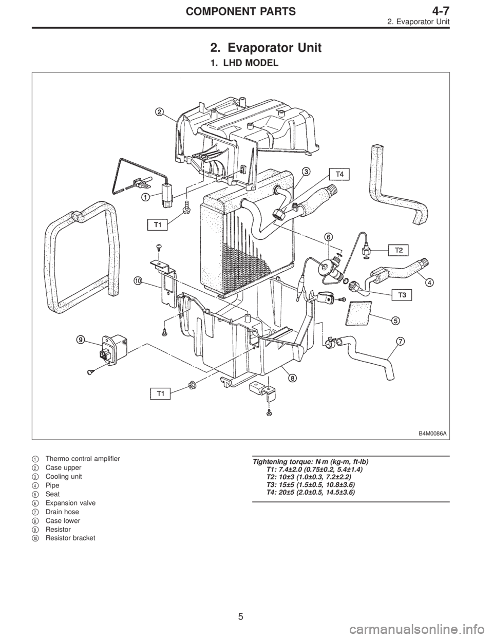
1. LHD MODEL
B4M0086A
�1Thermo control amplifier
�
2Case upper
�
3Cooling unit
�
4Pipe
�
5Seat
�
6Expansion valve
�
7Drain hose
�
8Case lower
�
9Resistor
�
10Resistor bracket
Tightening torque: N⋅m (kg-m, ft-lb)
T1: 7.4±2.0 (0.75±0.2, 5.4±1.4)
T2: 10±3 (1.0±0.3, 7.2±2.2)
T3: 15±5 (1.5±0.5, 10.8±3.6)
T4: 20±5 (2.0±0.5, 14.5±3.6)
5
4-7COMPONENT PARTS
2. Evaporator Unit
Page 1379 of 2890
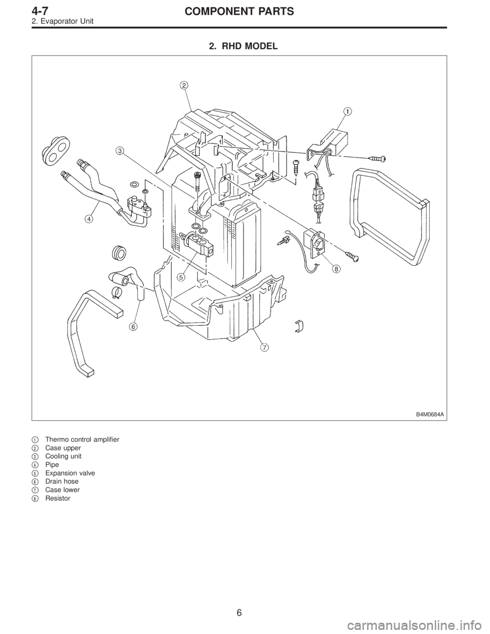
2. RHD MODEL
B4M0684A
�1Thermo control amplifier
�
2Case upper
�
3Cooling unit
�
4Pipe
�
5Expansion valve
�
6Drain hose
�
7Case lower
�
8Resistor
6
4-7COMPONENT PARTS
2. Evaporator Unit
Page 1382 of 2890

1. Safety Precautions
1. HFC-134a AIR CONDITIONING SYSTEM
Component parts of the cooling system, refrigerant, com-
pressor oil, and other parts are not the same for the HFC-
134a system and the older CFC-12 system. Do not inter-
change parts or liquid.
Vehicles with HFC-134a air conditioning systems, use only
HFC-134a parts that are indicated on a label attached to
the vehicle. Before performing any maintenance, verify the
type of air conditioning system installed in the vehicle.
B4M0780
2. COMPRESSOR OIL
Do not use any compressor oil that is not specifically des-
ignated for the HFC-134a air conditioning system; only use
ZXL200PG. Also, do not use HFC-134a compressor oil in
the CFC-12 air conditioning system. If compression oils are
mixed, poor lubrication will result and the compressor itself
may be damaged.
Because HFC-134a compressor oil is very hygroscopic
(easily absorbs moisture), when parts of the air condition-
ing system are being removed, quickly install a blind plug
to prevent contact with the outside air. Also, always make
sure that the service container for compressor oil is tightly
closed except when in use. Store compressor oil in a tightly
closed steel container.
9
4-7SERVICE PROCEDURE
1. Safety Precautions
Page 1419 of 2890

2. Performance Test Diagnosis
If various conditions caused to other air conditioning
system, the characteristics revealed on manifold gauge
reading are shown in the following:
As to the method of a performance test, refer to the item
of“Performance Test”.
Each shaded area on the following tables indicates a read-
ing of the normal system when the temperature of outside
air is 32.5°C (91°F).
Condition Probable cause Corrective action
INSUFFICIENT REFRIGERANT CHARGE
G4M0673
Insufficient cooling Refrigerant is small, or
leaking a little.1. Perform leak test.
2. Repair leak.
3. Charge system.
Evacuate, as
necessary, and
recharge system.
ALMOST NO REFRIGERANT
G4M0674
No cooling action Serious refrigerant leak.Stop compressor
immediately.
1. Perform leak test.
2. Discharge system.
3. Repair leak(s).
4. Replace receiver
drier if necessary.
5. Check oil level.
6. Evacuate and
recharge system.
FAULTY EXPANSION VALVE
G4M0675
Slight cooling;
Sweating or frosted
expansion valve inlet.Expansion valve
restricts refrigerant flow.
�Expansion valve is
clogged.
�Expansion valve is
inoperative.
Valve stuck closed.
Thermal bulb has lost
charge.If valve inlet reveals
sweat or frost:
1. Discharge system.
2. Remove valve and
clean it. Replace it if
necessary.
3. Evacuate system.
4. Charge system.
If valve does not oper-
ate:
1. Discharge system.
2. Replace valve.
3. Evacuate and charge
system.
42
4-7DIAGNOSTICS
2. Performance Test Diagnosis
Page 1420 of 2890

Condition Probable cause Corrective action
G4M0676
G4M0677
Insufficient cooling;
Sweated suction line.
No cooling;
Sweating or frosted suc-
tion line.Expansion valve allows
too much refrigerant
through evaporator.
Faulty seal of O-ring in
expansion valve.Check valve for opera-
tion. If suction side does
not show a pressure
decrease, replace valve.
1. Discharge system.
2. Remove expansion
valve and replace
O-ring.
3. Evacuate and
replace system.
AIR IN SYSTEM
G4M0678
Insufficient cooling Air mixed with refriger-
ant in system.1. Discharge system.
2. Replace receiver
drier.
3. Evacuate and charge
system.
MOISTURE IN SYSTEM
G4M0679
After operation for a
while, pressure on suc-
tion side may show
vacuum pressure read-
ing. During this
condition, discharge air
will be warm. As warn-
ing of this, reading
shows 39 kPa (0.4
kg/cm
2, 6 psi) vibration.Drier is saturated with
moisture. Moisture has
frozen at expansion
valve. Refrigerant flow
is restricted.1. Discharge system.
2. Replace receiver
drier (twice if neces-
sary).
3. Evacuate system
completely. (repeat
30-minute evacuating
three times.)
4. Recharge system.
43
4-7DIAGNOSTICS
2. Performance Test Diagnosis
Page 1421 of 2890

Condition Probable cause Corrective action
FAULTY CONDENSER
G4M0680
No cooling action;
Engine may overheat.
Suction line is very hot.Condenser is often
found not functioning
well.�Check condenser
cooling fan.
�Check condenser for
dirt accumulation.
�Check engine cooling
system for overheat.
�Check for refrigerant
overcharge.
If pressure remains
high in spite of all
above actions taken,
remove and inspect
the condenser for pos-
sible oil clogging.
HIGH-PRESSURE LINE BLOCKED
G4M0681
Insufficient cooling;
Frosted high-pressure
liquid line.Drier is clogged, or
restriction in high-pres-
sure line.1. Discharge system.
2. Remove receiver
drier or strainer and
replace it.
3. Evacuate and charge
system.
FAULTY COMPRESSOR
G4M0682
Insufficient cooling Internal problem is in
compressor, or dam-
aged gasket and valve.1. Discharge system.
2. Remove and check
compressor.
3. Repair or replace
compressor.
4. Check oil level.
5. Replace receiver
drier.
6. Evacuate and charge
system.
44
4-7DIAGNOSTICS
2. Performance Test Diagnosis
Page 1632 of 2890
B6M0482
8) Remove bolts which secure IC regulator, diode and
brush holder.
CAUTION:
Do not apply a shock or load to IC regulator cooling
fins.
G6M0075
C: INSPECTION AND REPAIR
1. ROTOR
1) Slip ring surface
Inspect slip rings for contamination or any roughness of the
sliding surface.
Clean or polish with #500 to #600 emery paper if defective.
B6M0483A
2) Slip ring outside diameter
Measure slip ring outside diameter. If slip ring is worn,
replace rotor.
Slip ring outside diameter:
Standard
27 mm (1.06 in)
Limit
26 mm (1.02 in)
B6M0484A
3) Continuity test
Check continuity between slip rings. If continuity does not
exist, replace rotor.
B6M0485A
4) Insulation test
Check continuity between slip ring and rotor core or shaft.
If continuity exists, replace rotor.
18
6-1SERVICE PROCEDURE
2. Generator
Page 1645 of 2890
B6M0555A
3) Remove #2 spark plug cord by pulling boot, not cord
itself.
4) For subsequent procedures, refer to the procedure for
#1 spark plug.
CAUTION:
When removing spark plug, cover the ATF cooling
pipes with a rag to prevent damage.
G6M0095
3. #3 SPARK PLUG
1) Disconnect battery ground cable.
B6M0557A
2) Disconnect mass air flow sensor connector.
3) Remove four clips securing air cleaner upper cover.
B6M0558
4) Loosen the clamp screw and separate air cleaner upper
cover from air intake duct.
B6M0565A
5) Remove air cleaner element and air cleaner case.
31
6-1SERVICE PROCEDURE
3. Spark Plug
 Remove bolts which secure IC regulator, diode and
brush holder.
CAUTION:
Do not apply a shock or load to IC regulator cooling
fins.
G6M0075
C: INSPECTION AND REPAIR
1. ROTOR
1) Slip ring su")
![SUBARU LEGACY 1996 Service Repair Manual B6M0555A
3) Remove #2 spark plug cord by pulling boot, not cord
itself.
4) For subsequent procedures, refer to the procedure for
#1 spark plug. <Ref. to 6-1 [W3E1].>
CAUTION:
When removing spark plug,](/manual-img/17/57433/w960_57433-1644.png "SUBARU LEGACY 1996 Service Repair Manual B6M0555A
3) Remove #2 spark plug cord by pulling boot, not cord
itself.
4) For subsequent procedures, refer to the procedure for
#1 spark plug. <Ref. to 6-1 [W3E1].>
CAUTION:
When removing spark plug,")