Page 1657 of 2890

1. Precaution
�Before disassembling or reassembling parts, always
disconnect battery ground cable. When repairing
radio, control modules, etc. which are provided with
memory functions, record memory contents before
disconnecting battery ground cable. Otherwise, these
contents are cancelled upon disconnection.
�Reassemble parts in reverse order of disassembly
procedure unless otherwise indicated.
�Adjust parts to specifications contained in this
manual if so designated.
�Connect connectors and hoses securely during
reassembly.
�After reassembly, ensure functional parts operate
smoothly.
CAUTION:
�Airbag system wiring harness is routed near the
electrical parts and switch.
�All Airbag system wiring harness and connectors
are colored yellow. Do not use electrical test equip-
ment on these circuit.
�Be careful not to damage Airbag system wiring har-
ness when servicing the ignition key cylinder.
G6M0102
2. Battery
A: REMOVAL AND INSTALLATION
1. BATTERY
1) Disconnect the positive (+) terminal after disconnecting
the negative (�) terminal of battery.
2) Remove flange nuts from battery rods and take off bat-
tery holder.
3) Remove battery.
Tightening torque:
3.4±1.0 N⋅m (0.35±0.1 kg-m, 2.5±0.7 ft-lb)
NOTE:
�Clean battery cable terminals and apply grease to retard
the formation of corrosion.
�Connect the positive (+) terminal of battery and then the
negative (�) terminal of the battery.
4
6-2SERVICE PROCEDURE
1. Precaution - 2. Battery
Page 1658 of 2890

1. Precaution
�Before disassembling or reassembling parts, always
disconnect battery ground cable. When repairing
radio, control modules, etc. which are provided with
memory functions, record memory contents before
disconnecting battery ground cable. Otherwise, these
contents are cancelled upon disconnection.
�Reassemble parts in reverse order of disassembly
procedure unless otherwise indicated.
�Adjust parts to specifications contained in this
manual if so designated.
�Connect connectors and hoses securely during
reassembly.
�After reassembly, ensure functional parts operate
smoothly.
CAUTION:
�Airbag system wiring harness is routed near the
electrical parts and switch.
�All Airbag system wiring harness and connectors
are colored yellow. Do not use electrical test equip-
ment on these circuit.
�Be careful not to damage Airbag system wiring har-
ness when servicing the ignition key cylinder.
G6M0102
2. Battery
A: REMOVAL AND INSTALLATION
1. BATTERY
1) Disconnect the positive (+) terminal after disconnecting
the negative (�) terminal of battery.
2) Remove flange nuts from battery rods and take off bat-
tery holder.
3) Remove battery.
Tightening torque:
3.4±1.0 N⋅m (0.35±0.1 kg-m, 2.5±0.7 ft-lb)
NOTE:
�Clean battery cable terminals and apply grease to retard
the formation of corrosion.
�Connect the positive (+) terminal of battery and then the
negative (�) terminal of the battery.
4
6-2SERVICE PROCEDURE
1. Precaution - 2. Battery
Page 1716 of 2890

B6M0361A
22. Security System
A: REMOVAL AND INSTALLATION
1. STARTER INTERRUPT RELAY
NOTE:
The starter interrupt relay and headlight alarm relay use the
same parts and are mounted parallel to each other.
Therefore, before removal and installation, identify the
starter interrupt relay by the color of its wiring connection.
1) Remove instrument panel lower cover.
2) Disconnect connector of starter interrupt relay.
3) Remove starter interrupt relay.
4) Installation is in the reverse order of removal.
B6M0361A
2. HEADLIGHT ALARM RELAY
NOTE:
The headlight alarm relay and starter interrupt relay use the
same parts and are mounted parallel to each other.
Therefore, before removal and installation, identify the
headlight alarm relay by the color of its wiring connection.
1) Remove instrument panel lower cover.
2) Disconnect connector of headlight alarm relay.
3) Remove headlight alarm relay.
4) Installation is in the reverse order of removal.
B6M0363A
3. ENGINE HOOD SWITCH
1) Disconnect connector of engine hood switch from bot-
tom side of switch body.
2) Remove headlight (LH).
3) Remove attaching bolt, and then remove engine hood
switch.
4) Installation is in the reverse order of removal.
52
6-2SERVICE PROCEDURE
22. Security System
Page 1727 of 2890
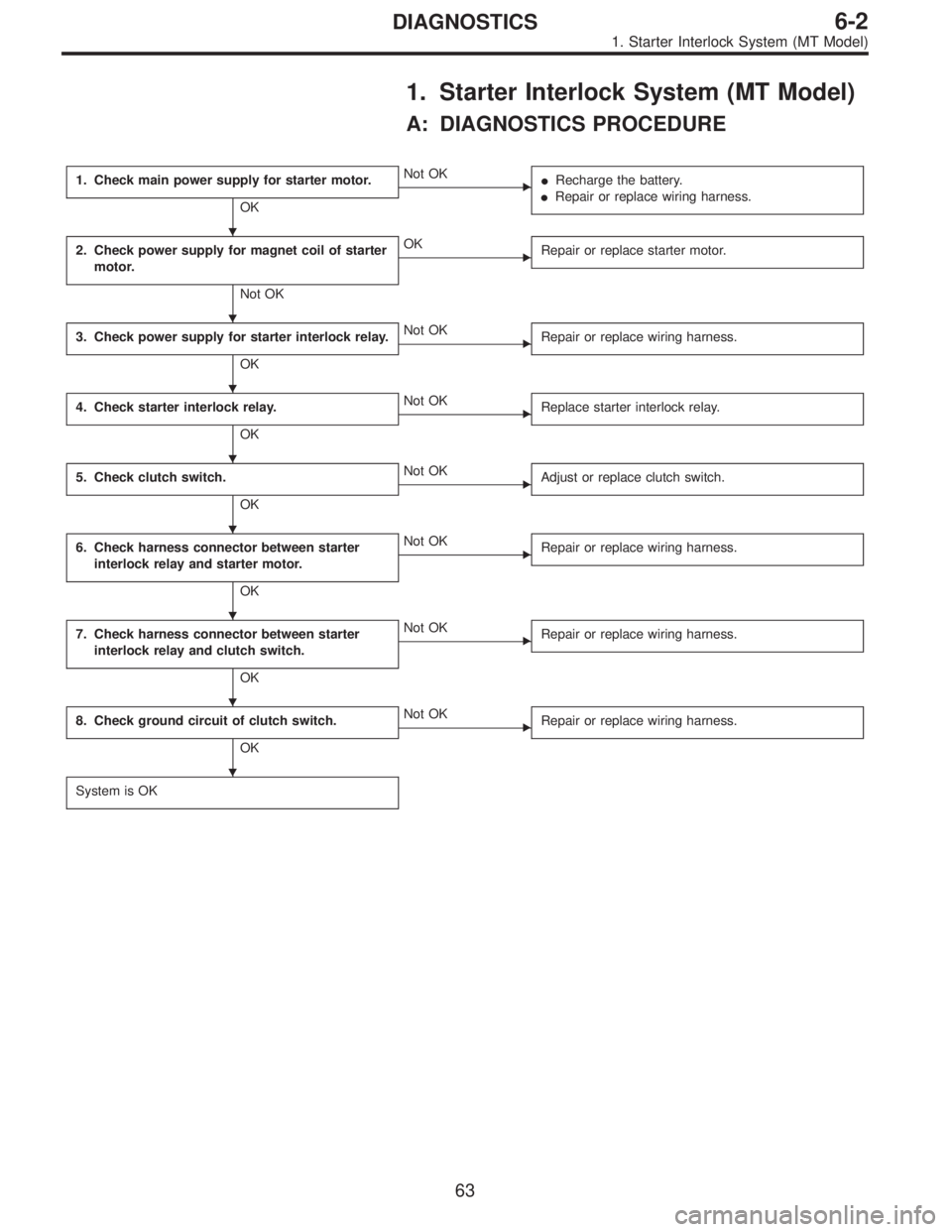
1. Starter Interlock System (MT Model)
A: DIAGNOSTICS PROCEDURE
1. Check main power supply for starter motor.
OK
�Not OK
�Recharge the battery.
�Repair or replace wiring harness.
2. Check power supply for magnet coil of starter
motor.
Not OK
�OK
Repair or replace starter motor.
3. Check power supply for starter interlock relay.
OK
�Not OK
Repair or replace wiring harness.
4. Check starter interlock relay.
OK
�Not OK
Replace starter interlock relay.
5. Check clutch switch.
OK
�Not OK
Adjust or replace clutch switch.
6. Check harness connector between starter
interlock relay and starter motor.
OK
�Not OK
Repair or replace wiring harness.
7. Check harness connector between starter
interlock relay and clutch switch.
OK
�Not OK
Repair or replace wiring harness.
8. Check ground circuit of clutch switch.
OK
�Not OK
Repair or replace wiring harness.
System is OK
�
�
�
�
�
�
�
�
63
6-2DIAGNOSTICS
1. Starter Interlock System (MT Model)
Page 1730 of 2890
2. AT Shift Lock System
A: WIRING DIAGRAM
B6M0466
66
6-2DIAGNOSTICS
2. AT Shift Lock System
Page 1732 of 2890
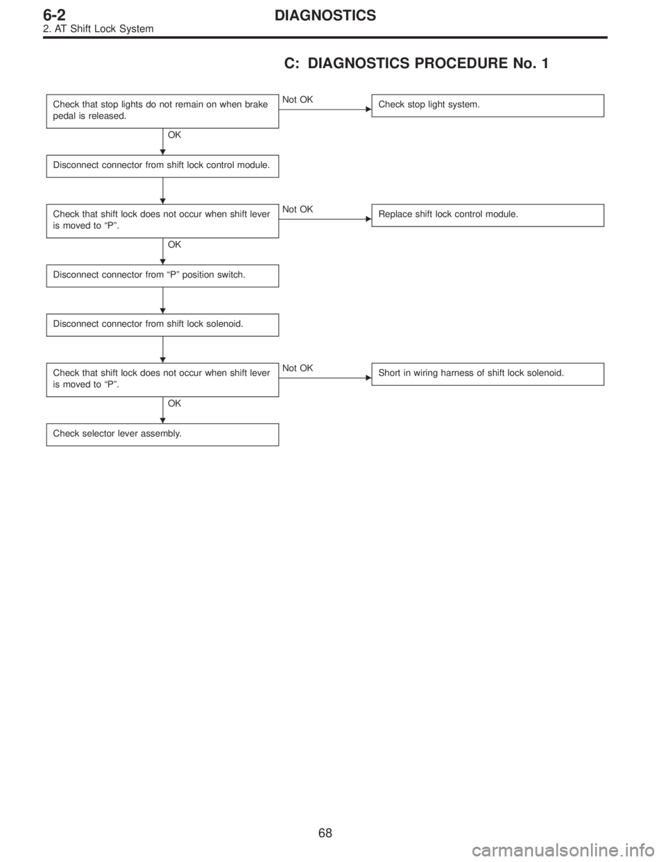
C: DIAGNOSTICS PROCEDURE No. 1
Check that stop lights do not remain on when brake
pedal is released.
OK
�Not OK
Check stop light system.
Disconnect connector from shift lock control module.
Check that shift lock does not occur when shift lever
is moved to“P”.
OK
�Not OK
Replace shift lock control module.
Disconnect connector from“P”position switch.
Disconnect connector from shift lock solenoid.
Check that shift lock does not occur when shift lever
is moved to“P”.
OK
�Not OK
Short in wiring harness of shift lock solenoid.
Check selector lever assembly.
�
�
�
�
�
�
68
6-2DIAGNOSTICS
2. AT Shift Lock System
Page 1733 of 2890

Check if stop light comes on when brake pedal is
depressed.
OK
�Not OK
Check stop light system.
Check if voltage between shift lock contro")
D: DIAGNOSTICS PROCEDURE No. 2 (SHIFT
LOCK DOES NOT RELEASE.)
Check if stop light comes on when brake pedal is
depressed.
OK
�Not OK
Check stop light system.
Check if voltage between shift lock control module
terminal No. 4 and body is at least 10 V when brake
pedal is depressed.
OK
�Not OK
Repair or replace wiring harness or faulty connector
between stop light switch and shift lock control
module.
Check if voltage between shift lock control module
terminal No. 1 and body is at least 10 V when
ignition switch is turned ON.
OK
�Not OK
Check fuse.
Repair or replace wiring harness or faulty connector
between ignition switch and shift lock control
module.
Turn ignition switch OFF.
Disconnect connector from shift lock control module.
Check if continuity exists between terminal No. 2 of
shift lock control module connector and body when
shift lever is set at“P”.
OK
�Not OK
Check inhibitor switch or repair wiring harness.
Check if continuity exists between terminal No. 5 of
shift lock control module connector and body when
shift lever is set at“P”.
OK
�Not OK
Check“P”position switch or repair wiring harness.
Measure resistance between terminal No. 1 of shift
lock control module connector and body.
Resistance is less than 20Ω.
OK
�Not OK
Shift lock solenoid circuit is shorted. Repair or
replace wiring harness or faulty connector between
shift lock solenoid and shift lock control module.
Resistance is at least 10Ω.
OK
�Not OK
Shift lock solenoid is shorted or poorly grounded.
* After repairs, recheck solenoid operation.
If still faulty, replace shift lock control module.
Check if resistance between terminal No. 10 of shift
lock control module connector and body is less than
10Ω.
OK
�Not OK
Shift lock control module ground circuit open or poor
connector contact.
Replace shift lock control module.
�
�
�
�
�
�
�
�
�
�
69
6-2DIAGNOSTICS
2. AT Shift Lock System
Page 1734 of 2890

Check if shift lock operates properly.
OK
�Not OK
Check diagnostics procedure“No. 1”or“No. 2”.
Check if voltage between shift l")
E: DIAGNOSTICS PROCEDURE No. 3 (KEY
INTERLOCK DOES NOT OPERATE.)
Check if shift lock operates properly.
OK
�Not OK
Check diagnostics procedure“No. 1”or“No. 2”.
Check if voltage between shift lock control module
terminal No. 8 and body is at least 10 V when
ignition key is inserted in its slot.
OK
�Not OK
Faulty key switch.
Repair or replace wiring harness or faulty connector
between fuse box and shift lock control module.
Check if voltage between shift lock control module
terminal No. 7 and body is at least 10 V when
ignition switch is set to ACC.
OK
�Not OK
Repair or replace wiring harness or faulty connector
between ignition switch and shift lock control
module.
Disconnect connector from shift lock control module.
Check if resistance between terminal No. 9 and
terminal No. 11 of shift lock control module
connector is less than 8Ω.
OK
�Not OK
Key lock solenoid circuit open. Repair or replace
wiring harness or faulty connector between key lock
solenoid and shift lock control module.
Voltage is at least 4 V. (*)
OK
�Not OK
Key lock solenoid is shorted.
Repair or replace wiring harness or faulty connector
between key lock solenoid and shift lock control
module.
* After repairs, recheck for proper operation.
If still faulty, replace shift lock control module.
Check if resistance between terminal No. 11 of shift
lock control module connector and body is at least 1
MΩ.
OK
�Not OK
Replace shift lock control module.
*: When conducting operational checks of the key lock solenoid, do not apply 12 V to solenoid for more than one second, since
this may break solenoid circuit.
�
�
�
�
�
�
70
6-2DIAGNOSTICS
2. AT Shift Lock System