Page 273 of 2890
WIRING
DIAGRAM
[D6013]
6-3
6
.
Wiring
Diagram
CrankshaftCamshaftpositionpositionsensorsensor
P~2
(
E10
I
Ely
3
3
.
.
.
.
.
.
~r------------'
I
~1
r-----------J
ii
i
i
iI
E1
m~
B20
N
I11II
Eng(ne
control
884
module
m
J
Jm
3
~r
H
YJ
J
(D
JJ
CO
;~
E3
N
NJ
?-J
N
3
N
E17
EB
E6
~
E16
-E5
M
N
E7
~N
E4
#4#3
#2
#1
Fuel
Injector
Idle
air
control
Purge
control
solenoid
valve
solenoid
valve
E15
(Darkgray)
(L
(
ght
gray)
E5
Elb
(L
f
ght
gray)
El0
(Gray)
(Dark
gray)
E6
El7
(Darkgray)
1
2
C
I
D
g84
(L
i
ght
b
l
ue)
1234
5678
910
111213141516
E4
(B
I
ue)
E7
(Gre
)
B20
(L
r
ht
171814202122232425262728293045464748495051525354555657
3132333435363738394041424344
58596061626364656667b96970
yg
gra
y)
123
71
1
72
1
73
1
74
1
75
1
767778
79
80
8182
83
84
1
85
1
86
1
87
1
'9
1
89
1
90
1
9192
1
93
1
94
1
959b
12
123
456
BUR10-03D
9
Page 274 of 2890
6-3
[Dso1s]
WIRING
DIAGRAM
6
.
Wiring
Diagram
16
.
FUEL
GAUGE
SYSTEM
To
Power
Supply
Routing
FB-20
FUSE
Na
15
a
:i
10
Combinationmeter
b
:
i12
c
:
i14
Low-fuel
^^
warning
light
Fuel
gauge
(3
B38
Fuel
gauge
sub
module
R59
E
v
J\
B
Fuel
gauge
module
~I
R58
B22
E3
R
E
S
.
M
.
J
.
[Refer
to
foldout
page
.]
R59R57R58
il4
12
3
123
12
45678
456
12345678910111213
B22
(L
i
ght
gray)
(L
i
ght
gray)
Q
l0
i
12
(L
i
ght
gray)
1
2
34
i3
(Brown)
5678
9101112
1
1
1
2
1
3
45
678910
12345678910111213141516
13141516
1
11
1
12
1
13
1
14
1
15
1
16
1
17
1
18
1
19
1
2
11
9
1
1121314E
;11
6
1
7
F8
~9
1
10
1
11
1
12
1
13
1
14
1
15
1
1
-6
1
1311
BUR61-02
10
Page 275 of 2890
8
.
Electrical
Wiring
Harness
and
Ground
Point
Connector
Connecting
to
No
.
Pole
Color
Area
No
.
Name
R156
B-2
B97
Bulkhead
wiring
harness
(S
.M
.J
.)
R4
1
Black
B-2
Parking
brake
switch
R5
2B-2
Select
lever
illumination
light
R6
2
Black
B-2
Shift
lock
solenoid
R7
2B-2P
position
switch
RS
2B-2
Seat
belt
switch
R9
1
Brown
B-3Front
door
switch
LH
R11
8
B-4D21
Rear
doorcord
LH
R12
1
Brown
B-2
Front
door
switch
RH
R14
8
B-2
D27
Rear
door
cord
RH
R15
8B-3
R57
Fueltank
cord
R16
1
Brown
A-3
Rear
door
switch
RH
R30
2
Black
B-2
Diode
(Rear
gale
latch
switch)
R46
2
B3
R67
Fuel
lankcord
R50
2
Green
B-2
890
Bulkhead
wiring
harness
R52
2
A-3
Room
light
R57
S
B-3
R15
Rear
wiring
harness
R58
6
A-3
Fuel
gaugemodule
&
fuel
pump
R59
2
B-4
Fuel
gauge
submodule
R67
2
B-3
R46
Rear
wiring
harness
R68
2B-3
Pressure
control
solenoid
valve
R69
I
2
A-3
Vent
control
solenoid
valve
non-coiorea
A
B
C
n
6
.
REAR
WIRING
HARNESS
AND
GROUND
POINT
1
I
2
I
3
I
4
2
~S
4
[D806]
B6M0695A
A
B
C
u
Page 276 of 2890
8
.
Electrical
Wiring
Harness
and
Ground
Point
Connector
Connecting
to
No
.
Pole
Color
Area
No
.
Name
R156
B-2
B97
Bulkhead
wiring
harness
(S
.M
.J
.)
R4
1
Black
B-2
Parking
brake
switch
R5
2B-2
Select
lever
illumination
light
R6
2
Black
B-2
Shift
lock
solenoid
R7
2B-2P
position
switch
RS
2B-2
Seat
belt
switch
R9
1
Brown
B-3Front
door
switch
LH
R11
8
B-4D21
Rear
doorcord
LH
R12
1
Brown
B-2
Front
door
switch
RH
R14
8
B-2
D27
Rear
door
cord
RH
R15
8B-3
R57
Fueltank
cord
R16
1
Brown
A-3
Rear
door
switch
RH
R30
2
Black
B-2
Diode
(Rear
gale
latch
switch)
R46
2
B3
R67
Fuel
lankcord
R50
2
Green
B-2
890
Bulkhead
wiring
harness
R52
2
A-3
Room
light
R57
S
B-3
R15
Rear
wiring
harness
R58
6
A-3
Fuel
gaugemodule
&
fuel
pump
R59
2
B-4
Fuel
gauge
submodule
R67
2
B-3
R46
Rear
wiring
harness
R68
2B-3
Pressure
control
solenoid
valve
R69
I
2
A-3
Vent
control
solenoid
valve
non-coiorea
A
B
C
n
6
.
REAR
WIRING
HARNESS
AND
GROUND
POINT
1
I
2
I
3
I
4
2
~S
4
[D806]
B6M0695A
A
B
C
u
Page 277 of 2890
Connector
Connecting
to
No
.
Pole
Color
Area
No
.
Name
R22
1
Brown
C-1
Rear
door
switch
LH
R23
6
G2
Power
antenna
R25
2
Black
C-3
Rear
defogger
condenser
R26
4
Black
D-4
Rear
combination
light
RH
R28
4
Black
C-2
Rear
combination
light
LH
R36
5
Black
C-3
Rear
wiper
relay
R37
2
C-3
D33
R38
4
G3
D34
Rear
gatecord
R39
8
C-4
D35
R47
3
I
D-3
I
Fuel
tank
pressure
sensor
Connector
Connecting
to
No
.
Pole
Color
Area
No
.
Name
D33
2
C-3
R37
D34
4C-3
R38
Rear
wiring
harness
D35
8
C-4
R39
D37
1
Black
B-3L
li
D38
1
B-3
uggage
room
ght
D39
2B-3
High-mounted
stop
light
D40
1
Black
B-4
Rear
defogger
(Power)
D42
4B-4
Rear
finisher
light
RH
D43
48-3
Rear
wiper
motor
D44
2B-4
License
plate
light
RH
D45
2A-3
License
plate
light
LH
D46
2
Black
A-4
Rear
gate
latch
switch
D47
4
A-4
Rear
gate
lock
actuator
D48
1
Black
B-3
Rear
defogger
(Ground)
D49
I
4A-3
Rear
finisher
light
LH
''
Non-colored
9
.
REAR
END
WIRING
HARNESS
AND
GROUND
POINT
1
243
B
C
C
D
B6M069
1
2
3_
I
4
13
11`~~Il'//
Page 278 of 2890
Connector
Connecting
to
No
.
Pole
Color
Area
No
.
Name
R22
1
Brown
C-1
Rear
door
switch
LH
R23
6
G2
Power
antenna
R25
2
Black
C-3
Rear
defogger
condenser
R26
4
Black
D-4
Rear
combination
light
RH
R28
4
Black
C-2
Rear
combination
light
LH
R36
5
Black
C-3
Rear
wiper
relay
R37
2
C-3
D33
R38
4
G3
D34
Rear
gatecord
R39
8
C-4
D35
R47
3
I
D-3
I
Fuel
tank
pressure
sensor
Connector
Connecting
to
No
.
Pole
Color
Area
No
.
Name
D33
2
C-3
R37
D34
4C-3
R38
Rear
wiring
harness
D35
8
C-4
R39
D37
1
Black
B-3L
li
D38
1
B-3
uggage
room
ght
D39
2B-3
High-mounted
stop
light
D40
1
Black
B-4
Rear
defogger
(Power)
D42
4B-4
Rear
finisher
light
RH
D43
48-3
Rear
wiper
motor
D44
2B-4
License
plate
light
RH
D45
2A-3
License
plate
light
LH
D46
2
Black
A-4
Rear
gate
latch
switch
D47
4
A-4
Rear
gate
lock
actuator
D48
1
Black
B-3
Rear
defogger
(Ground)
D49
I
4A-3
Rear
finisher
light
LH
''
Non-colored
9
.
REAR
END
WIRING
HARNESS
AND
GROUND
POINT
1
243
B
C
C
D
B6M069
1
2
3_
I
4
13
11`~~Il'//
Page 484 of 2890

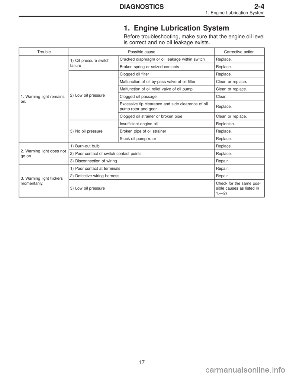
1. Engine Lubrication System
Before troubleshooting, make sure that the engine oil level
is correct and no oil leakage exists.
Trouble Possible cause Corrective action
1. Warning light remains
on.1) Oil pressure switch
failureCracked diaphragm or oil leakage within switch Replace.
Broken spring or seized contacts Replace.
2) Low oil pressureClogged oil filter Replace.
Malfunction of oil by-pass valve of oil filter Clean or replace.
Malfunction of oil relief valve of oil pump Clean or replace.
Clogged oil passage Clean.
Excessive tip clearance and side clearance of oil
pump rotor and gearReplace.
Clogged oil strainer or broken pipe Clean or replace.
3) No oil pressureInsufficient engine oil Replenish.
Broken pipe of oil strainer Replace.
Stuck oil pump rotor Replace.
2. Warning light does not
go on.1) Burn-out bulb Replace.
2) Poor contact of switch contact points Replace.
3) Disconnection of wiring Repair.
3. Warning light flickers
momentarily.1) Poor contact at terminals Repair.
2) Defective wiring harness Repair.
3) Low oil pressureCheck for the same pos-
sible causes as listed in
1.—2)
17
2-4DIAGNOSTICS
1. Engine Lubrication System
Page 505 of 2890

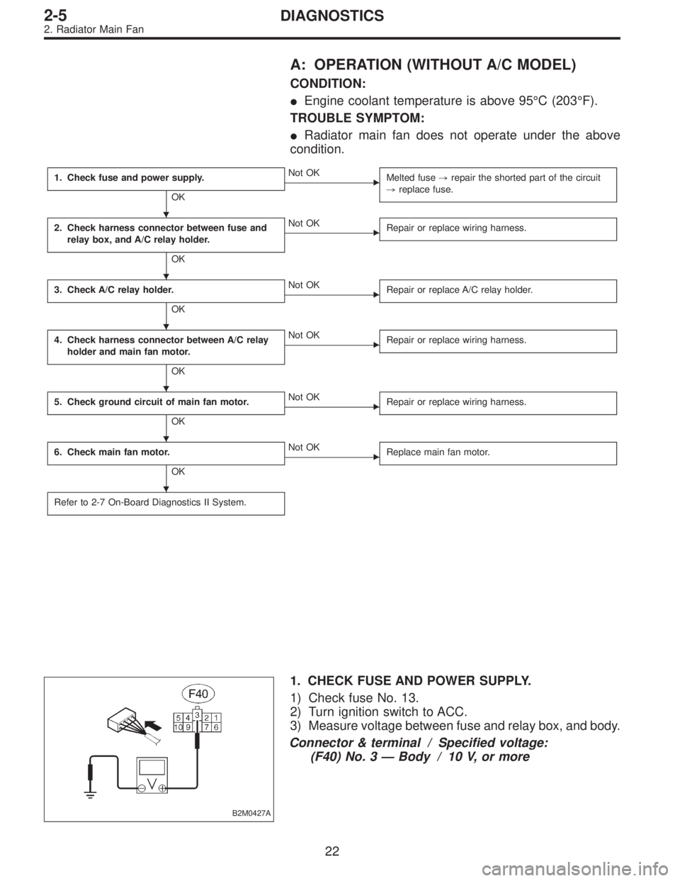
A: OPERATION (WITHOUT A/C MODEL)
CONDITION:
�Engine coolant temperature is above 95°C (203°F).
TROUBLE SYMPTOM:
�Radiator main fan does not operate under the above
condition.
1. Check fuse and power supply.
OK
�Not OK
Melted fuse,repair the shorted part of the circuit
,replace fuse.
2. Check harness connector between fuse and
relay box, and A/C relay holder.
OK
�Not OK
Repair or replace wiring harness.
3. Check A/C relay holder.
OK
�Not OK
Repair or replace A/C relay holder.
4. Check harness connector between A/C relay
holder and main fan motor.
OK
�Not OK
Repair or replace wiring harness.
5. Check ground circuit of main fan motor.
OK
�Not OK
Repair or replace wiring harness.
6. Check main fan motor.
OK
�Not OK
Replace main fan motor.
Refer to 2-7 On-Board Diagnostics II System.
B2M0427A
1. CHECK FUSE AND POWER SUPPLY.
1) Check fuse No. 13.
2) Turn ignition switch to ACC.
3) Measure voltage between fuse and relay box, and body.
Connector & terminal / Specified voltage:
(F40) No. 3—Body / 10 V, or more
�
�
�
�
�
�
22
2-5DIAGNOSTICS
2. Radiator Main Fan