Page 1430 of 2890
1. Supplemental Restraint System
“Airbag”
Airbag system wiring harness is routed on and along body
panels.
CAUTION:
�All Airbag system wiring harness and connectors
are colored yellow. Do not use electrical test equip-
ment on these circuits.
�Be careful not to damage Airbag system wiring har-
ness when repairing the body panel.
2. Body Datum Points
Various master repair locations are established as datum
points used during body repairs. In addition, guide holes,
locators and indents are provided to facilitate panel
replacement and achieve alignment accuracy.
NOTE:
Left and right datum points are all symmetrical to each
other.
2
5-1SERVICE DATA
1. Supplemental Restraint System“Airbag”- 2. Body Datum Points
Page 1467 of 2890
4. Front Bumper
A: REMOVAL
SUPPLEMENTAL RESTRAINT SYSTEM“AIRBAG”
Airbag system wiring harness is routed near the front
bumper assembly.
CAUTION:
�All Airbag system wiring harness and connectors
are colored yellow. Do not use electrical test equip-
ment on these circuits.
�Be careful not to damage Airbag system wiring har-
ness when servicing the front bumper assembly.
B5M0273
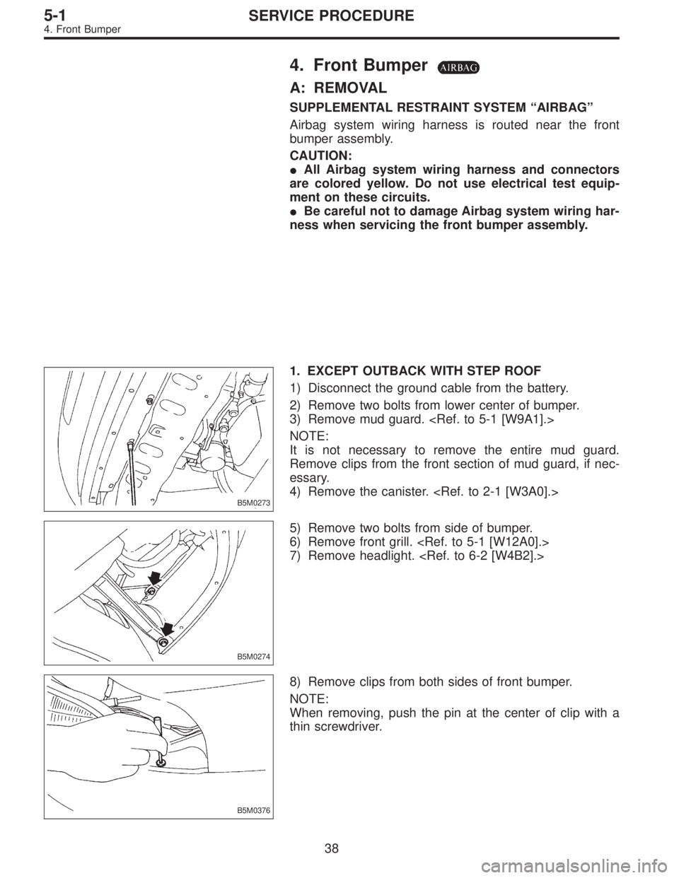
1. EXCEPT OUTBACK WITH STEP ROOF
1) Disconnect the ground cable from the battery.
2) Remove two bolts from lower center of bumper.
3) Remove mud guard.
NOTE:
It is not necessary to remove the entire mud guard.
Remove clips from the front section of mud guard, if nec-
essary.
4) Remove the canister.
B5M0274
5) Remove two bolts from side of bumper.
6) Remove front grill.
7) Remove headlight.
B5M0376
8) Remove clips from both sides of front bumper.
NOTE:
When removing, push the pin at the center of clip with a
thin screwdriver.
38
5-1SERVICE PROCEDURE
4. Front Bumper
Page 1480 of 2890
8. Front Fender
A: REMOVAL
SUPPLEMENTAL RESTRAINT SYSTEM“AIRBAG”
Airbag system wiring harness is routed near the front
fender.
CAUTION:
�All Airbag system wiring harness and connectors
are colored yellow. Do not use electrical test equip-
ment on these circuits.
�Be careful not to damage Airbag system wiring har-
ness when servicing the front fender.
B5M0285A
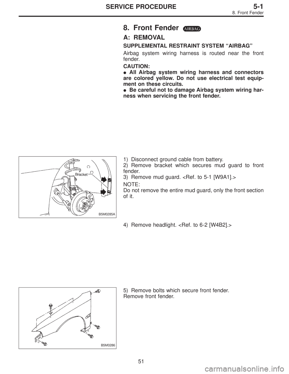
1) Disconnect ground cable from battery.
2) Remove bracket which secures mud guard to front
fender.
3) Remove mud guard.
NOTE:
Do not remove the entire mud guard, only the front section
of it.
4) Remove headlight.
B5M0286
5) Remove bolts which secure front fender.
Remove front fender.
51
5-1SERVICE PROCEDURE
8. Front Fender
Page 1481 of 2890
G5M0175
B: INSTALLATION
1) Installation is in the reverse order of removal.
2) Check for alignment of front fender with hood and front
door with front fender at all points. Adjust, if necessary.
B5M0287A
9. Mud Guard and Rear Arch
Protector
A: REMOVAL
SUPPLEMENTAL RESTRAINT SYSTEM“AIRBAG”
Airbag system wiring harness is routed near the mud
guard.
CAUTION:
�All Airbag system wiring harness and connectors
are colored yellow. Do not use electrical test equip-
ment on these circuits.
�Be careful not to damage Airbag system wiring har-
ness when servicing the mud guard.
B5M0288
1. MUD GUARD (EXCEPT OUTBACK WITH STEP
ROOF)
1) Jack-up vehicle to remove tire.
2) Remove screws and clips. Move mud guard toward the
center of the body and remove mud guard.
52
5-1SERVICE PROCEDURE
8. Front Fender - 9. Mud Guard and Rear Arch Protector
Page 1482 of 2890
G5M0175
B: INSTALLATION
1) Installation is in the reverse order of removal.
2) Check for alignment of front fender with hood and front
door with front fender at all points. Adjust, if necessary.
B5M0287A
9. Mud Guard and Rear Arch
Protector
A: REMOVAL
SUPPLEMENTAL RESTRAINT SYSTEM“AIRBAG”
Airbag system wiring harness is routed near the mud
guard.
CAUTION:
�All Airbag system wiring harness and connectors
are colored yellow. Do not use electrical test equip-
ment on these circuits.
�Be careful not to damage Airbag system wiring har-
ness when servicing the mud guard.
B5M0288
1. MUD GUARD (EXCEPT OUTBACK WITH STEP
ROOF)
1) Jack-up vehicle to remove tire.
2) Remove screws and clips. Move mud guard toward the
center of the body and remove mud guard.
52
5-1SERVICE PROCEDURE
8. Front Fender - 9. Mud Guard and Rear Arch Protector
Page 1561 of 2890
![SUBARU LEGACY 1996 Service Repair Manual B5M0045
8. REAR QUARTER PILLAR LOWER
<Ref. to 5-3 [C500].>
1) Set rear seat cushion up.
2) Remove side sill rear upper cover.
3) Remove rear seat belt. (Upper anchor and lower anchor
bolts)
4) Remove](/manual-img/17/57433/w960_57433-1560.png "SUBARU LEGACY 1996 Service Repair Manual B5M0045
8. REAR QUARTER PILLAR LOWER
<Ref. to 5-3 [C500].>
1) Set rear seat cushion up.
2) Remove side sill rear upper cover.
3) Remove rear seat belt. (Upper anchor and lower anchor
bolts)
4) Remove")
B5M0045
8. REAR QUARTER PILLAR LOWER
1) Set rear seat cushion up.
2) Remove side sill rear upper cover.
3) Remove rear seat belt. (Upper anchor and lower anchor
bolts)
4) Remove side skirt trim.
5) Remove cap strut.
6) Remove rear quarter upper rear trim.
7) Remove rear quarter pillar lower trim.
8) Installation is in the reverse order of removal.
CAUTION:
Be careful not to ride trim panel over harness,
insulators, etc.
B5M0050
9. ROOF TRIM
1) Remove room mirror, room light, sun visor and assist
grip.
2) Remove front pillar upper, center pillar upper, rear quar-
ter upper and rear rail trim.
3) Using ST, remove clips and then detach roof trim.
ST 925580000 PULLER
4) Installation is in the reverse order of removal.
CAUTION:
When removing clip, use great care to prevent damag-
ing the roof trim.
10. FLOOR MAT
Supplemental Restraint System“Airbag”
Airbag system wiring harness is routed near floor mat.
CAUTION:
�All Airbag system wiring harness and connectors
are colored yellow. Do not use electrical test equip-
ment on these circuit.
�Be careful not to damage Airbag system wiring har-
ness when servicing floor mat.
The following procedure is applicable to all models.
15
5-3SERVICE PROCEDURE
5. Inner Trim Panel
Page 1566 of 2890
1. Instrument Panel
Airbag system wiring harness is routed near combination
meter.
CAUTION:
�All Airbag system wiring harness and connectors
are colored yellow. Do not use electrical test equip-
ment on these circuits.
�Be careful not to damage Airbag system wiring har-
ness when servicing the combination meter.
B5M0022A
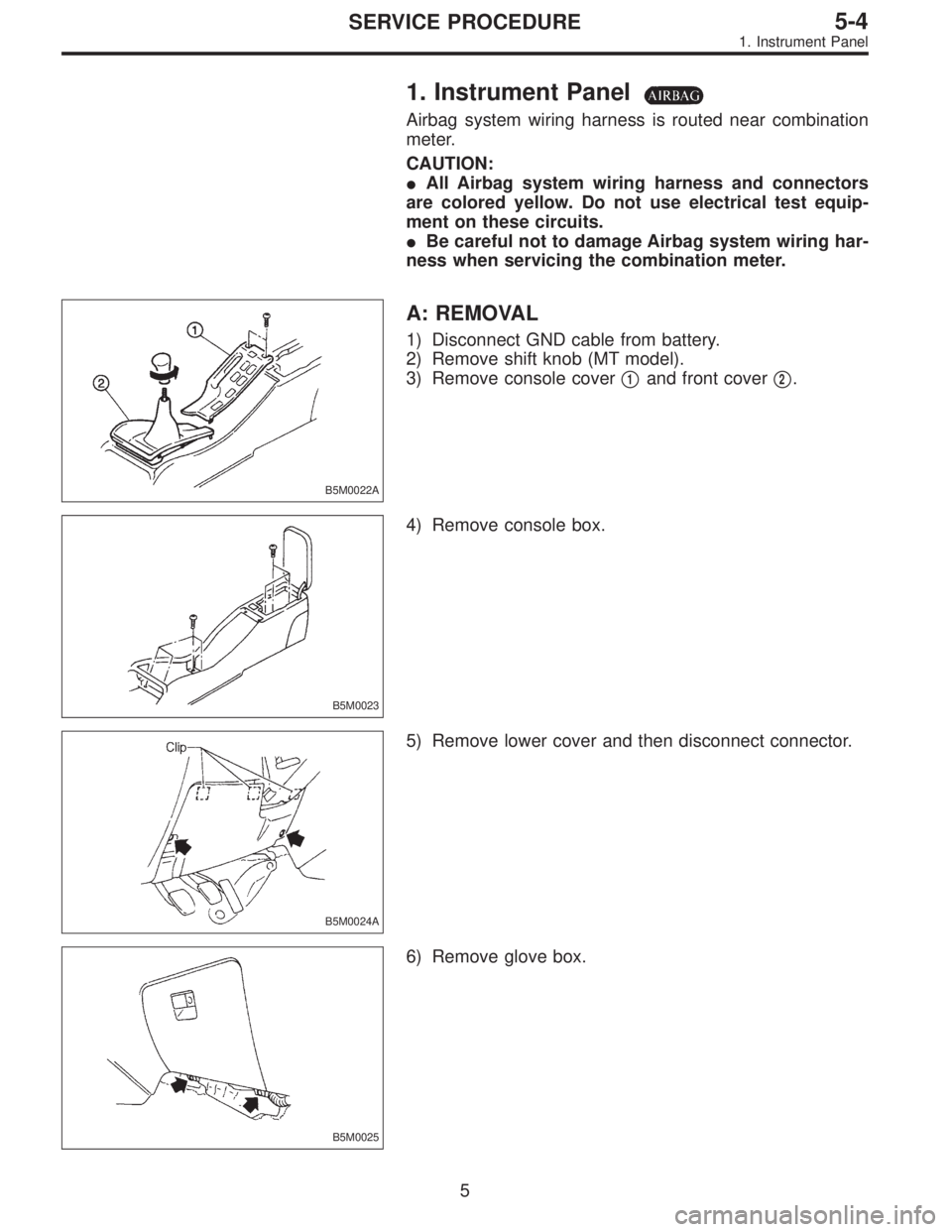
A: REMOVAL
1) Disconnect GND cable from battery.
2) Remove shift knob (MT model).
3) Remove console cover�
1and front cover�2.
B5M0023
4) Remove console box.
B5M0024A
5) Remove lower cover and then disconnect connector.
B5M0025
6) Remove glove box.
5
5-4SERVICE PROCEDURE
1. Instrument Panel
Page 1584 of 2890
G5M0312
3) Remove lower cover.
Disconnect airbag connector (AB3) and (AB8) below steer-
ing column.
CAUTION:
Do not reconnect airbag connector at steering column
until front sensors are securely re-installed.
G5M0313
4) Remove console box. Discon-
nect 2-pin blue connector (AB4) (right side front sensor)
and 2-pin orange connector (AB5) (left side front sensor)
from airbag control module.
G5M0314
5) Roll up floor mat and side sill cover.
[W5A10].> Remove front sensor harness from clip and pro-
tector.
6) Remove front wheels.
7) Remove front mud guard.
G5M0315
8) Remove wiring harness clips.
G5M0316
9) Remove grommet.
14
5-5SERVICE PROCEDURE
4. Front Sensor
 Installation is in the reverse order of removal.
2) Check for alignment of front fender with hood and front
door with front fender at all points. Adjust, if necessary.
B5M02")
 Installation is in the reverse order of removal.
2) Check for alignment of front fender with hood and front
door with front fender at all points. Adjust, if necessary.
B5M02")
![SUBARU LEGACY 1996 Service Repair Manual G5M0312
3) Remove lower cover. <Ref. to 5-4 [W1A0].>
Disconnect airbag connector (AB3) and (AB8) below steer-
ing column.
CAUTION:
Do not reconnect airbag connector at steering column
until front sens](/manual-img/17/57433/w960_57433-1583.png "SUBARU LEGACY 1996 Service Repair Manual G5M0312
3) Remove lower cover. <Ref. to 5-4 [W1A0].>
Disconnect airbag connector (AB3) and (AB8) below steer-
ing column.
CAUTION:
Do not reconnect airbag connector at steering column
until front sens")