Page 1766 of 2890

M: DIAGNOSTICS PROCEDURE FOR HORN
ALARM SIGNAL
1. Check horn alarm output signal for security
control module.
Not OK
�OK
5. Check horn relay.
OK Not OK
Repair or replace
wiring harness of horn
circuit.
Replace horn relay.
2. Check power supply for horn relay.
OK
�Not OK
Repair or replace wiring harness between horn
relay and battery.
3. Check continuity of horn relay.
OK
�Not OK
Replace horn relay.
4. Check harness connector between horn relay
and security control module.
OK
�Not OK
Repair or replace wiring harness between horn
relay and security control module.
Replace security control module.
B6M0461A
1. CHECK HORN ALARM OUTPUT SIGNAL FOR
SECURITY CONTROL MODULE.
1) Remove security control module without disconnecting
connector.
2) Measure voltage between security control module con-
nector and body.
Connector & terminal / Specified voltage:
(B93) No. 13—Body / 10 V, or more
3) Set security system in armed state.
4) Open the door without ignition key to operate the secu-
rity system (alarm state).
5) Measure voltage between security control module and
body during alarm state.
Connector & terminal / Specified voltage:
(B93) No. 13—Body / repeats 1 V, max. (0.2 sec.)
and 10 V, or more (0.6 sec.)
intervals
��
�
�
�
�
102
6-2DIAGNOSTICS
6. Security System
Page 1768 of 2890

N: DIAGNOSTICS PROCEDURE FOR
HEADLIGHT ALARM SIGNAL
1. Check headlight alarm output signal for security
control module.
Not OK
�OK
5. Check headlight alarm relay.
OK Not OK
Repair or replace
wiring harness of
headlight circuit.
Replace headlight
alarm relay.
2. Check power supply for headlight alarm relay.
OK
�Not OK
Repair or replace wiring harness between
headlight alarm relay and battery.
3. Check continuity of headlight alarm relay.
OK
�Not OK
Replace headlight alarm relay.
4. Check harness connector between headlight
alarm relay and security control module.
OK
�Not OK
Repair or replace wiring harness between
headlight alarm relay and security control
module.
Replace security control module.
B6M0457A
1. CHECK HEADLIGHT ALARM OUTPUT SIGNAL
FOR SECURITY CONTROL MODULE.
1) Remove security control module without disconnecting
connector.
2) Measure voltage between security control module con-
nector and body.
Connector & terminal / Specified voltage:
(B93) No. 12—Body / 10 V, or more
3) Set security system in armed state.
4) Open the door without ignition key to operate the secu-
rity system (alarm state).
5) Measure voltage between security control module and
body during alarm state.
Connector & terminal / Specified voltage:
(B93) No. 12—Body / repeats 1 V, max. (0.2 sec.)
and 10 V, or more (0.6 sec.)
intervals
��
�
�
�
�
104
6-2DIAGNOSTICS
6. Security System
Page 1835 of 2890
, main relay and fuel pump relay.
CAUTION:
�All Airbag system wirin")
4. Cautions
A: SUPPLEMENTAL RESTRAINT SYSTEM
“AIRBAG”
Airbag system wiring harness is routed near the engine
control module (ECM), main relay and fuel pump relay.
CAUTION:
�All Airbag system wiring harness and connectors
are colored yellow. Do not use electrical test equip-
ment on these circuit.
�Be careful not to damage Airbag system wiring har-
ness when servicing the engine control module (ECM),
transmission control module (TCM), main relay and
fuel pump relay.
B: PRECAUTIONS
1) Never connect the battery in reverse polarity.
�The ECM will be destroyed instantly.
�The fuel injector and other part will be damaged in just
a few minutes more.
2) Do not disconnect the battery terminals while the
engine is running.
�A large counter electromotive force will be generated in
the alternator, and this voltage may damage electronic
parts such as ECM, etc.
3) Before disconnecting the connectors of each sensor
and the ECM, be sure to turn OFF the ignition switch.
4) Before removing ECM from the located position, dis-
connect two cables on battery.
�Otherwise, the ECM may be damaged.
5) The connectors to each sensor in the engine compart-
ment and the harness connectors on the engine side and
body side are all designed to be waterproof. However, it is
still necessary to take care not to allow water to get into the
connectors when washing the vehicle, or when servicing
the vehicle on a rainy day.
H2M1154A
6) Use ECM mounting stud bolts at the body head ground-
ing point when measuring voltage and resistance inside the
passenger compartment.
67
2-7ON-BOARD DIAGNOSTICS II SYSTEM
4. Cautions
Page 1847 of 2890
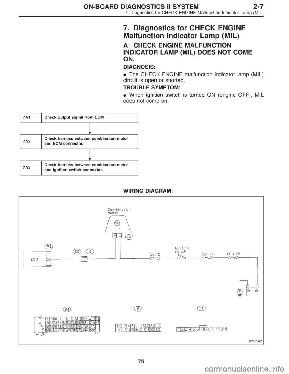
7. Diagnostics for CHECK ENGINE
Malfunction Indicator Lamp (MIL)
A: CHECK ENGINE MALFUNCTION
INDICATOR LAMP (MIL) DOES NOT COME
ON.
DIAGNOSIS:
�The CHECK ENGINE malfunction indicator lamp (MIL)
circuit is open or shorted.
TROUBLE SYMPTOM:
�When ignition switch is turned ON (engine OFF), MIL
does not come on.
7A1Check output signal from ECM.
7A2Check harness between combination meter
and ECM connector.
7A3Check harness between combination meter
and ignition switch connector.
WIRING DIAGRAM:
B2M0507
�
�
79
2-7ON-BOARD DIAGNOSTICS II SYSTEM
7. Diagnostics for CHECK ENGINE Malfunction Indicator Lamp (MIL)
Page 1850 of 2890
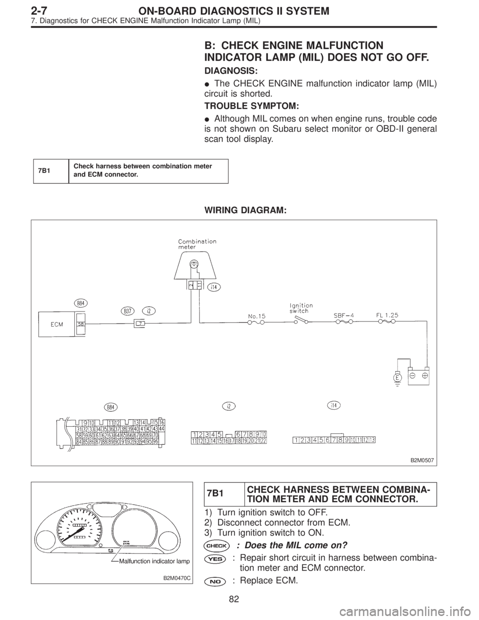
B: CHECK ENGINE MALFUNCTION
INDICATOR LAMP (MIL) DOES NOT GO OFF.
DIAGNOSIS:
�The CHECK ENGINE malfunction indicator lamp (MIL)
circuit is shorted.
TROUBLE SYMPTOM:
�Although MIL comes on when engine runs, trouble code
is not shown on Subaru select monitor or OBD-II general
scan tool display.
7B1Check harness between combination meter
and ECM connector.
WIRING DIAGRAM:
B2M0507
B2M0470C
7B1CHECK HARNESS BETWEEN COMBINA-
TION METER AND ECM CONNECTOR.
1) Turn ignition switch to OFF.
2) Disconnect connector from ECM.
3) Turn ignition switch to ON.
: Does the MIL come on?
: Repair short circuit in harness between combina-
tion meter and ECM connector.
: Replace ECM.
82
2-7ON-BOARD DIAGNOSTICS II SYSTEM
7. Diagnostics for CHECK ENGINE Malfunction Indicator Lamp (MIL)
Page 1851 of 2890
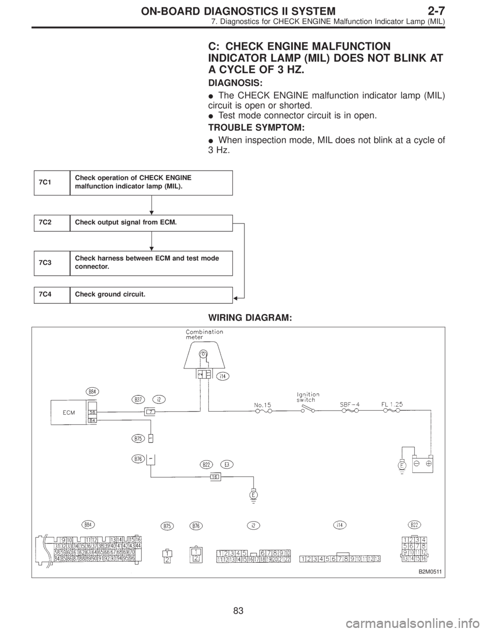
C: CHECK ENGINE MALFUNCTION
INDICATOR LAMP (MIL) DOES NOT BLINK AT
A CYCLE OF 3 HZ.
DIAGNOSIS:
�The CHECK ENGINE malfunction indicator lamp (MIL)
circuit is open or shorted.
�Test mode connector circuit is in open.
TROUBLE SYMPTOM:
�When inspection mode, MIL does not blink at a cycle of
3 Hz.
7C1Check operation of CHECK ENGINE
malfunction indicator lamp (MIL).
7C2Check output signal from ECM.
�
7C3Check harness between ECM and test mode
connector.
7C4Check ground circuit.
WIRING DIAGRAM:
B2M0511
�
�
83
2-7ON-BOARD DIAGNOSTICS II SYSTEM
7. Diagnostics for CHECK ENGINE Malfunction Indicator Lamp (MIL)
Page 1854 of 2890
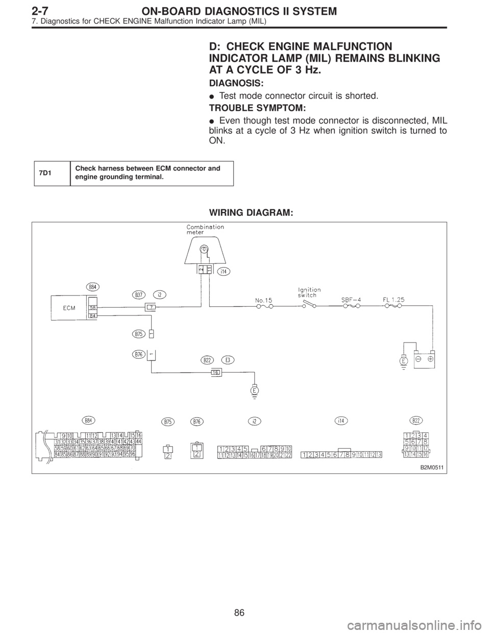
D: CHECK ENGINE MALFUNCTION
INDICATOR LAMP (MIL) REMAINS BLINKING
AT A CYCLE OF 3 Hz.
DIAGNOSIS:
�Test mode connector circuit is shorted.
TROUBLE SYMPTOM:
�Even though test mode connector is disconnected, MIL
blinks at a cycle of 3 Hz when ignition switch is turned to
ON.
7D1Check harness between ECM connector and
engine grounding terminal.
WIRING DIAGRAM:
B2M0511
86
2-7ON-BOARD DIAGNOSTICS II SYSTEM
7. Diagnostics for CHECK ENGINE Malfunction Indicator Lamp (MIL)
Page 1857 of 2890
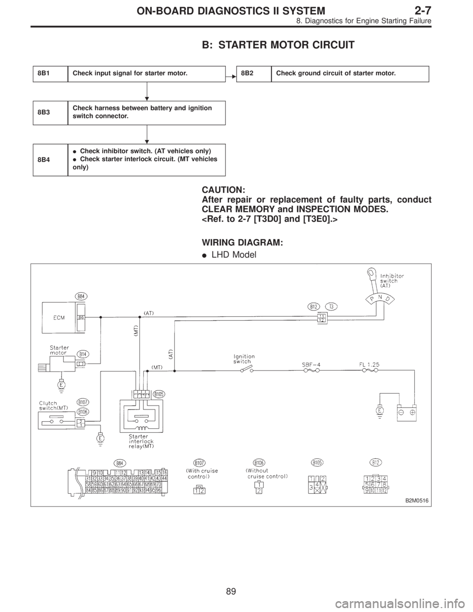
B: STARTER MOTOR CIRCUIT
8B1Check input signal for starter motor.�8B2Check ground circuit of starter motor.
8B3Check harness between battery and ignition
switch connector.
8B4
�Check inhibitor switch. (AT vehicles only)
�Check starter interlock circuit. (MT vehicles
only)
CAUTION:
After repair or replacement of faulty parts, conduct
CLEAR MEMORY and INSPECTION MODES.
WIRING DIAGRAM:
�LHD Model
B2M0516
�
�
89
2-7ON-BOARD DIAGNOSTICS II SYSTEM
8. Diagnostics for Engine Starting Failure