Page 1755 of 2890

E: DIAGNOSTICS PROCEDURE FOR
SECURITY CONTROL MODULE POWER
SUPPLY/GROUND CIRCUIT
1. Check fuse and power supply circuit.
OK
�Not OK
�Replace fuse.
�Repair or replace wiring harness.
2. Check ground circuit between security control
module and body.
OK
�Not OK
Repair or replace wiring harness.
Go to next step on basic diagnostics procedure.
B6M0504A
1. CHECK FUSE AND POWER SUPPLY CIRCUIT.
1) Check fuse No. 25.
2) Measure voltage between main fuse box connector and
body.
Connector & terminal / Specified voltage:
(F35) No. 2—Body / 10 V, or more
B6M0448A
3) Disconnect connector from security control module.
4) Measure voltage between security control module con-
nector and body.
Connector & terminal / Specified voltage:
(B93) No. 8—Body / 10 V, or more
B6M0505A
5) Check fuse No. 3.
6) Turn ignition switch to ACC.
7) Measure voltage between fuse and relay box connec-
tor and body.
Connector & terminal / Specified voltage:
(i5) No. 13—Body / 10 V, or more
�
�
91
6-2DIAGNOSTICS
6. Security System
Page 1757 of 2890

F: DIAGNOSTICS PROCEDURE FOR
SECURITY INDICATOR LIGHT AND
INDICATOR LIGHT CIRCUIT
1. Check security indicator light.
OK
�Not OK
Replace indicator light.
2. Check power supply for indicator light.
OK
�Not OK
Repair or replace wiring harness.
3. Check harness connector between security
indicator light and security control module.
OK
�Not OK
Repair or replace wiring harness.
Go to next step on basic diagnostics procedure.
B6M0382A
1. CHECK SECURITY INDICATOR LIGHT.
1) Remove security indicator light.
2) Measure resistance between security indicator light
connector terminals.
Terminals / Specified resistance:
No. 2—No. 4 / Approx. 120Ω
B6M0443A
2. CHECK POWER SUPPLY FOR INDICATOR LIGHT.
1) Disconnect connector of security indicator light.
2) Measure voltage between security indicator light con-
nector and body.
Connector & terminal / Specified voltage:
(i8) No. 2—Body / 10 V, or more
B6M0498A
3. CHECK HARNESS CONNECTOR BETWEEN
SECURITY INDICATOR LIGHT AND SECURITY
CONTROL MODULE.
1) Disconnect connectors of security indicator light and
security control module.
2) Measure resistance of harness connector between
security indicator light and security control module.
Connector & terminal / Specified resistance:
(i8) No. 4—(B93) No.7/10Ω, max.
�
�
�
93
6-2DIAGNOSTICS
6. Security System
Page 1758 of 2890
G: DIAGNOSTICS PROCEDURE FOR DOOR
SWITCH SIGNAL
1. Check door switch input signal for security
control module.
Not OK
�OK
Go to next step on basic diagnostics procedure.
2. Check door switch.
OK
�Not OK
Replace door switch.
Repair or replace wiring harness between door
switch and security control module.
B6M0453A
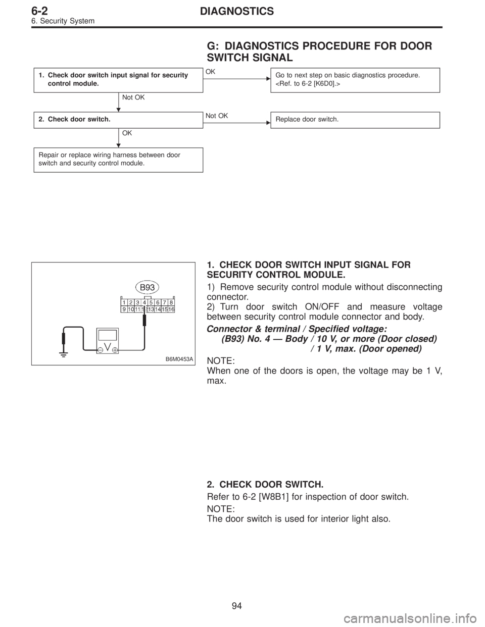
1. CHECK DOOR SWITCH INPUT SIGNAL FOR
SECURITY CONTROL MODULE.
1) Remove security control module without disconnecting
connector.
2) Turn door switch ON/OFF and measure voltage
between security control module connector and body.
Connector & terminal / Specified voltage:
(B93) No. 4—Body / 10 V, or more (Door closed)
/ 1 V, max. (Door opened)
NOTE:
When one of the doors is open, the voltage may be 1 V,
max.
2. CHECK DOOR SWITCH.
Refer to 6-2 [W8B1] for inspection of door switch.
NOTE:
The door switch is used for interior light also.
�
�
94
6-2DIAGNOSTICS
6. Security System
Page 1759 of 2890
H: DIAGNOSTICS PROCEDURE FOR ENGINE
HOOD SWITCH SIGNAL
1. Check engine hood switch input signal for
security control module.
Not OK
�OK
Go to next step on basic diagnostics procedure.
2. Check engine hood switch.
OK
�Not OK
Replace engine hood switch.
Repair or replace wiring harness between engine
hood switch and security control module.
B6M0451A
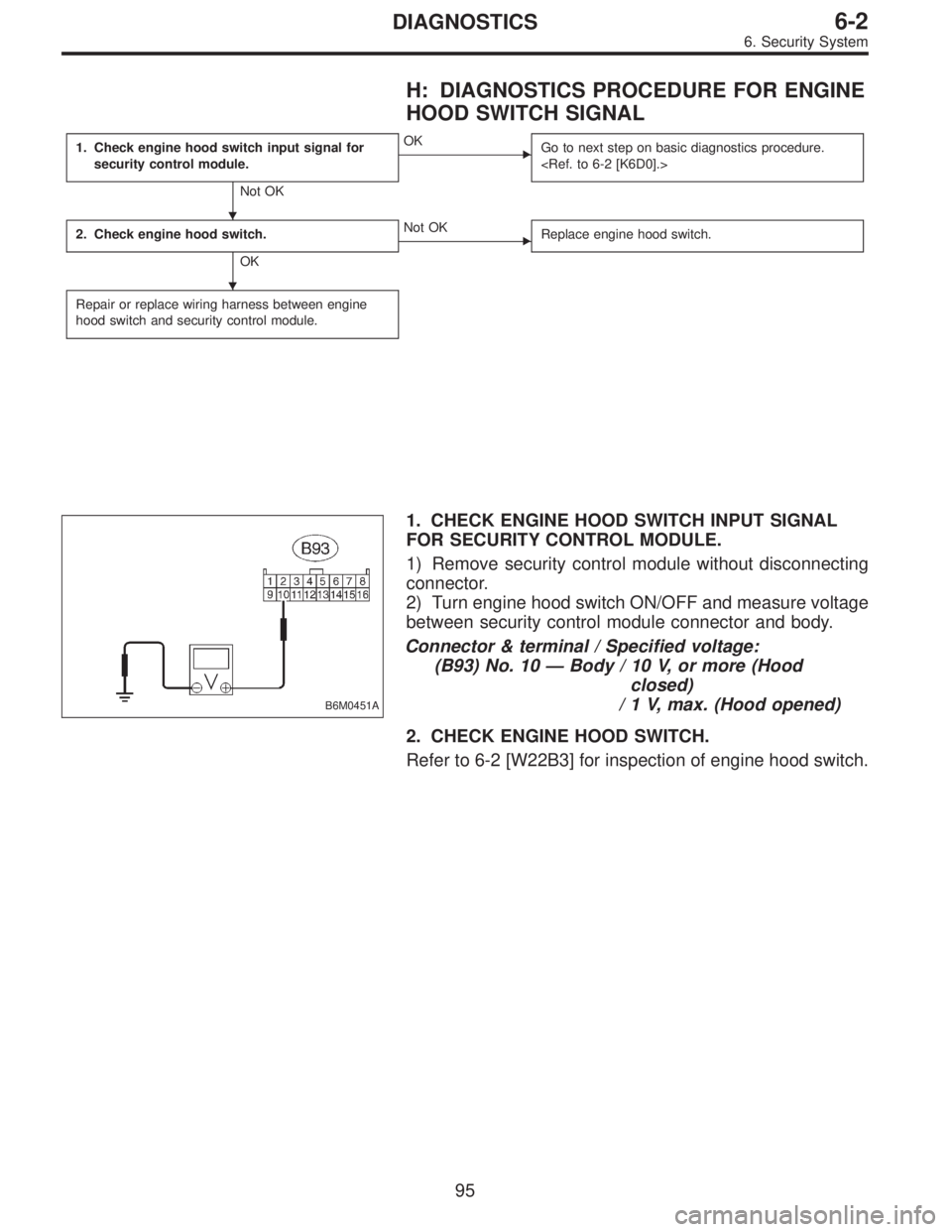
1. CHECK ENGINE HOOD SWITCH INPUT SIGNAL
FOR SECURITY CONTROL MODULE.
1) Remove security control module without disconnecting
connector.
2) Turn engine hood switch ON/OFF and measure voltage
between security control module connector and body.
Connector & terminal / Specified voltage:
(B93) No. 10—Body / 10 V, or more (Hood
closed)
/ 1 V, max. (Hood opened)
2. CHECK ENGINE HOOD SWITCH.
Refer to 6-2 [W22B3] for inspection of engine hood switch.
�
�
95
6-2DIAGNOSTICS
6. Security System
Page 1760 of 2890
 OR REAR GATE
SWITCH (WAGON) SIGNAL
1. Check trunk lid switch (SEDAN) or rear gate
switch (WAGON) input signal for security
control module.
Not OK")
I: DIAGNOSTICS PROCEDURE FOR TRUNK
LID SWITCH (SEDAN) OR REAR GATE
SWITCH (WAGON) SIGNAL
1. Check trunk lid switch (SEDAN) or rear gate
switch (WAGON) input signal for security
control module.
Not OK
�OK
Go to next step on basic diagnostics procedure.
2. Check trunk lid switch (SEDAN) or rear gate
switch (WAGON).
OK
�Not OK
Replace trunk lid switch (or rear gate switch).
Repair or replace wiring harness between trunk lid
switch (or rear gate switch) and security control
module.
B6M0450A
1. CHECK TRUNK LID SWITCH (SEDAN) OR REAR
GATE SWITCH (WAGON) INPUT SIGNAL FOR
SECURITY CONTROL MODULE.
1) Remove security control module without disconnecting
connector.
2) Turn trunk lid switch (or rear gate switch) ON/OFF and
measure voltage between security control module connec-
tor and body.
Connector & terminal / Specified voltage:
(B93) No. 11—Body / 10 V, or more
(Lid or gate closed)
/ 1 V, max.
(Lid or gate opened)
2. CHECK TRUNK LID SWITCH (SEDAN) OR REAR
GATE SWITCH (WAGON).
Refer to 6-2 [W8B2], [W8B3] for inspection of trunk lid
switch/rear gate switch.
NOTE:
The trunk lid switch/rear gate switch is used for both trunk
room light/luggage room light.
�
�
96
6-2DIAGNOSTICS
6. Security System
Page 1761 of 2890

J: DIAGNOSTICS PROCEDURE FOR DOOR
LOCK/UNLOCK SWITCH SIGNAL
1. Check door lock/unlock switch input signal
for security control module.
Not OK
�OK
Go to next step on basic diagnostics procedure.
2. Check door lock/unlock switch.
OK
�Not OK
Replace door lock/unlock switch.
Repair or replace wiring harness between door lock/
unlock switch and security control module.
B6M0407A
1. CHECK DOOR LOCK/UNLOCK SWITCH INPUT
SIGNAL FOR SECURITY CONTROL MODULE.
1) Remove security control module without disconnecting
connector.
2) Close all the doors and rear gate (WAGON), and lock
with ignition key.
3) Measure voltage between security control module con-
nector and body.
Connector & terminal / Specified voltage:
(B93) No. 1—Body / 10 V, or more
NOTE:
When one of the door (driver, passenger or rear gate) lock
knobs is in unlocked position, the voltage may be 1 V, max.
4) Unlock the door with ignition key.
5) Measure voltage between security control module con-
nector and body.
Connector & terminal / Specified voltage:
(B93) No. 1—Body/1V,max.
2. CHECK DOOR LOCK/UNLOCK SWITCH.
Refer to 6-2 [W22B5] for inspection of door lock/unlock
switch.
�
�
97
6-2DIAGNOSTICS
6. Security System
Page 1762 of 2890

K: DIAGNOSTICS PROCEDURE FOR KEY
CYLINDER LOCK/UNLOCK SWITCH AND
TAMPER SWITCH SIGNAL
NOTE:
Key cylinder lock switch, key cylinder unlock switch and
tamper switch are combined as a unit.
1. Check key cylinder switch input signal for
security control module.
Not OK
�OK
Go to next step on basic diagnostics procedure.
2. Check key cylinder switch.
OK
�Not OK
Replace key cylinder switch.
Repair or replace wiring harness between key
cylinder switch and security control module.
B6M0499A
1. CHECK KEY CYLINDER SWITCH INPUT SIGNAL
FOR SECURITY CONTROL MODULE.
1) Remove security control module without disconnecting
connector.
2) Measure voltage between security control module con-
nector and body while turning each key cylinder with igni-
tion key.
Doors (RH and LH), and rear gate (WAGON)
Connector & terminal / Specified voltage:
(B93) No. 2—Body/1V,max. (LOCK position)
/ 10 V, or more (other than
LOCK position)
B6M0447A
(B93) No. 14—Body/1V,max. (UNLOCK position)
/ 10 V, or more (other than
UNLOCK position)
�
�
98
6-2DIAGNOSTICS
6. Security System
Page 1764 of 2890

L: DIAGNOSTICS PROCEDURE FOR
STARTER INTERRUPT SIGNAL
1. Check starter interrupt output signal for security
control module.
Not OK
�OK
5. Check starter interrupt relay.
OK Not OK
Repair or replace
wiring harness of
starter motor circuit.
Replace starter
interrupt relay.
2. Check power supply for starter interrupt relay.
OK
�Not OK
Repair or replace wiring harness between starter
interrupt relay and battery.
3. Check continuity of starter interrupt relay.
OK
�Not OK
Replace starter interrupt relay.
4. Check harness connector between starter
interrupt relay and security control module.
OK
�Not OK
Repair or replace wiring harness between starter
interrupt relay and security control module.
Replace security control module.
B6M0445A
1. CHECK STARTER INTERRUPT OUTPUT SIGNAL
FOR SECURITY CONTROL MODULE.
1) Remove security control module without disconnecting
connector.
2) Measure voltage between security control module con-
nector and body.
Connector & terminal / Specified voltage:
(B93) No. 5—Body / 10 V, or more
3) Set security system in armed state.
4) Open the door without ignition key to operate the secu-
rity system (alarm state).
5) Measure voltage between security control module and
body during alarm state.
Connector & terminal / Specified voltage:
(B93) No. 5—Body/1V,max.
��
�
�
�
�
100
6-2DIAGNOSTICS
6. Security System