Page 189 of 2890

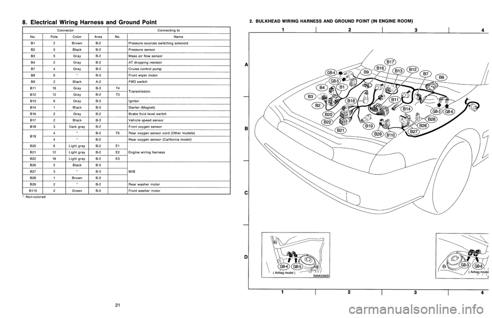
8
.
Electrical
Wiring
Harness
and
Ground
Point
Connector
Connecting
to
No
.
Pole
Color
Area
No
.
Name
131
2
Brown
B-2
Pressure
sources
switching
solenoid
B2
3
Black
B-2
Pressure
sensor
B3
5
Gray
B-2
Mass
air
slow
sensor
B4
2
Gray
B-2
AT
dropping
resistor
B7
4
Gray
B-3
Cruise
control
pump
B8
6B-3Front
wiper
motor
B9
2
Black
A-2
FWD
switch
B11
16
Gray
B-3
T4
T
B12
12
Gray
B-2
T3
ransmission
B13
6
Gray
B-3
Ignitor
B14
1
Black
B-3
Starter
(Magnet)
B16
2
Gray
B-2
Brake
fluid
level
switch
B17
2
Black
B-3
Vehicle
speed
sensor
B18
3
Dark
gray
B-2Front
oxygen
sensor
4B-2
T5Rear
oxygen
sensor
cord(Other
models)
B19
4B-2
Rear
oxygen
sensor
(California
model)
B20
6Light
gray
B-2El
821
12
Light
gray
B-2
E2Engine
wiring
harness
B22
16
Light
gray
B-2
E3
B26
2
Black
B-3
B27
3B-3
MIB
B28
1
Brown
B-3
B29
2B-2
Rear
washer
motor
B110
~
2
f
Green
B-3
~
Front
washer
motor
`
:
Non-colored
2
.
BULKHEAD
WIRING
HARNESS
AND
GROUND
POINT
(IN
ENGINE
ROOM)
1
2
3
a
E
C
DI
Yi-t
~
GB-4GB-5
(Air
`bag
model
(
Airbag
model
~rrE
1
23
4
21
Page 190 of 2890

r
Connecting
to
)r
Area
No
.
Name
C-4
D1
Front
doorcord
RH
ow
C-4
ABi
SRS
(Airbag)
harness
;k
C-4
Turn
&
hazard
module
.k
C-3
i1
C-3
i2
instrument
panel
wiring
un
C-3
i3
harness
e
C-3
i4
y
C-3
OBD-IIservice
connector
C-3
Power
window
circuit
breaker
C-3
Power
window
relay
;k
C-3
Illuminationcontrol
module
C-3
Seat
belt
timer
;n
B-4
Fuel
pump
relay
vn
B-4
Main
relay
;k
B-4
Horn
relay
B-4
Blower
relay
y
C-4
FIB
y
C-4
B-3
Shield
joint
connector
(AT)
.k
B-3
:k
B-3
Transmission
control
module
.k
B-3
:k
B-3
Shift-lock
control
module
B-4F44
i
h
B-4F45
Front
w
ring
arness
.k
B-3
Stop
light
switch
,k
B-3
Stop
8
brake
switch
(Withcruise
control)
:k
8-3
Cruise
control
sub
switch
Connector
Connecting
to
No
.
Pole
Color
Area
No
.
Name
869
11
Black
C-3
B70
9
C-3
Combination
switch
B71
8
8-3
B72
6
Black
C-3
Ignition
switch
B73
2
Black
B-3
Key
lock
solenoid
B74
2
Black
B-3
Key
warning
switch
B75
2
Green
B-2
876
T
d
B76
2
Green
8-2
875
e
connector
est
mo
877
7
B-2
Mode
actuator
B78
9
Yellow
B-2
Data
link
connector
B79
14
Gray
C-2
Check
connector
BBO
4
Blue
B-2
i20
Instrument
panel
wiring
harness
B81
1
x
2
B-2
Diagnosis
terminal
(Ground)
B82
6
Black
B-2
Diagnosisconnector
BB3
4
C-1
Shield
joint
connector
(EIG)
BBQ
96Lightblue
C-2
Engine
control
module
B85
4
Brown
B-3
Diode
(Lighting)
B86
4
Black
B-1
Blower
motor
resistor
887
2
Black
B-1
Blower
motor
888
3
Black
B-1
Evaporatorthermoswitch
B90
2
Green
B-4
R50
Room
light
cord
B91
5
B-1
FRESHIRECIRC
actuator
B92
8
B-1
Door
lock
timer
894
20
Black
B-1
Cruise
control
module
B97
56
B-4
R1
Rear
wiring
harness
(S.M
.J
.)
B101
24
B-1
D11
Front
door
cord
LH
8111
3
Gray
C-4FIB
`
:
Non-colored
4
.
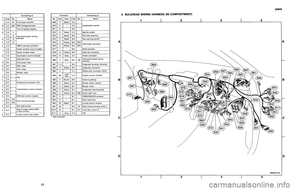
BULKHEAD
WIRING
HARNESS
(IN
COMPARTMENT)
1
I
2
I
3
I
4
A
B
C
D
1
I
2
I
3
I
4
[oeo41
B6M0513A
A
B
C
iJ
23
Page 191 of 2890

Connector
Connecting
to
No
.
Pole
Color
Area
No
.
Name
830
24
C-4
D1
Front
door
cord
RH
831
7
Yellow
C-4
A81
SRS
(Airbag)
harness
B32
3
Black
C-4
Turn
&
hazard
module
B36
22
Black
C-3
i1
B37
22
C-3
i2
Instrument
panel
wiring
B38
22
Brown
C-3
i3
harness
B39
20Blue
C-3
i4
B40
16
Gray
C-3
OBD-II
service
connector
B41
2
C-3
Power
window
circuit
breaker
842
4
C-3
Power
window
relay
B43
6
Black
C-3
Illumination
control
module
B44
8
C-3
Seat
belt
timer
B46
4
Green
B-4
Fuel
pump
relay
B47
6
Brown
B-4
Main
relay
B49
3
Black
B-4
Horn
relay
850
4
B-4
Blower
relay
851
11
Gray
C-4
FIB
B52
12
Gray
C-4
853
4
B-3
Shield
joint
connector
(AT)
B54
12
Black
B-3
B55
16
Black
B-3
Transmission
control
module
B56
20
Black
B-3
B57
12
Black
B-3
Shift-lock
control
module
861
B
B-4
F44
B62
20
B-4
F45
Front
wiring
harness
B64
2
Black
B-3
Stop
light
switch
B65
4
Black
B-3
Stop
&
brake
switch(Withcruise
control)
B68
5
i
Black
i
B-3
Cruise
control
sub
switch
Connector
Connecting
to
No
.
Pole
Color
Area
No
.
Name
B69
11
Black
C-3
B70
9
C-3
Combination
switch
B71
8
8-3
B72
6
Black
C-3
Ignition
switch
B73
2
Black
B-3
Key
lock
solenoid
B74
2
Black
B-3
Key
warning
switch
B75
2
Green
B-2
B76
B76
2
Green
&2
B75
Test
mode
connector
B77
7
B-2
Made
actuator
B78
9
Yellow
B-2
Data
link
connector
B79
14
Gray
C-2
Check
connector
B80
4
Blue
B-2
i20
Instrumentpanel
wiring
harness
B81
1
x
2
B-2
Diagnosis
terminal
(Ground)
B82
6
Black
B-2
Diagnosis
connector
B83
4
C-1
Shield
joint
connector
(E!G)
884
96
Light
blue
C-2
Engine
control
module
885
4
Brown
B-3
Diode
(Lighting)
B86
4
Black
B-1
Blower
motor
resistor
887
2
Black
B-1
Blower
motor
B88
3
Black
8-t
Evaporator
thermoswitch
890
2
Green
B-4
R50
Room
light
cord
B91
5B-1
FRESHIRECIRC
actuator
892
8
B-1
Door
lock
timer
B94
20
Black
B-1
Cruise
control
module
B97
56
B-4
R1Rear
wiring
harness
(S
.M
.J
.)
B101
24
B-1
D11
Front
doorcord
LH
13111
3
Gray
C-4
FIB
`
:
Non-colored
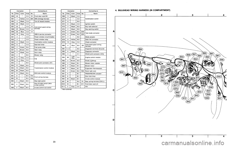
4
.
BULKHEAD
WIRING
HARNESS
(IN
COMPARTMENT)
A
B
C
1]
4
23
Page 216 of 2890
![SUBARU LEGACY 1996 Service Repair Manual
ON-BOARD
DIAGNOSTICS
II
SYSTEM
[rsi2]
2-7
8
.
Diagnostics
for
Engine
Starting
Failure
WIRING
DIAGRAM
:
Fuel
pump
M
R58
S
.M
.J
.
R67R46
R1
897
E
B84
ECM
Fuel
pump
relay
0
846
SBF-2
No
.1 SUBARU LEGACY 1996 Service Repair Manual
ON-BOARD
DIAGNOSTICS
II
SYSTEM
[rsi2]
2-7
8
.
Diagnostics
for
Engine
Starting
Failure
WIRING
DIAGRAM
:
Fuel
pump
M
R58
S
.M
.J
.
R67R46
R1
897
E
B84
ECM
Fuel
pump
relay
0
846
SBF-2
No
.1](/manual-img/17/57433/w960_57433-215.png)
ON-BOARD
DIAGNOSTICS
II
SYSTEM
[rsi2]
2-7
8
.
Diagnostics
for
Engine
Starting
Failure
WIRING
DIAGRAM
:
Fuel
pump
M
R58
S
.M
.J
.
R67R46
R1
897
E
B84
ECM
Fuel
pump
relay
0
846
SBF-2
No
.16
~b---
862F45
884
9
10
1112
13141516
R58
R61B46
3132
333435363738
39
40
4142
43
44585960
6162
6364
6566
6768
6910
1
2
3
~1
]
M34
1
84
1
8
51
86
1
871
88
1
89
1
90
1
91
1
92
1
93
1
94
1
95
1
96
1
4
56~J
82M
1014
PUMpK
OPERATING
SOUND
OFFUEL
811
CHEC
R58
OBD0132A
Make
sure
that
fuel
pump
isin
operation
for
two
seconds
when
turning
ignition
switch
to
ON
.
CHECK
:
Does
fuel
pump
produce
operating
sound?
NOTE
:
Fuel
pump
operation
check
can
also
beexecuted
using
Subaru
Select
Monitor
(Function
mode
:
FD01)
.
For
the
procedure,
referto
"COMPULSORY
VALVE
OPER-
ATION
CHECK
MODE"
2-7
[T3F0]*4
.
,res
:
Check
fuel
injector
circuit
.
<
Ref
.
to
2-7
[T10Q0].*2
>
No
:
Go
to
step
812
.
1
812
CHECK
GROUND
CIRCUIT
OF
FUEL
PUMP
.
1)
Turn
ignition
switch
to
OFF
.
2)
Disconnect
connector
from
fuel
pump
.
3)
Measure
resistance
of
harness
connector
between
fuel
pump
and
chassis
ground
.
CHECK
:
Connector
&
terminal
(R58)
No
.
4
-
Chassis
ground
:
Is
the
resistance
less
than
5
S2?
5
Page 222 of 2890
ON-BOARD
DIAGNOSTICS
II
SYSTEM
RIoBOOi
2-7
10
.
Diagnostics
Chart
with
Trouble
Code
WIRING
DIAGRAM
:
B84
ECM
(
,?22
9D
Q
IE
S
.M
.J
.
897
Rt
R15
R57
884
822
12
34
78
3
4
9
17118119120121122123124
25
261271281291301
1
A
?6
41147
52535455
56
57
9
01112
7
71
1
4
1
417576177
1
1
16
(~
Fueltank
:
:
:M[
:EjjFue1
temperature
ss
ensor
-M
FTM
r-,
.M
F112
3
RUSTUP
141516
B2M1015
11
Page 227 of 2890
2-7
[ryoaPO]
ON-BOARD
DIAGNOSTICS
II
SYSTEM
10
.
Diagnostics
Chart
with
Trouble
Code
OBD
(FBI)
P0181
H2M1350
BP
:
DTC
P0181
-
FUEL
TEMPERATURE
SENSOR
A
CIRCUIT
RANGE/PERFORMANCE
PROBLEM
(TN
KT
-
F)
-
DTC
DETECTINGCONDITION
:
Two
consecutive
trips
with
fault
10BP1
I
Check
DTC
P0180
on
display
.
CAUTION
:
After
repair
or
replacement
of
faultyparts,
conduct
CLEAR
MEMORY
and
INSPECTION
MODES
.
Ref
.
to
2-7
[T3D0]
and
[T3E0]
.*2
and
*4
>
WIRING
DIAGRAM
:
884
ECM
301
S
.M
.J
.
B91
R1
R15R57R58
Fuel
tank
Fuel
temperature
===@H
sensor
884B22
1
U34
U5U
78
U
1
2
34
1711811912012112212312
51
1152211523112152511526113'
68
55
91
1451461471481491501
47
1
01112
1/11/21/31141151761//1781/91601811821631
193142116
U
1121
E
1
23
4
1
b
1
65
3-7
10
1
[49
B2M1015
16
Page 230 of 2890
ON-BOARD
DIAGNOSTICS
II
SYSTEM
ITyoso2i
2-7
10
.
DiagnosticsChart
with
Trouble
Code
WIRING
DIAGRAM
:
Main
relay
0
0
847
884
77
ECM
V
897
R69
S
.M
.J
.
~°c~
Vent
control
solenoid
valve
R68
R57R15
Pressure
control
862F45
SBF-2
O~C)-
B
~E
822
O
E4
Purge
control
solenoid
valve
--{~J
solenoid
valve
B84R68
R69
R57847
822
E4
1
U
49
10
11
1
1314
1
16
1
234
171
1
811
9
12012112212
1113
63
1
36
44
444
M56
5678
49
1
63
55116
68
/Ul
1
3
9101112
9
19
~Lltu
~
4L_L51bIJ~l
13141516
B2M1017
10BQ1
I
CHECK
ANY
OTHER
DTC
(BESIDES
DTC
P0440)
ON
DISPLAY
.
Is
there
any
other
DTC
on
display?
Inspect
the
relevant
DTC
using
"10
.
Diagnostics
Chart
with
Trouble
Code,
2-7
[T10A0]"*7
.
No
:
Go
to
step
101302
.
FILLER
PIPE
.
FILLER
CAPAND
FUEL
1)
Turn
ignition
switch
to
OFF
.
2)
Open
the
fuelflap
.
CHECK
:
Is
the
fuel
filler
cap
tightened
securely?
Tighten
fuel
filler
cap
securely
.
o
:
Go
to
next
CHECK
.
19
Page 234 of 2890
ON-BOARD
DIAGNOSTICS
11
SYSTEM
[rIoBROi
2-7
10
.
Diagnostics
Chart
with
Trouble
Code
WIRING
DIAGRAM
:
Main
relay
0
0
B41
B61F45
SBF-2
B84
~
ECM
S
.M
.J
Vent
control
.
solenoid
897
Rt
R15
R57
R69
valve
Canister
O
B47R57
R69
U
910
U
1112
U
1314L11516
3132
3334353637383940
4142
4344
1
2
6162
63
64656667
68
6970
34
1
lu
//j848586
8788
8990
9192
93
949596
56
B2M1018
23