Page 1567 of 2890
B5M0026
7) Remove cover back panel.
G5M0278
8) Remove two bolts and lower steering column.
B5M0027
9) Set temperature control lever to Max. COLD position,
and then disconnect temperature control cable from link of
heater module.
NOTE:
Do not move lever and link when installing.
B5M0028
10) Remove bolt cover and bolt of both side.
B5M0029A
11) Remove front side sill cover RH and then disconnect
airbag connector (AB9) and (AB10) (Airbag model).
to 5-5 [M2-6].>
6
5-4SERVICE PROCEDURE
1. Instrument Panel
Page 1577 of 2890
.
�The designated trouble code is output during self-diag-
nosis. (Refer t")
6. COMBINATION SWITCH
Inspection standard:
�A vehicle damaged in a collision (regardless of whether
or not airbag is deployed).
�The designated trouble code is output during self-diag-
nosis. (Refer to“Diagnostics”Section.)
Replacement standard:
�Combination switch or steering roll connector is
deformed or cracked.
B5M0095
7. STEERING WHEEL
Inspection standard:
�A vehicle damaged in a collision (regardless of whether
or not airbag is deployed).
Replacement standard:
�Check steering wheel insert for cracks or deformities.
�Check to ensure that new airbag module is properly
installed in steering wheel.
�After installing airbag module, check to ensure that it is
free of interference with steering wheel and that clearance
between the two is equal at all points.
B5M0096A
8. STEERING COLUMN ASSEMBLY
Inspection standard:
�A vehicle damaged in a collision (regardless of whether
or not airbag is deployed).
Replacement standard:
�Check steering wheel free play in axial and radial direc-
tions.
Specifications:
Axial free play A
Less than ±6 mm (0.24 in)
Radial free play L
Less than ±7 mm (0.28 in)
8
5-5SERVICE PROCEDURE
2. Inspection and Replacement Standards
Page 1578 of 2890
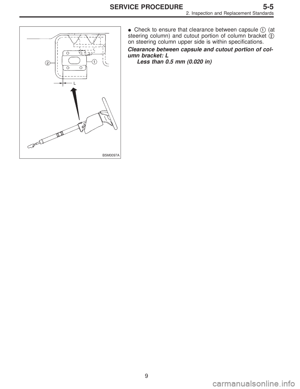
B5M0097A
�Check to ensure that clearance between capsule�1(at
steering column) and cutout portion of column bracket�
2
on steering column upper side is within specifications.
Clearance between capsule and cutout portion of col-
umn bracket: L
Less than 0.5 mm (0.020 in)
9
5-5SERVICE PROCEDURE
2. Inspection and Replacement Standards
Page 1584 of 2890
G5M0312
3) Remove lower cover.
Disconnect airbag connector (AB3) and (AB8) below steer-
ing column.
CAUTION:
Do not reconnect airbag connector at steering column
until front sensors are securely re-installed.
G5M0313
4) Remove console box. Discon-
nect 2-pin blue connector (AB4) (right side front sensor)
and 2-pin orange connector (AB5) (left side front sensor)
from airbag control module.
G5M0314
5) Roll up floor mat and side sill cover.
[W5A10].> Remove front sensor harness from clip and pro-
tector.
6) Remove front wheels.
7) Remove front mud guard.
G5M0315
8) Remove wiring harness clips.
G5M0316
9) Remove grommet.
14
5-5SERVICE PROCEDURE
4. Front Sensor
Page 1585 of 2890
B5M0102
10) Remove front sensor.
B: INSTALLATION
Installation is in reverse order of removal procedures.
5. Main Harness
A: REMOVAL
1) Turn ignition switch off.
2) Disconnect ground cable from battery and wait for at
least 20 seconds before starting work.
G5M0312
3) Remove lower cover.
Disconnect airbag connector (AB3) and (AB8) below steer-
ing column.
CAUTION:
Do not reconnect airbag connector at steering column
until main harness are securely re-installed.
G5M0313
4) Remove console box. Discon-
nect 12-pin yellow connector (AB6) from airbag control
module.
15
5-5SERVICE PROCEDURE
4. Front Sensor - 5. Main Harness
Page 1586 of 2890
B5M0102
10) Remove front sensor.
B: INSTALLATION
Installation is in reverse order of removal procedures.
5. Main Harness
A: REMOVAL
1) Turn ignition switch off.
2) Disconnect ground cable from battery and wait for at
least 20 seconds before starting work.
G5M0312
3) Remove lower cover.
Disconnect airbag connector (AB3) and (AB8) below steer-
ing column.
CAUTION:
Do not reconnect airbag connector at steering column
until main harness are securely re-installed.
G5M0313
4) Remove console box. Discon-
nect 12-pin yellow connector (AB6) from airbag control
module.
15
5-5SERVICE PROCEDURE
4. Front Sensor - 5. Main Harness
Page 1589 of 2890
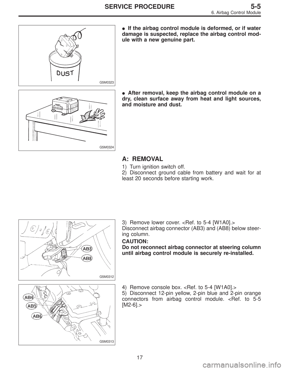
G5M0323
�If the airbag control module is deformed, or if water
damage is suspected, replace the airbag control mod-
ule with a new genuine part.
G5M0324
�After removal, keep the airbag control module on a
dry, clean surface away from heat and light sources,
and moisture and dust.
A: REMOVAL
1) Turn ignition switch off.
2) Disconnect ground cable from battery and wait for at
least 20 seconds before starting work.
G5M0312
3) Remove lower cover.
Disconnect airbag connector (AB3) and (AB8) below steer-
ing column.
CAUTION:
Do not reconnect airbag connector at steering column
until airbag control module is securely re-installed.
G5M0313
4) Remove console box.
5) Disconnect 12-pin yellow, 2-pin blue and 2-pin orange
connectors from airbag control module.
[M2-6].>
17
5-5SERVICE PROCEDURE
6. Airbag Control Module
Page 1590 of 2890
 Using TORX®BIT T40 (Tamper resistant type), remove
two TORX®bolts.
Discard the old TORX®bolts.
CAUTION:
Use new TORX
®bolts during re-assembly.
B: INSTALLATION
Installation is in revers")
B5M0105
6) Using TORX®BIT T40 (Tamper resistant type), remove
two TORX®bolts.
Discard the old TORX®bolts.
CAUTION:
Use new TORX
®bolts during re-assembly.
B: INSTALLATION
Installation is in reverse order of removal procedures.
CAUTION:
Be sure to fully secure all airbag system connectors
during re-assembly and confirm that all green double
lock mechanisms are engaged.
7. Combination Switch
A: REMOVAL
1) Turn ignition switch off.
2) Disconnect ground cable from battery and wait for at
least 20 seconds before starting work.
G5M0312
3) Remove lower cover. Disconnect
airbag connector (AB3) and (AB8) below steering column.
CAUTION:
Do not reconnect airbag connector at steering column
until combination switch is securely re-installed.
4) Disconnect combination switch connectors from body
harness connector.
H5M0662A
5) Set front wheels in straight ahead position. Using
TORX®BIT T30, remove two TORX®bolts.
18
5-5SERVICE PROCEDURE
6. Airbag Control Module - 7. Combination Switch
 Remove cover back panel.
G5M0278
8) Remove two bolts and lower steering column.
B5M0027
9) Set temperature control lever to Max. COLD position,
and then disconnect temperature control cable")
![SUBARU LEGACY 1996 Service Repair Manual G5M0312
3) Remove lower cover. <Ref. to 5-4 [W1A0].>
Disconnect airbag connector (AB3) and (AB8) below steer-
ing column.
CAUTION:
Do not reconnect airbag connector at steering column
until front sens](/manual-img/17/57433/w960_57433-1583.png "SUBARU LEGACY 1996 Service Repair Manual G5M0312
3) Remove lower cover. <Ref. to 5-4 [W1A0].>
Disconnect airbag connector (AB3) and (AB8) below steer-
ing column.
CAUTION:
Do not reconnect airbag connector at steering column
until front sens")
 Remove front sensor.
B: INSTALLATION
Installation is in reverse order of removal procedures.
5. Main Harness
A: REMOVAL
1) Turn ignition switch off.
2) Disconnect ground cable from battery")
 Remove front sensor.
B: INSTALLATION
Installation is in reverse order of removal procedures.
5. Main Harness
A: REMOVAL
1) Turn ignition switch off.
2) Disconnect ground cable from battery")