Page 1205 of 2890
8. CLEARANCE TABLE (RHD MODEL)
CAUTION:
This table lists various clearances that must be cor-
rectly adjusted to ensure normal vehicle driving with-
out interfering noise, or any other faults.
LocationMinimum
allowance
mm (in)LocationMinimum
allowance
mm (in)
�
1Crossmember—Pipe5 (0.20)�5Stabilizer—Pipe5 (0.20)
�
2DOJ—Shaft or joint14 (0.55)�6Exhaust pipe—Pipe15 (0.59)
�
3DOJ—Valve housing11 (0.43)�7Exhaust pipe—Gearbox boot15 (0.59)
�
4Pipe—Pipe
2 (0.08)�
8Side frame—Hose A and B15 (0.59)
Pipe—Crossmember�9Pipe portion of hose A—Pipe portion of hose B1.5
(0.059)
B4M0676A
98
4-3DIAGNOSTICS
1. Power Steering
Page 1206 of 2890

9. BREAKAGE OF HOSES
Pressure hose burstExcessive holding time of relief
statusInstruct customers.
Malfunction of relief valveReplace oil pump.
Poor cold characteristic of fluidReplace fluid.
Forced out return hosePoor connectionCorrect.
Poor holding of clipRetighten.
Poor cold characteristic of fluidReplace fluid.
Fluid bleeding out of hose slightlyWrong layout, tensionedReplace hose.
Excessive play of engine due to
deterioration of engine mounting
rubberReplace defective parts.
Improper stop position of pitching
stopperReplace defective parts.
*11
Crack on hose
Excessive holding time of relief
statusReplace.
Instruct customer.
Excessive tightening torque for
return hose clipReplace.
Power steering fluid, brake fluid,
engine oil, electrolyte adhere on
the hose surfaceReplace.
Pay attention on service work.
Too many times use in extremely
cold weatherReplace.
Instruct customers.
*11 Although surface layer materials of rubber hoses have excellent weathering resistance, heat resistance and resistance for
low temperature brittleness, they are likely to be damaged chemically by brake fluid, battery electrolyte, engine oil and
automatic transmission fluid and their service lives are to be very shortened. It is very important to keep the hoses free
from before mentioned fluids and to wipe out immediately when the hoses are adhered with the fluids.
Since resistances for heat or low temperature brittleness are gradually declining according to time accumulation of hot or
cold conditions for the hoses and their service lives are shortening accordingly, it is necessary to perform careful inspec-
tion frequently when the vehicle is used in hot weather areas, cold weather area and/or a driving condition in which many
steering operations are required in short time. Particularly continuous work of relief valve over 5 seconds causes to reduce
service lives of the hoses, the oil pump, the fluid, etc. due to over heat.
So, avoid to keep this kind of condition when servicing as well as driving.
99
4-3DIAGNOSTICS
1. Power Steering
Page 1270 of 2890

5) Perform these steps for the brakes connecting to the
secondary chamber of master cylinder, first, and then for
the ones con")
Air bleeder tightening torque:
8±1 N⋅m (0.8±0.1 kg-m, 5.8±0.7 ft-lb)
5) Perform these steps for the brakes connecting to the
secondary chamber of master cylinder, first, and then for
the ones connecting to primary chamber. With all proce-
dures completed, fully depress the brake pedal and keep
it in that position for approximately 20 seconds to make
sure that there is no leak evident in the entire system.
G4M0436
6) Perform sequence control. (With ABS model)
4-4 [W15C1].>
7) Check the pedal stroke.
While the engine is idling, depress the brake pedal with a
490 N (50 kg, 110 lb) load and measure the distance
between the brake pedal and steering wheel. With the
brake pedal released, measure the distance between the
pedal and steering wheel again. The difference between
the two measurements must be more than specified.
Specified pedal stroke:
Without ABS
90 mm (3.54 in)
With ABS
95 mm (3.74 in)
When depressing brake pedal with a 490 N (50 kg,
110 lb) load.
(1) Models without ABS
If the distance is more than specifications, there is a
possibility that air is in the brake line. Bleed air from the
brake line.
(2) Models with ABS
If the distance is more than specifications, there is a
possibility air is in the inside of the hydraulic unit.
Therefore, air must be bled from the inside of the
hydraulic unit to the brake pipes in accordance with the
bleeding sequence control.
8) Add brake fluid to the required level (MAX. level) of
reserve tank.
9) As a final step, test run the vehicle at low speed and
apply brakes relatively hard 2 to 3 times to ensure that
brakes provide normal braking action on all four wheels
without dragging and uneven braking.
63
4-4SERVICE PROCEDURE
11. Air Bleeding (Without TCS model)
Page 1298 of 2890
 Check the pedal stroke.
While the engine is idling, depress the brake pedal with a
490 N (50 kg, 110 lb) load and measure the distance
between the brake pedal and steering wheel. With the")
G4M0436
16) Check the pedal stroke.
While the engine is idling, depress the brake pedal with a
490 N (50 kg, 110 lb) load and measure the distance
between the brake pedal and steering wheel. With the
brake pedal released, measure the distance between the
pedal and steering wheel again. The difference between
the two measurements must be less than specified.
Specified pedal stroke:
With TCS
95 mm (3.74 in)
When depressing brake pedal with a 490 N (50 kg,
110 lb) load.
If the distance is more than specifications, there is a
possibility that air is in the brake line. Bleed air from the
brake line.
17) Turn ignition switch OFF.
18) Disconnect select monitor or diagnosis terminal.
19) Add brake fluid to the required level (MAX. level) of
reserve tank.
20) As a final step, test run the vehicle at low speed and
apply brakes relatively hard 2 to 3 times to ensure that
brakes provide normal braking action on all four wheels
without dragging and uneven braking.
2. CONDITIONS FOR AIR BLEEDING CONTROL
Stop light
switchTCS OFF
switchPump
motorTCS
valveFRO
RLOFLO
RROTCS
operating
indicator
lightABS
warning
lightTCS
warning
light
Air
bleeding
control is
operating.OFF ON ON Close Close Close ON ON ON
ON ON OFF Open Open Close ON ON OFF
ON ON OFF Open Close Open ON OFF ON
ON or OFF OFF OFF Open Close Close ON OFF OFF
Stops tem-
porarily.*——OFF Open Close Close OFF OFF OFF
Prohibited.——OFF Open Close Close OFF ON ON
*: When brake fluid level switch detects brake fluid in LOW level, control operation stops temporarily. After refilling brake fluid, operation
re-starts.
89
4-4SERVICE PROCEDURE
19. Air Bleeding (With TCS model)
Page 1364 of 2890
1. Supplemental Restraint System
“Airbag”
Airbag system wiring harness is routed near the instrument
panel, heater unit, blower motor and control unit.
CAUTION:
�All Airbag system wiring harness and connectors
are colored yellow. Do not use electrical test equip-
ment on these circuit.
�Be careful not to damage Airbag system wiring har-
ness when servicing the instrument panel, heater unit,
blower motor and control unit.
2. Heater Unit
A: REMOVAL AND INSTALLATION
1) Disconnect GND cable from battery.
2) Remove heater hoses (inlet, outlet) in engine compart-
ment.
NOTE:
Drain as much coolant from heater unit as possible, and
plug disconnected hose with cloth.
3) Remove instrument panel.
4) Remove steering support beam.
5) Remove evaporator. (With A/C model)
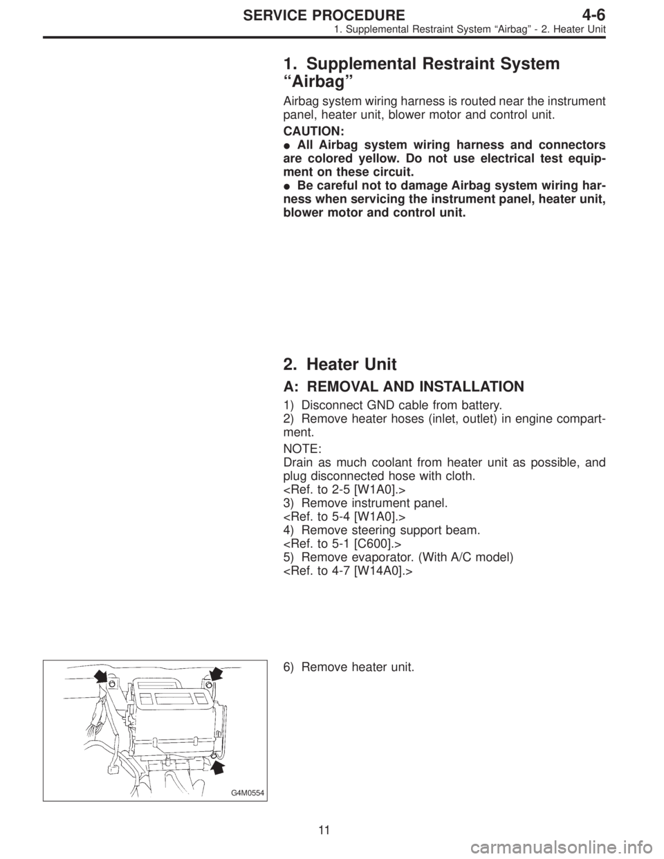
G4M0554
6) Remove heater unit.
11
4-6SERVICE PROCEDURE
1. Supplemental Restraint System“Airbag”- 2. Heater Unit
Page 1365 of 2890
1. Supplemental Restraint System
“Airbag”
Airbag system wiring harness is routed near the instrument
panel, heater unit, blower motor and control unit.
CAUTION:
�All Airbag system wiring harness and connectors
are colored yellow. Do not use electrical test equip-
ment on these circuit.
�Be careful not to damage Airbag system wiring har-
ness when servicing the instrument panel, heater unit,
blower motor and control unit.
2. Heater Unit
A: REMOVAL AND INSTALLATION
1) Disconnect GND cable from battery.
2) Remove heater hoses (inlet, outlet) in engine compart-
ment.
NOTE:
Drain as much coolant from heater unit as possible, and
plug disconnected hose with cloth.
3) Remove instrument panel.
4) Remove steering support beam.
5) Remove evaporator. (With A/C model)
G4M0554
6) Remove heater unit.
11
4-6SERVICE PROCEDURE
1. Supplemental Restraint System“Airbag”- 2. Heater Unit
Page 1407 of 2890
 Connect compressor harness.
3) Connect alternator harness.
4) Install compressor V-belt (Rear).
After adjusting belt tension, tighten tension pulley lock nut
securely.
G4M0632
5) Install alternator")
2) Connect compressor harness.
3) Connect alternator harness.
4) Install compressor V-belt (Rear).
After adjusting belt tension, tighten tension pulley lock nut
securely.
G4M0632
5) Install alternator V-belt.
After adjusting V-belt tension, tighten alternator bracket
lock bolt securely.
6) Check drive belt tension and adjust it if necessary by
changing alternator position and/or idler pulley position.
Pulley arrangement Tension mm (in)/98N (10 kg, 22 lb)
G4M0939
AB
*New belt:
7.0—9.0
(0.276—0.354)
Existing belt:
9.0—11.0
(0.354—0.433)*New belt:
7.5—8.5
(0.295—0.335)
Existing belt:
9.0—10.0
(0.354—0.394)
* When replacing belts with new ones, adjust tensions to
specification and then readjust to the same specification
after running engine for 5 minutes.
Figures in table refer to the number of grooves in pulleys.
C/P : Crankshaft pulley
ALT : Alternator pulley
P/S : Power steering oil pump pulley
A/C : Air conditioner compressor pulley
I/P : Idler pulley
33
4-7SERVICE PROCEDURE
11. Compressor
Page 1458 of 2890
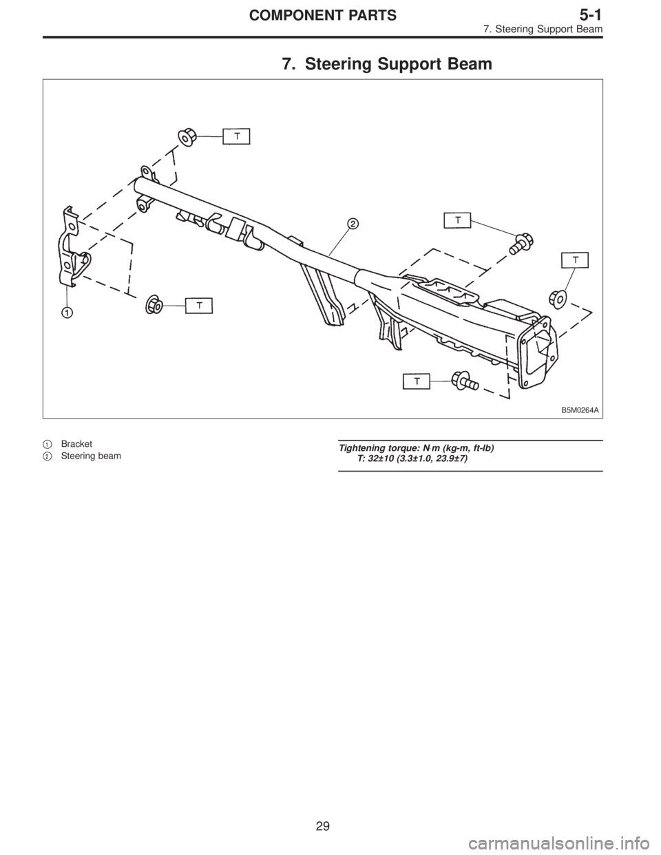
7. Steering Support Beam
B5M0264A
�1Bracket
�
2Steering beamTightening torque: N⋅m (kg-m, ft-lb)
T: 32±10 (3.3±1.0, 23.9±7)
29
5-1COMPONENT PARTS
7. Steering Support Beam

CAUTION:
This table lists various clearances that must be cor-
rectly adjusted to ensure normal vehicle driving with-
out interfering noise, or any other faults.
Locatio")