Page 1181 of 2890
C: DISASSEMBLY
B4M0142A
�1Pulley
�
2Snap ring
�
3Bearing
�
4Oil seal
�
5Shaft
�
6Connector
�
7O-ring
�
8Spool valve�
9Spring
�
10Front casing
�
11Rear cover
�
12Knock pin
�
13Seal washer
�
14Cam ring
�
15Vane
�
16Rotor�
17Side plate
Tightening torque: N⋅m (kg-m, ft-lb)
T1: 16±2 (1.6±0.2, 11.6±1.4)
T2: 61±7 (6.2±0.7, 45.0±5.2)
T3: 74±5 (7.5±0.5, 54.2±3.6)
B4M0561A
1) Oil pump body
(1) Place oil pump in a vise, and remove two bolts
which secure tank.
CAUTION:
Do not place oil pump directly in vise; use soft pads
and hold oil pump lightly to protect it.
74
4-3SERVICE PROCEDURE
9. Oil Pump (Power Steering System)
Page 1182 of 2890
G4M0178
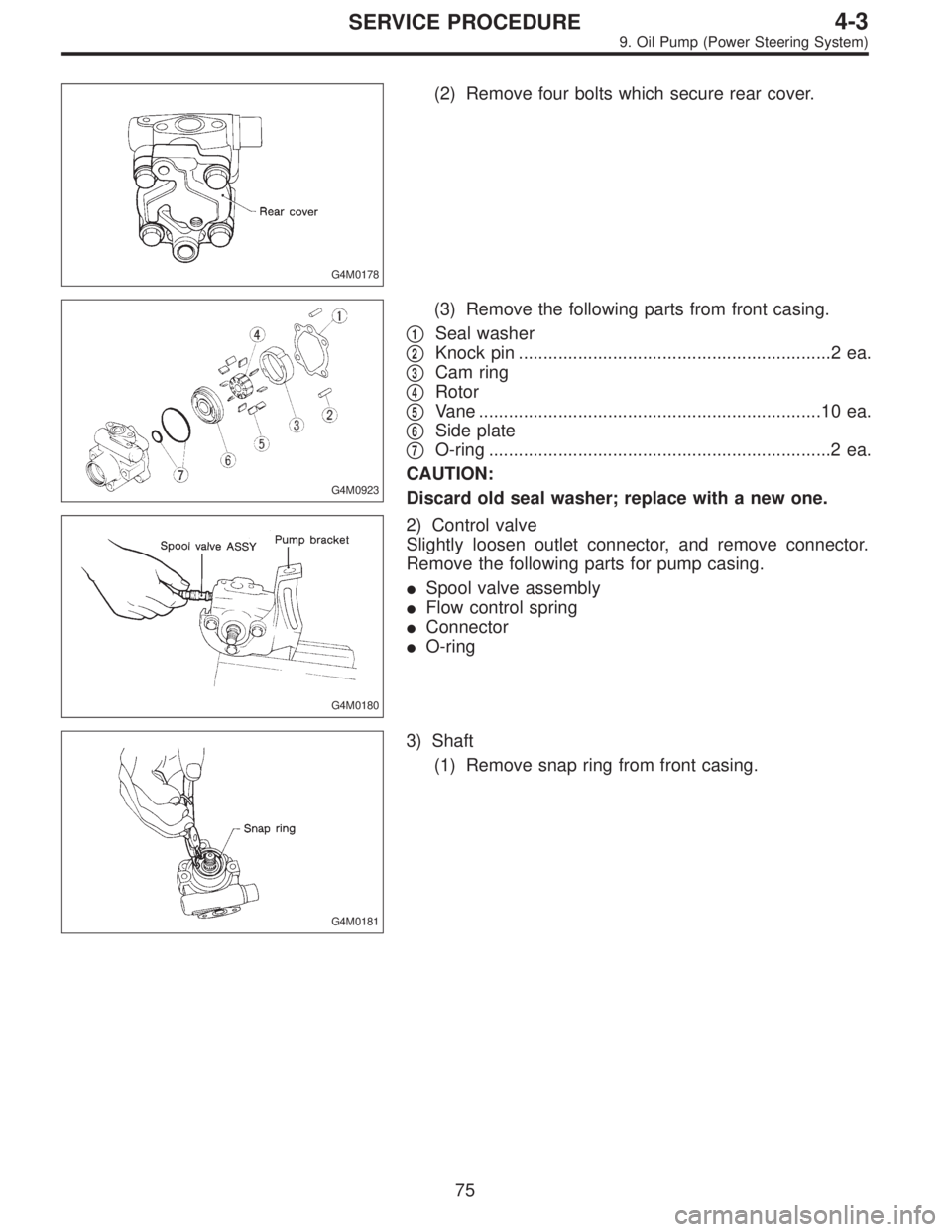
(2) Remove four bolts which secure rear cover.
G4M0923
(3) Remove the following parts from front casing.
�
1Seal washer
�
2Knock pin ...............................................................2 ea.
�
3Cam ring
�
4Rotor
�
5Vane .....................................................................10 ea.
�
6Side plate
�
7O-ring .....................................................................2 ea.
CAUTION:
Discard old seal washer; replace with a new one.
G4M0180
2) Control valve
Slightly loosen outlet connector, and remove connector.
Remove the following parts for pump casing.
�Spool valve assembly
�Flow control spring
�Connector
�O-ring
G4M0181
3) Shaft
(1) Remove snap ring from front casing.
75
4-3SERVICE PROCEDURE
9. Oil Pump (Power Steering System)
Page 1183 of 2890
 Remove shaft using a hand press.
CAUTION:
�Discard old drive shaft assembly; replace with a new
one.
�Be careful not to scratch or dent casing’s surface
which serves as a seal.
G4M0183
(")
G4M0182
(2) Remove shaft using a hand press.
CAUTION:
�Discard old drive shaft assembly; replace with a new
one.
�Be careful not to scratch or dent casing’s surface
which serves as a seal.
G4M0183
(3) Pry oil seal off using a screwdriver.
CAUTION:
Be careful not to scratch inner surface of casing.
4) Remove pressure switch.
D: INSPECTION
Perform the following inspection procedures and repair or
replace defective parts.
Part name Description Remedy
1. Front casing1) Damage on body surfaces
2) Excessive wear on hole, into which spool valve
is inserted.
3) Wear and damage on cartridge assembly mount-
ing surface
4) Wear and damage on surfaces in contact with
shaft and oil sealReplace with a new one together with spool valve
as selective fit is made.
2. Rear cover1) Damage on body surfaces
2) Wear and damage on sliding surfacesReplace with a new one.
3. Shaft1) Shaft bend
2) Wear and damage on surfaces in contact with
bushing and oil seal
3) Wear and damage on rotor mounting surfaces
4) Bearing damageReplace with a new one.
4. Side plate Wear and damage on sliding surfaces Replace with a new one.
5. Cam ring Ridge wear on sliding surfaces
If damage is serious, replace with a new cartridge
assembly. 6. Vane Excessive wear on nose radius and side surfaces
7. Rotor1) Wear and damage on sliding surfaces
2) Ridge wear on vane sliding grooves (If light
leaks with vane in slit against light source)
3) Damage resulting from snap ring removalCorrect with oil stone. If damage is serious, replace
with a new cartridge assembly.
8. Spool valve Damage or burrs on sliding surface peripheryReplace with a new one together with front casing
as selective fit is made.
9. Connector Damage on threads Replace with a new one.
10. Spring Damage Replace with a new one.
11. Bolts and nuts Damage on threads Replace with a new one.
76
4-3SERVICE PROCEDURE
9. Oil Pump (Power Steering System)
Page 1184 of 2890
 Reassembly precautions
(1) Whenever O-rings, oil seals, and snap rings are
removed, they must be replaced with new ones.
(2) Thoroughly wash parts and allow to dry. They must
be kept fr")
E: ASSEMBLY
1) Reassembly precautions
(1) Whenever O-rings, oil seals, and snap rings are
removed, they must be replaced with new ones.
(2) Thoroughly wash parts and allow to dry. They must
be kept free from cleaning oil and dust.
(3) Reassembly procedure must be performed in clean
place. Ensure that parts are kept away from waste
threads or other dust particles.
(4) Cleaning oil tends to stay inside the front casing.
Remove it completely by blowing compressed air.
(5) Ensure that parts are free from rust. (Use specified
hydraulic oil for rust prevention after cleaning and dry-
ing.)
(6) Reverse the sequence of disassembly procedures.
2) Shaft
(1) Apply grease to oil seal and inner surface of front
casing (at bearing location).
CAUTION:
Make sure that the front body internal surfaces are free
from damage.
G4M0184
(2) Using ST, press-fit oil seal into front body.
ST 340099AA000 INSTALLER
CAUTION:
When press-fitting, use care to prevent damage to sur-
face mating with rear body.
NOTE:
Orient oil seal toward correct direction.
G4M0185
(3) Using ST, press-fit shaft assembly into front body
and mount snap ring.
ST 340099AA020 INSTALLER
NOTE:
Turn snap ring to ensure that it fits right into the groove.
77
4-3SERVICE PROCEDURE
9. Oil Pump (Power Steering System)
Page 1185 of 2890
 Cartridge assembly
(1) Apply specified hydraulic oil to O-rings and fit them
into front casing.
(2) Install side plate to front casing.
CAUTION:
Use care not to let side plate gall.
G4M0187")
G4M0186
3) Cartridge assembly
(1) Apply specified hydraulic oil to O-rings and fit them
into front casing.
(2) Install side plate to front casing.
CAUTION:
Use care not to let side plate gall.
G4M0187
(3) Mount rotor onto shaft.
(4) Install 10 vanes into rotor with their nose radius
facing toward cam ring.
(5) Install cam ring to front casing, securing with knock
pins.
CAUTION:
Do not use hammer to fit knock pins in position.
G4M0188
4) Rear cover
(1) Mount seal washer on front casing.
(2) With knock pin positions aligned, install rear cover.
Tightening torque:
16±2 N⋅m (1.6±0.2 kg-m, 11.6±1.4 ft-lb)
CAUTION:
Loosely tighten bolts in the sequence�
1,�3,�2, and�4
shown in figure. Then, tighten in the same sequence.
G4M0189
5) Spool Valve
(1) Install spring into front casing. Then, with spool
valve dipped in specified hydraulic oil, install it into the
front casing.
(2) Using a 5-mm dia. round bar, ensure that valve
moves smoothly.
(3) Set O-ring, with grease applied to it, onto connec-
tor and secure connector to front casing.
Tightening torque:
74±5 N⋅m (7.5±0.5 kg-m, 54.2±3.6 ft-lb)
CAUTION:
�Use care to prevent damage to O-ring at installation.
�When tightening connector, ensure that O-ring does
not protrude or get caught.
78
4-3SERVICE PROCEDURE
9. Oil Pump (Power Steering System)
Page 1186 of 2890
 Check
(1) When reassembly procedures have been
completed, turn shaft by hand to ensure it turns
smoothly. If it binds or other unusual conditions are
evident, disassemble again and check for foreig")
6) Check
(1) When reassembly procedures have been
completed, turn shaft by hand to ensure it turns
smoothly. If it binds or other unusual conditions are
evident, disassemble again and check for foreign mat-
ter trapped on sliding surfaces and improper installa-
tion. Eliminate the cause of trouble.
(2) Check followings by referring to“CHECK”article.
�Excessive play in pulley shaft
�Ditch deflection of pulley
�Resistance to rotation of pulley
�Measurement of generated oil pressure
F: INSTALLATION
1) Install bracket on engine.
Tightening torque:
22±2 N⋅m (2.2±0.2 kg-m, 15.9±1.4 ft-lb)
2) Install oil pump on oil tank as follows outside the
vehicle:
NOTE:
Prior to installation, make sure that all oil is removed from
oil pump, oil tank and pipe.
B4M0562A
3) Place oil pump in vise.
CAUTION:
Do not place oil pump directly in vise; use soft pads
and hold oil pump lightly to protect it.
4) Install oil tank on oil pump.
Tightening torque:
Bolt C: 15.7±2.4 N⋅m
(1.60±0.24 kg-m, 11.58±1.77 ft-lb)
Bolt D: 18.1±2.5 N⋅m
(1.85±0.25 kg-m, 13.35±1.84 ft-lb)
CAUTION:
Discard old seal washer and replace with a new one.
79
4-3SERVICE PROCEDURE
9. Oil Pump (Power Steering System)
Page 1187 of 2890
B4M0560
5) Install oil pump, previously assembled to oil tank, on
bracket.
Tightening torque:
20.1±2.5 N⋅m (2.05±0.25 kg-m, 14.8±1.8 ft-lb)
6) Place oil pump pulley and tighten pulley nut temporarily.
B4M0556A
7) Interconnect pipes C and D.
Tightening torque:
Joint nut
15±5 N⋅m (1.5±0.5 kg-m, 10.8±3.6 ft-lb)
CAUTION:
If a hose is twisted at this step, the hose may come into
contact with some other parts.
8) Install pulley belt to oil pump.
9) Tighten oil pump pulley nut to the specified torque.
Tightening torque:
61±7 N⋅m (6.2±0.7 kg-m, 44.8±5.1 ft-lb)
10) Adjust pulley belt tension.
11) Tighten bolt belt tension.
Tightening torque:
8±2 N⋅m (0.8±0.2 kg-m, 5.8±1.4 ft-lb)
12) Install pulley belt cover bracket.
13) Connect minus terminal of battery.
14) Feed the specified fluid and discharge air.
NOTE:
Never start the engine before feeding the fluid; otherwise
vane pump might be seized up.
80
4-3SERVICE PROCEDURE
9. Oil Pump (Power Steering System)
Page 1188 of 2890
 Fee")
10. Power Steering Fluid
A: RECOMMENDED AIR BLEEDING AND
POWER STEERING FLUID
Recommended power steering fluid Manufacturer
ATF DEXRON II or ATF DEXRON IIEB.P.
CALTEX
CASTROL
MOBIL
SHELL
TEXACO
1) Feed the specified fluid with its level being about 5 cm
(2.0 in) lower than the mouth of tank.
2) Continue to turn steering wheel slowly from lock to lock
until bubbles stop appearing in the tank while keeping the
fluid at that level.
3) In case air is absorbed to deliver bubbles into piping
because the fluid level is lower, leave it about half an hour
and then do the step 2) all over again.
4) Start, and idle the engine.
5) Continue to turn steering wheel slowly from lock to lock
again until bubbles stop appearing in the tank while keep-
ing the fluid at that level.
It is normal that bubbles stop appearing after three times
turning of steering wheel.
6) In case bubbles do not stop appearing in the tank, leave
it about half an hour and then do the step 5) all over again.
7) Stop the engine, and take out safety stands after jack-
ing up vehicle again.
Then lower the vehicle, and idle the engine.
8) Continue to turn steering wheel from lock to lock until
bubbles stop appearing and change of the fluid level is
within 3 mm (0.12 in).
9) In case the following happens, leave it about half an
hour and then do step 8) again.
(1) The fluid level changes over 3 mm (0.12 in).
(2) Bubbles remain on the upper surface of the fluid.
(3) Grinding noise is generated from oil pump.
81
4-3SERVICE PROCEDURE
10. Power Steering Fluid

 Install oil pump, previously assembled to oil tank, on
bracket.
Tightening torque:
20.1±2.5 N⋅m (2.05±0.25 kg-m, 14.8±1.8 ft-lb)
6) Place oil pump pulley and tighten pulley nut tempora")