Page 1149 of 2890
G4M0137
B: DISASSEMBLY
1. VALVE ASSEMBLY
1) Loosen two bolts securing valve assembly.
G4M0138
2) Carefully draw out input shaft and remove valve assem-
bly.
G4M0139
3) Draw out pinion and valve assembly from valve
housing, as necessary, using pipe of I.D. 44 to 46 mm (1.73
to 1.81 in) and a press.
G4M0140
2. RACK ASSEMBLY
1) Slide mounting rubber to expose slit.
G4M0141
2) Rotate rack stopper in the direction of arrow using ST
until the end of circlip comes out of stopper, then rotate it
in the opposite direction, and pull out circlip.
ST 926340001 WRENCH
42
4-3SERVICE PROCEDURE
5. Control Valve (Power Steering Gearbox) [LHD model]
Page 1150 of 2890
G4M0142
NOTE:
If ST is used, grind area (shown in figure) by 1 mm (0.04
in) in advance.
ST 926340000 WRENCH
G4M0143
3) Pull rack assembly from cylinder side, and draw out
rack bushing and rack stopper together with rack assem-
bly.
CAUTION:
Be careful not to contact rack to inner wall of cylinder
when drawing out. Any scratch on cylinder inner wall
will cause oil leakage.
4) Remove rack bushing and rack stopper from rack
assembly.
CAUTION:
Do not reuse removed rack bushing and circlip.
G4M0144
C: REPLACEMENT OF SEAL AND PACKING
1. VALVE HOUSING OIL SEAL
�Removal
1) Pry off dust seal using screwdriver.
2) Remove snap ring using snap ring pliers.
G4M0145
3) Pry off oil seal using screwdriver.
CAUTION:
After removing, check inside surface of valve housing
for damage. If oil seal contacting surface is damaged,
replace valve housing with a new one.
43
4-3SERVICE PROCEDURE
5. Control Valve (Power Steering Gearbox) [LHD model]
Page 1151 of 2890
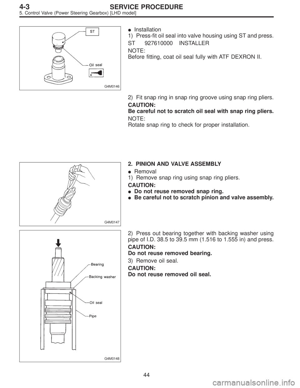
G4M0146
�Installation
1) Press-fit oil seal into valve housing using ST and press.
ST 927610000 INSTALLER
NOTE:
Before fitting, coat oil seal fully with ATF DEXRON II.
2) Fit snap ring in snap ring groove using snap ring pliers.
CAUTION:
Be careful not to scratch oil seal with snap ring pliers.
NOTE:
Rotate snap ring to check for proper installation.
G4M0147
2. PINION AND VALVE ASSEMBLY
�Removal
1) Remove snap ring using snap ring pliers.
CAUTION:
�Do not reuse removed snap ring.
�Be careful not to scratch pinion and valve assembly.
G4M0148
2) Press out bearing together with backing washer using
pipe of I.D. 38.5 to 39.5 mm (1.516 to 1.555 in) and press.
CAUTION:
Do not reuse removed bearing.
3) Remove oil seal.
CAUTION:
Do not reuse removed oil seal.
44
4-3SERVICE PROCEDURE
5. Control Valve (Power Steering Gearbox) [LHD model]
Page 1152 of 2890
 Fit pinion and valve assembly into valve housing.
NOTE:
Apply ATF DEXRON II to outer diameter surface of input
shaft and outer surface of valve body seal ring, and pay
special attenti")
�Installation
1) Fit pinion and valve assembly into valve housing.
NOTE:
Apply ATF DEXRON II to outer diameter surface of input
shaft and outer surface of valve body seal ring, and pay
special attention not to damage seal when inserting pinion
and valve assembly.
G4M0149
2) Secure valve assembly to ST1 and ST2.
3) Put ST3 over pinion, and insert oil seal, then force-fit oil
seal into housing using ST4.
NOTE:
�Apply ATF DEXRON II to oil seal and ST3, being care-
ful not to damage oil seal lip.
�Push oil seal until ST3 contacts housing end face.
4) Remove ST3, and fit backing washer.
ST1 926370000 INSTALLER A
ST2 927630000 STAND BASE
ST3 926360000 INSTALLER A
ST4 927620000 INSTALLER B
G4M0150
5) Force-fit ball bearing using ST3.
ST1 926370000 INSTALLER A
ST2 927630000 STAND BASE
ST3 927640000 INSTALLER B
NOTE:
Be careful not to tilt ball bearing during installation.
6) Install snap ring using snap ring pliers.
NOTE:
Rotate snap ring to check for proper installation.
G4M0151
3. RACK HOUSING OIL SEAL AND BACK-UP
WASHER
�Removal
Insert a round rod [26—27 mm (1.02—1.06 in) dia.] from
pinion housing side and remove oil seal and back-up
washer by hammering the rod.
NOTE:
�Discard removed oil seal and back-up washer.
�Apply the unchamfered end of remover to back-up
washer.
45
4-3SERVICE PROCEDURE
5. Control Valve (Power Steering Gearbox) [LHD model]
Page 1153 of 2890

G4M0152
�Installation
Force-fit oil seal and back-up washer using ST.
ST 927650000 INSTALLER
CAUTION:
Be careful not to damage or scratch cylinder inner
wall.
NOTE:
�Apply ATF DEXRON II to oil seal.
�Pay special attention not to install back-up washer and
oil seal in wrong direction.
�Push oil seal until the stepped portion of A contacts end
face of B.
B4M0134A
D: ASSEMBLY
1. RACK ASSEMBLY
1) Fixing rack housing
Fix rack housing in vice using ST.
ST 926200000 STAND
CAUTION:
�When fixing rack housing in vice, be sure to use this
special tool. Do not fix rack housing in vice using pad
such as aluminum plates, etc.
�When using old rack housing, be sure to clean and
remove rust before assembling. Check pinion housing
bushing carefully.
G4M0154
2) Fit ST over toothed portion of rack assembly, and check
for binding or unsmooth insertion. If any deformation is
noted on flats at the end of rack, shape by using file, and
wash with cleaning fluid.
3) Apply genuine grease to teeth of thoroughly washed
rack assembly, and fit ST over the toothed portion.
ST 926390001 COVER & REMOVER
NOTE:
�Be careful not to block air passage with grease. Remove
excessive grease.
46
4-3SERVICE PROCEDURE
5. Control Valve (Power Steering Gearbox) [LHD model]
Page 1154 of 2890

�After fitting cover, check air passage hole for clogging.
If clogged, open by removing grease from the hole.
�Check rack shaft for damage.
�Apply ATF DEXRON II to this ST and surface of piston
ring to prevent seal from being damaged.
G4M0155
4) Insert rack assembly into rack housing from cylinder
side, and remove ST after it has passed completely
through oil seal.
NOTE:
Before inserting rack assembly, apply a coat of ATF
DEXRON II to surfaces of ST and rack piston.
ST 926390001 COVER & REMOVER
G4M0156
5) Fit ST1 and ST2 over the end of rack, and install rack
bushing.
ST1 926400000 GUIDE
ST2 927660000 GUIDE
CAUTION:
�If burrs, or nicks are found on this guide and rack
shaft portion, remove by filing.
�Dip rack bushing in ATF DEXRON II before installing,
and pay attention not to damage O-ring and oil seal.
G4M0157
6) Insert rack stopper into cylinder tube until internal
groove (on cylinder side) is aligned with external groove
(on rack stopper). Turn rack stopper with ST so that rack
stopper hole is seen through cylinder slits.
7) Insert rack stopper into rack housing, and wrap circlip
using ST to secure rack stopper in position.
ST 926340001 WRENCH
CAUTION:
Be careful not to scratch rack while winding circlip.
NOTE:
Rotate wrench another 90 to 180°after the end of circlip
has been wrapped in.
8) Fit mounting rubber onto rack housing.
47
4-3SERVICE PROCEDURE
5. Control Valve (Power Steering Gearbox) [LHD model]
Page 1155 of 2890
G4M0158
2. VALVE ASSEMBLY
1) Apply genuine grease to pinion gear and bearing of
valve assembly.
B4M0135
2) Install packing on valve assembly. Insert valve assem-
bly into place while facing rack teeth toward pinion.
CAUTION:
Be sure to use a new packing.
NOTE:
Do not allow packing to be caught when installing valve
assembly.
3) Tighten bolts alternately to secure valve assembly.
Tightening torque:
25±5 N⋅m (2.5±0.5 kg-m, 18.1±3.6 ft-lb)
CAUTION:
Be sure to alternately tighten bolts.
48
4-3SERVICE PROCEDURE
5. Control Valve (Power Steering Gearbox) [LHD model]
Page 1156 of 2890
![SUBARU LEGACY 1996 Service Repair Manual 6. Control Valve (Power Steering
Gearbox) [RHD model]
NOTE:
This section focuses on the disassembly and reassembly
of control valve. For the inspection and adjustment and the
service procedures for as](/manual-img/17/57433/w960_57433-1155.png "SUBARU LEGACY 1996 Service Repair Manual 6. Control Valve (Power Steering
Gearbox) [RHD model]
NOTE:
This section focuses on the disassembly and reassembly
of control valve. For the inspection and adjustment and the
service procedures for as")
6. Control Valve (Power Steering
Gearbox) [RHD model]
NOTE:
This section focuses on the disassembly and reassembly
of control valve. For the inspection and adjustment and the
service procedures for associated parts, refer to“Steering
Gearbox”.
B4M0668A
A: CHECKING OIL LEAKING POINTS
1. OIL LEAKING POINTS
1) If leak point is other than a, b, c, or d, perform check
step 5) in 4-3 [W6A2] before dismounting gearbox from
vehicle. If gearbox is dismounted without confirming where
the leak is, it must be mounted again to locate the leak
point.
2) Even if the location of the leak can be easily found by
observing the leaking condition, it is necessary to thor-
oughly remove the oil from the suspected portion and turn
the steering wheel from lock to lock about 30 to 40 times
with engine running, then make comparison of the sus-
pected portion between immediately after and several
hours after this operation.
3) Before starting oil leak repair work, be sure to clean the
gearbox, hoses, pipes, and surrounding parts. After com-
pleting repair work, clean these areas again.
49
4-3SERVICE PROCEDURE
6. Control Valve (Power Steering Gearbox) [RHD model]
 Loosen two bolts securing valve assembly.
G4M0138
2) Carefully draw out input shaft and remove valve assem-
bly.
G4M0139
3) Draw out pinion and valve assemb")
 by 1 mm (0.04
in) in advance.
ST 926340000 WRENCH
G4M0143
3) Pull rack assembly from cylinder side, and draw out
rack bushing and rack stopper")
 Apply genuine grease to pinion gear and bearing of
valve assembly.
B4M0135
2) Install packing on valve assembly. Insert valve assem-
bly into place while facing rack teeth")