Page 2476 of 2890

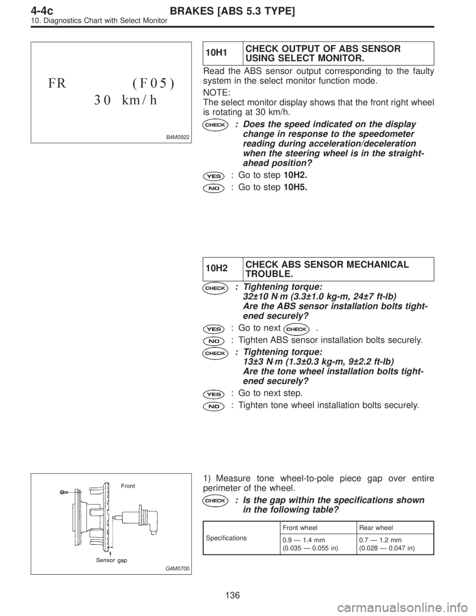
B4M0922
10H1CHECK OUTPUT OF ABS SENSOR
USING SELECT MONITOR.
Read the ABS sensor output corresponding to the faulty
system in the select monitor function mode.
NOTE:
The select monitor display shows that the front right wheel
is rotating at 30 km/h.
: Does the speed indicated on the display
change in response to the speedometer
reading during acceleration/deceleration
when the steering wheel is in the straight-
ahead position?
: Go to step10H2.
: Go to step10H5.
10H2CHECK ABS SENSOR MECHANICAL
TROUBLE.
: Tightening torque:
32±10 N⋅m (3.3±1.0 kg-m, 24±7 ft-lb)
Are the ABS sensor installation bolts tight-
ened securely?
: Go to next.
: Tighten ABS sensor installation bolts securely.
: Tightening torque:
13±3 N⋅m (1.3±0.3 kg-m, 9±2.2 ft-lb)
Are the tone wheel installation bolts tight-
ened securely?
: Go to next step.
: Tighten tone wheel installation bolts securely.
G4M0700
1) Measure tone wheel-to-pole piece gap over entire
perimeter of the wheel.
: Is the gap within the specifications shown
in the following table?
SpecificationsFront wheel Rear wheel
0.9—1.4 mm
(0.035—0.055 in)0.7—1.2 mm
(0.028—0.047 in)
136
4-4cBRAKES [ABS 5.3 TYPE]
10. Diagnostics Chart with Select Monitor
Page 2485 of 2890

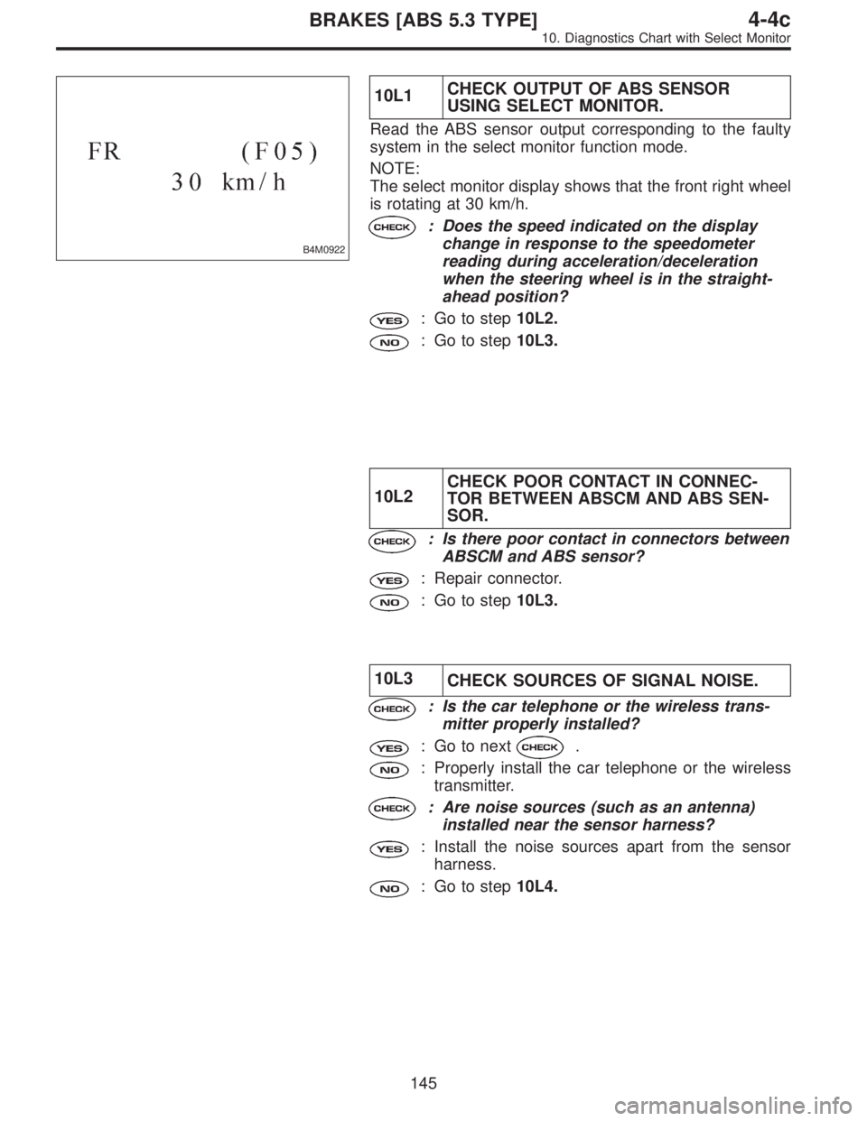
B4M0922
10L1CHECK OUTPUT OF ABS SENSOR
USING SELECT MONITOR.
Read the ABS sensor output corresponding to the faulty
system in the select monitor function mode.
NOTE:
The select monitor display shows that the front right wheel
is rotating at 30 km/h.
: Does the speed indicated on the display
change in response to the speedometer
reading during acceleration/deceleration
when the steering wheel is in the straight-
ahead position?
: Go to step10L2.
: Go to step10L3.
10L2CHECK POOR CONTACT IN CONNEC-
TOR BETWEEN ABSCM AND ABS SEN-
SOR.
: Is there poor contact in connectors between
ABSCM and ABS sensor?
: Repair connector.
: Go to step10L3.
10L3
CHECK SOURCES OF SIGNAL NOISE.
: Is the car telephone or the wireless trans-
mitter properly installed?
: Go to next.
: Properly install the car telephone or the wireless
transmitter.
: Are noise sources (such as an antenna)
installed near the sensor harness?
: Install the noise sources apart from the sensor
harness.
: Go to step10L4.
145
4-4cBRAKES [ABS 5.3 TYPE]
10. Diagnostics Chart with Select Monitor
Page 2494 of 2890
WIRING DIAGRAM:
B4M1035
10M1CHECK IF THE WHEELS HAVE TURNED
FREELY FOR A LONG TIME.
: Check if the wheels have been turned freely
for more than one minute, such as when the
vehicle is jacked-up, under full-lock corner-
ing or when tire is not in contact with road
surface.
: The ABS is normal. Erase the trouble code.
NOTE:
When the wheels turn freely for a long time, such as when
the vehicle is towed or jacked-up, or when steering wheel
is continuously turned all the way, this trouble code may
sometimes occur.
: Go to step10M2.
154
4-4cBRAKES [ABS 5.3 TYPE]
10. Diagnostics Chart with Select Monitor
Page 2632 of 2890

E: TROUBLE CODE 12
DIAGNOSIS:
�Airbag main harness circuit is open.
�Airbag module harness (Driver) circuit is open.
�Roll connector circuit is open.
�Airbag control module is faulty.
1. Airbag main harness inspection
O.K.
�Not O.K.
Replace airbag main harness.
Replace airbag control module.
CAUTION:
Before performing diagnostics on airbag system, turn
ignition switch“OFF”, disconnect battery ground
cable and then wait at least 20 seconds.
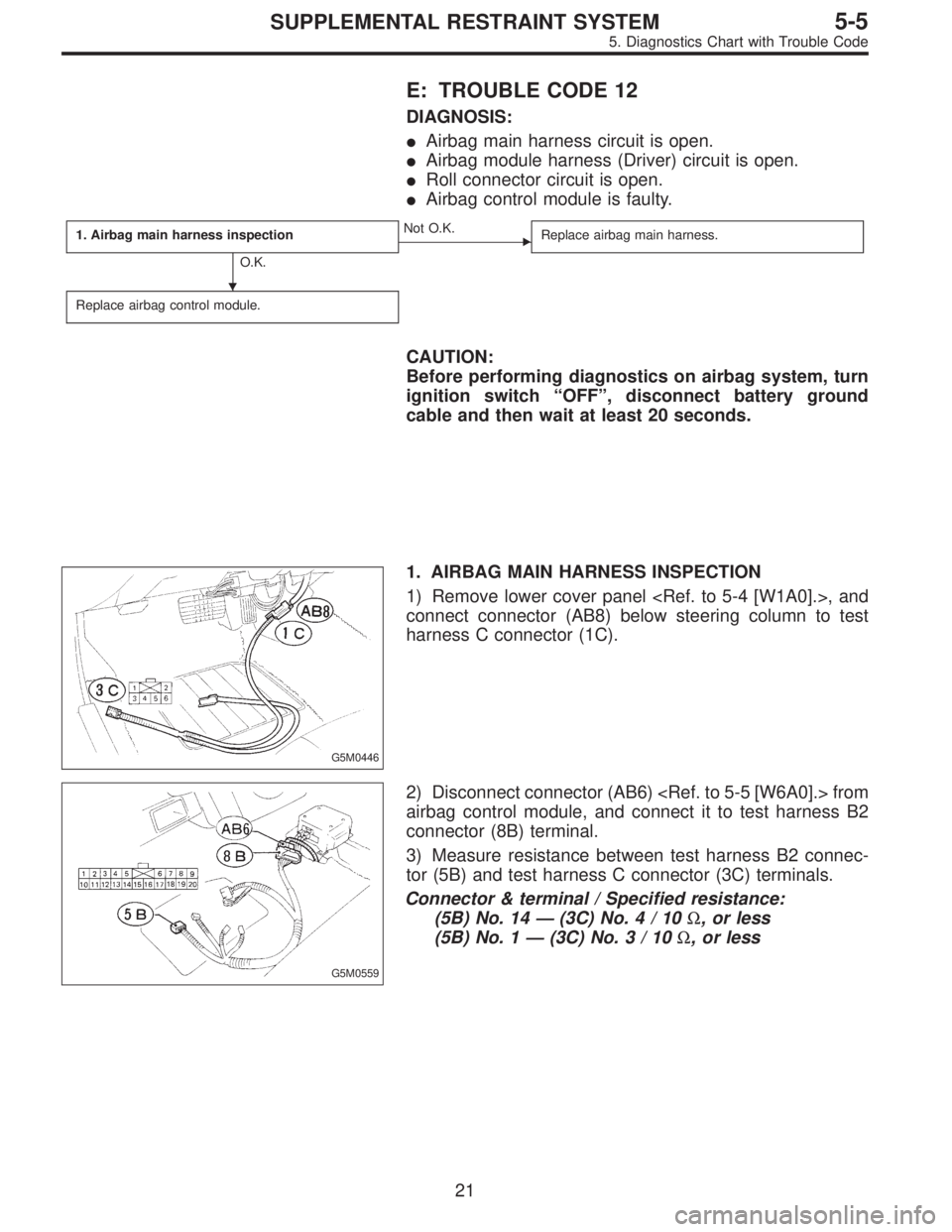
G5M0446
1. AIRBAG MAIN HARNESS INSPECTION
1) Remove lower cover panel , and
connect connector (AB8) below steering column to test
harness C connector (1C).
G5M0559
2) Disconnect connector (AB6) from
airbag control module, and connect it to test harness B2
connector (8B) terminal.
3) Measure resistance between test harness B2 connec-
tor (5B) and test harness C connector (3C) terminals.
Connector & terminal / Specified resistance:
(5B) No. 14—(3C) No.4/10Ω, or less
(5B) No. 1—(3C) No.3/10Ω, or less
�
21
5-5SUPPLEMENTAL RESTRAINT SYSTEM
5. Diagnostics Chart with Trouble Code
Page 2635 of 2890
B5M0029A
1. DOUBLE LOCK INSPECTION FOR CONNECTORS
(AB9) AND (AB10)
1) Remove front pillar lower trim (Passenger side).
to 5-3 [W5A1].>
2) Check double lock of connectors (AB9) and (AB10).
G5M0449
2. AIRBAG CONTROL MODULE DOUBLE LOCK
INSPECTION AT CONNECTORS (AB4) (AB5) (AB6)
Check double lock of connectors (AB4) (AB5) (AB6) con-
nected to airbag control module.
G5M0312
3. DOUBLE LOCK INSPECTION FOR CONNECTORS
(AB3) AND (AB8)
1) Remove lower cover panel.
2) Check double lock of connectors (AB3) and (AB8)
below steering column.
G5M0308
4. ROLL CONNECTOR DOUBLE LOCK INSPECTION
AT CONNECTORS (AB2) AND (AB7)
Remove driver side airbag module ,
and check double lock of connectors (AB2) and (AB7) at
roll connector.
24
5-5SUPPLEMENTAL RESTRAINT SYSTEM
5. Diagnostics Chart with Trouble Code
Page 2641 of 2890
G5M0446
1. AIRBAG MAIN HARNESS INSPECTION
1) Remove lower cover panel , and
connect connector (AB8) below steering column to test
harness C connector (1C).
G5M0559
2) Disconnect connector (AB6) from
airbag control module, and connect it to test harness B2
connector (8B) terminal.
3) Measure resistance between test harness B2 connec-
tor (5B) and test harness C connector (3C) terminals.
Connector & terminal / Specified resistance:
(5B) No. 14—(3C) No.4/10Ω, or less
(5B) No. 1—(3C) No.3/10Ω, or less
30
5-5SUPPLEMENTAL RESTRAINT SYSTEM
5. Diagnostics Chart with Trouble Code
Page 2650 of 2890
B5M0122B
3. AIRBAG WARNING LIGHT MODULE (IN
COMBINATION METER) INSPECTION
1) Turn ignition switch“OFF”, disconnect battery ground
cable and then wait at least 20 seconds.
2) Disconnect body harness connector (B31) from connec-
tor (AB1).
B5M0124A
3) Connect battery ground cable and turn ignition switch
“ON”(engine off) to make sure airbag warning light illumi-
nates.
If it does not, replace airbag warning light module�
1.
G5M0312
4. AIRBAG MAIN HARNESS INSPECTION
1) Turn ignition switch“OFF”, disconnect battery ground
cable and then wait at least 20 seconds.
2) Connect body harness connector (B31) and connector
(AB1).
3) Disconnect connectors (AB3) and (AB8) below steering
column.
G5M0313
4) Disconnect connector (AB6) from airbag control mod-
ule.
5) Connect battery ground cable and turn ignition switch
“ON”to make sure airbag warning light illuminates.
39
5-5SUPPLEMENTAL RESTRAINT SYSTEM
5. Diagnostics Chart with Trouble Code
Page 2653 of 2890
2. AIRBAG COMPONENT PARTS APPEARANCE
INSPECTION
Conduct appearance inspection on parts selected.
NOTE:
Also check connector terminals, wiring harness, case, etc.
for damage.
3. AIRBAG COMPONENT PARTS VIBRATION
INSPECTION
1) Gently shake check parts (to determine faults.).
2) To check airbag module or roll connector, turn and tilt
steering wheel.
CAUTION:
Do not shake or vibrate airbag control module and
front sensor at the same time as erroneous operation
may result.
G5M0461
4. SHOWERING INSPECTION TO BODY
1) Spray water on vehicle body.
CAUTION:
Do not directly spray water on airbag components.
2) Check passenger compartment for traces of leaking.
NOTE:
Also check wiring harnesses as water may leak along them
and get airbag component parts wet.
42
5-5SUPPLEMENTAL RESTRAINT SYSTEM
5. Diagnostics Chart with Trouble Code