Page 2003 of 2890

10AF1CHECK ANY OTHER DTC P0130, P0133,
P0135, P0136, P0139 AND P0141 ON DIS-
PLAY.
: Does the Subaru select monitor or OBD-II
general scan tool indicate DTC P0130,
P0133, P0135, P0136, P0139 and P0141?
: Inspect the relevant DTC using“10. Diagnostics
Chart with Trouble Code 2-7 [T1000]”.
NOTE:
In this case, it is not necessary to inspect DTC P0420.
: Go to step10AF2.
10AF2
CHECK EXHAUST SYSTEM.
Check for gas leaks or air suction caused by loose or dis-
located nuts and bolts, and open hole at exhaust pipes.
: Is there a fault in exhaust system?
NOTE:
Check the following positions.
�Between cylinder head and front exhaust pipe
�Between front exhaust pipe and front catalytic converter
�Between front catalytic converter and rear catalytic con-
verter
: Repair or replace exhaust system.
: Go to step10AF3.
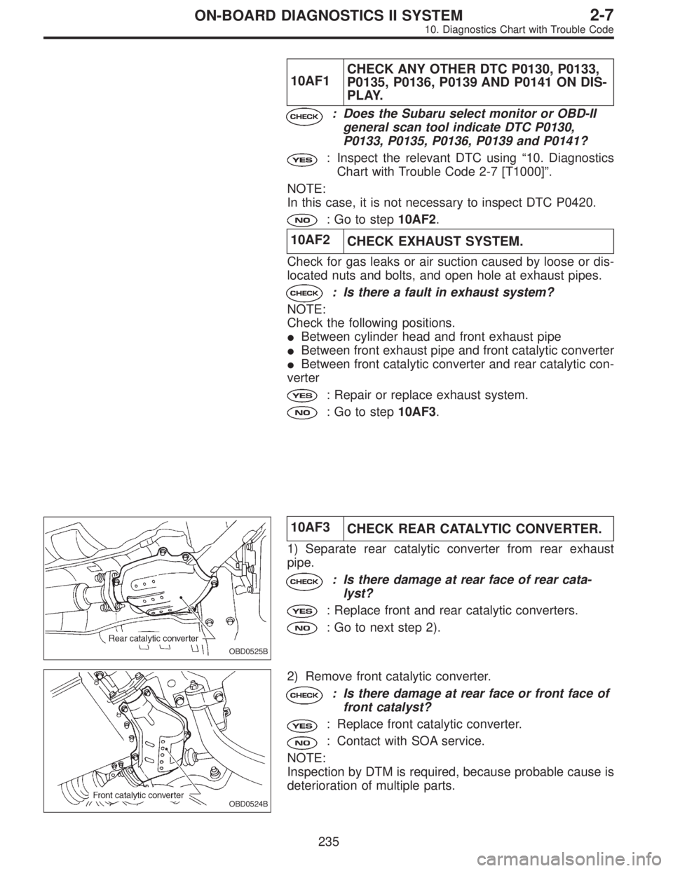
OBD0525B
10AF3
CHECK REAR CATALYTIC CONVERTER.
1) Separate rear catalytic converter from rear exhaust
pipe.
: Is there damage at rear face of rear cata-
lyst?
: Replace front and rear catalytic converters.
: Go to next step 2).
OBD0524B
2) Remove front catalytic converter.
: Is there damage at rear face or front face of
front catalyst?
: Replace front catalytic converter.
: Contact with SOA service.
NOTE:
Inspection by DTM is required, because probable cause is
deterioration of multiple parts.
235
2-7ON-BOARD DIAGNOSTICS II SYSTEM
10. Diagnostics Chart with Trouble Code
Page 2008 of 2890

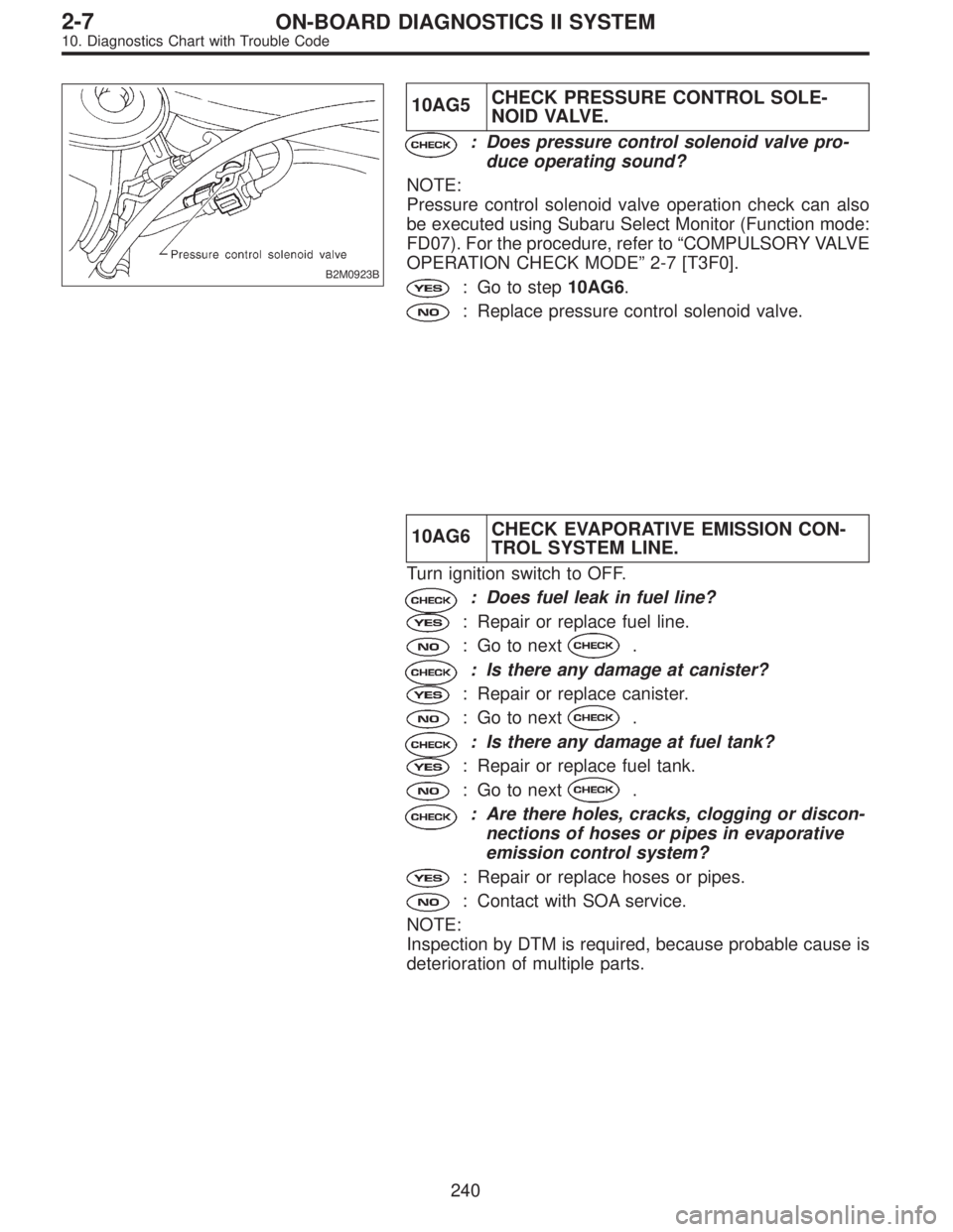
B2M0923B
10AG5CHECK PRESSURE CONTROL SOLE-
NOID VALVE.
: Does pressure control solenoid valve pro-
duce operating sound?
NOTE:
Pressure control solenoid valve operation check can also
be executed using Subaru Select Monitor (Function mode:
FD07). For the procedure, refer to“COMPULSORY VALVE
OPERATION CHECK MODE”2-7 [T3F0].
: Go to step10AG6.
: Replace pressure control solenoid valve.
10AG6CHECK EVAPORATIVE EMISSION CON-
TROL SYSTEM LINE.
Turn ignition switch to OFF.
: Does fuel leak in fuel line?
: Repair or replace fuel line.
: Go to next.
: Is there any damage at canister?
: Repair or replace canister.
: Go to next.
: Is there any damage at fuel tank?
: Repair or replace fuel tank.
: Go to next.
: Are there holes, cracks, clogging or discon-
nections of hoses or pipes in evaporative
emission control system?
: Repair or replace hoses or pipes.
: Contact with SOA service.
NOTE:
Inspection by DTM is required, because probable cause is
deterioration of multiple parts.
240
2-7ON-BOARD DIAGNOSTICS II SYSTEM
10. Diagnostics Chart with Trouble Code
Page 2016 of 2890
OBD0339A
10AI5CHECK POWER SUPPLY TO PURGE
CONTROL SOLENOID VALVE.
1) Turn ignition switch to ON.
2) Measure voltage between purge control solenoid valve
and engine ground.
: Connector & terminal
(E4) No. 1 (+)—Engine ground (�):
Is the voltage more than 10 V?
: Go to next.
: Repair open circuit in harness between main relay
and purge control solenoid valve connector.
: Is there poor contact in purge control sole-
noid valve connector?
: Repair poor contact in purge control solenoid
valve connector.
: Contact with SOA service.
NOTE:
Inspection by DTM is required, because probable cause is
deterioration of multiple parts.
248
2-7ON-BOARD DIAGNOSTICS II SYSTEM
10. Diagnostics Chart with Trouble Code
Page 2022 of 2890
H2M1241C
10AJ5CHECK POWER SUPPLY TO VENT CON-
TROL SOLENOID VALVE.
1) Turn ignition switch to ON.
2) Measure voltage between vent control solenoid valve
and chassis ground.
: Connector & terminal
(R69) No. 1 (+)—Chassis ground (�):
Is the voltage more than 10 V?
: Go to next.
: Repair harness and connector.
NOTE:
In this case, repair the following:
�Open circuit in harness between main relay and vent
control solenoid valve
�Poor contact in coupling connectors (B97 and R57)
�Poor contact in main relay connector
: Is there poor contact in vent control sole-
noid valve connector?
: Repair poor contact in vent control solenoid valve
connector.
: Contact with SOA service.
NOTE:
Inspection by DTM is required, because probable cause is
deterioration of multiple parts.
254
2-7ON-BOARD DIAGNOSTICS II SYSTEM
10. Diagnostics Chart with Trouble Code
Page 2043 of 2890
: Connector & terminal
(B84) No. 14—Chassis ground:
Is the resistance less than 10Ω?
: Repair short circuit in harness between ECM and
idle air control solenoid valve connector.
: Go to next.
: Is there poor contact in idle air control sole-
noid valve connector?
: Repair poor contact in idle air control solenoid
valve connector.
: Contact with SOA service.
NOTE:
Inspection by DTM is required, because probable cause is
deterioration of multiple parts.
275
2-7ON-BOARD DIAGNOSTICS II SYSTEM
10. Diagnostics Chart with Trouble Code
Page 2095 of 2890
OBD0676A
10BL5CHECK POWER SUPPLY TO PRESSURE
SOURCES SWITCHING SOLENOID
VA LV E .
1) Turn ignition switch to ON.
2) Measure voltage between pressure sources switching
solenoid valve harness connector and engine ground.
: Connector & terminal
(B1) No. 2 (+)—Engine ground (�):
Is the voltage more than 10 V?
: Go to next.
: Repair open circuit in harness between main relay
and pressure sources switching solenoid valve
connector.
: Is there poor contact in pressure sources
switching solenoid valve connector?
: Repair poor contact in pressure sources switching
solenoid valve connector.
: Contact with SOA service.
NOTE:
Inspection by DTM is required, because probable cause is
deterioration of multiple parts.
327
2-7ON-BOARD DIAGNOSTICS II SYSTEM
10. Diagnostics Chart with Trouble Code
Page 2104 of 2890
B2M0932A
10BN5CHECK POWER SUPPLY TO FUEL TANK
PRESSURE CONTROL SOLENOID
VA LV E .
1) Turn ignition switch to ON.
2) Measure voltage between fuel tank pressure control
solenoid valve and chassis ground.
: Connector & terminal
(R68) No. 1 (+)—Chassis ground (�):
Is the voltage more than 10 V?
: Go to next.
: Repair harness and connector.
NOTE:
In this case, repair the following:
�Open circuit in harness between main relay and fuel tank
pressure control solenoid valve connector
�Poor contact in coupling connectors (B97 and R57)
�Poor contact in main relay connector
: Is there poor contact in fuel tank pressure
control solenoid valve connector?
: Repair poor contact in fuel tank pressure control
solenoid valve connector.
: Contact with SOA service.
NOTE:
Inspection by DTM is required, because probable cause is
deterioration of multiple parts.
336
2-7ON-BOARD DIAGNOSTICS II SYSTEM
10. Diagnostics Chart with Trouble Code
Page 2112 of 2890
G2M0863
10BP5
CHECK FUEL SUB LEVEL SENSOR.
1) Remove service hole cover located on the left rear of
trunk compartment floor (Sedan) or luggage compartment
floor (Wagon).
B2M0936
2) Disconnect connector from fuel sub meter unit.
3) Measure resistance between connector terminals of
fuel sub meter unit.
: Terminals
No. 1—No. 2:
Is the resistance less than 100Ω?
: Go to step10BP6.
: Replace fuel sub meter unit.
B2M0937A
10BP6CHECK HARNESS BETWEEN FUEL
PUMP AND FUEL SUB METER UNIT
CONNECTOR.
Measure resistance of harness between fuel pump and fuel
sub meter unit connector.
: Connector & terminal
(R58) No. 3—(R59) No. 2:
Is the resistance less than 1Ω?
: Go to step10BP7.
: Repair open circuit in harness between fuel pump
and fuel sub meter unit connector.
344
2-7ON-BOARD DIAGNOSTICS II SYSTEM
10. Diagnostics Chart with Trouble Code