Page 1722 of 2890
B6M0379
Rear Gate Switch (WAGON)
1) Disconnect connector of rear gate key cylinder switch.
2) Move switch by turning the key cylinder with ignition key
and check continuity between terminals as indicated in
table below:
Terminal
Switch position124
Normal
LOCK��
UNLOCK��
B6M0133A
B6M0381A
5. DOOR LOCK/UNLOCK SWITCH
NOTE:
The door lock/unlock switch is united with the power door
lock actuator.
1) Disconnect connector of door lock/unlock switch.
2) Set switch to each position and check continuity
between terminals as indicated in table below:
Driver’s Door
Terminal
Switch position12
UNLOCK��
LOCK
Passenger’s Door
Terminal
Switch position1234
UNLOCK��
LOCK
Rear Gate (WAGON)
Terminal
Switch position1234
UNLOCK��
LOCK
58
6-2SERVICE PROCEDURE
22. Security System
Page 1723 of 2890
6. DOOR SWITCH
Refer to 6-2 [W8B1] as for inspection of door switch.
NOTE:
The door switch is combined with the door switch for room
light.
7. TRUNK LID SWITCH (SEDAN)
Refer to 6-2 [W8B2] as for inspection of trunk lid switch.
NOTE:
The trunk lid switch is combined with the trunk room light
switch.
8. REAR GATE SWITCH (WAGON)
Refer to 6-2 [W8B3] as for inspection of rear gate switch.
NOTE:
The rear gate switch is combined with the luggage room
light switch.
B6M0382A
9. SECURITY INDICATOR LIGHT
1) Remove security indicator light.
2) Check continuity between terminals of security indicator
light.
3) If there is no continuity, the indicator light will be fail-
ured.
Terminals: No. 2—No. 4
10. SECURITY CONTROL MODULE
Refer to 6-2 [K600]:“6. SECURITY SYSTEM”for inspec-
tion of security control module.
59
6-2SERVICE PROCEDURE
22. Security System
Page 1724 of 2890

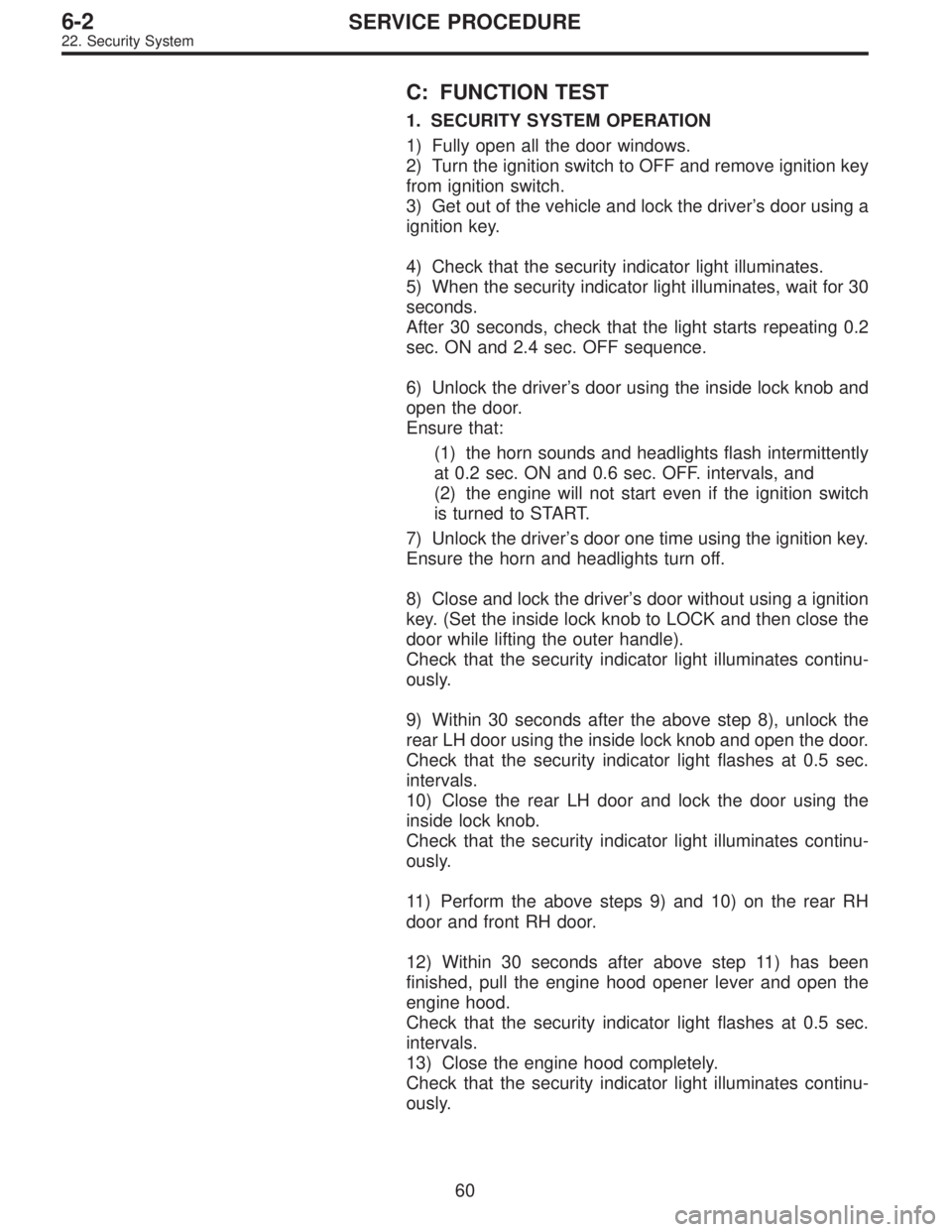
C: FUNCTION TEST
1. SECURITY SYSTEM OPERATION
1) Fully open all the door windows.
2) Turn the ignition switch to OFF and remove ignition key
from ignition switch.
3) Get out of the vehicle and lock the driver’s door using a
ignition key.
4) Check that the security indicator light illuminates.
5) When the security indicator light illuminates, wait for 30
seconds.
After 30 seconds, check that the light starts repeating 0.2
sec. ON and 2.4 sec. OFF sequence.
6) Unlock the driver’s door using the inside lock knob and
open the door.
Ensure that:
(1) the horn sounds and headlights flash intermittently
at 0.2 sec. ON and 0.6 sec. OFF. intervals, and
(2) the engine will not start even if the ignition switch
is turned to START.
7) Unlock the driver’s door one time using the ignition key.
Ensure the horn and headlights turn off.
8) Close and lock the driver’s door without using a ignition
key. (Set the inside lock knob to LOCK and then close the
door while lifting the outer handle).
Check that the security indicator light illuminates continu-
ously.
9) Within 30 seconds after the above step 8), unlock the
rear LH door using the inside lock knob and open the door.
Check that the security indicator light flashes at 0.5 sec.
intervals.
10) Close the rear LH door and lock the door using the
inside lock knob.
Check that the security indicator light illuminates continu-
ously.
11) Perform the above steps 9) and 10) on the rear RH
door and front RH door.
12) Within 30 seconds after above step 11) has been
finished, pull the engine hood opener lever and open the
engine hood.
Check that the security indicator light flashes at 0.5 sec.
intervals.
13) Close the engine hood completely.
Check that the security indicator light illuminates continu-
ously.
60
6-2SERVICE PROCEDURE
22. Security System
Page 1725 of 2890

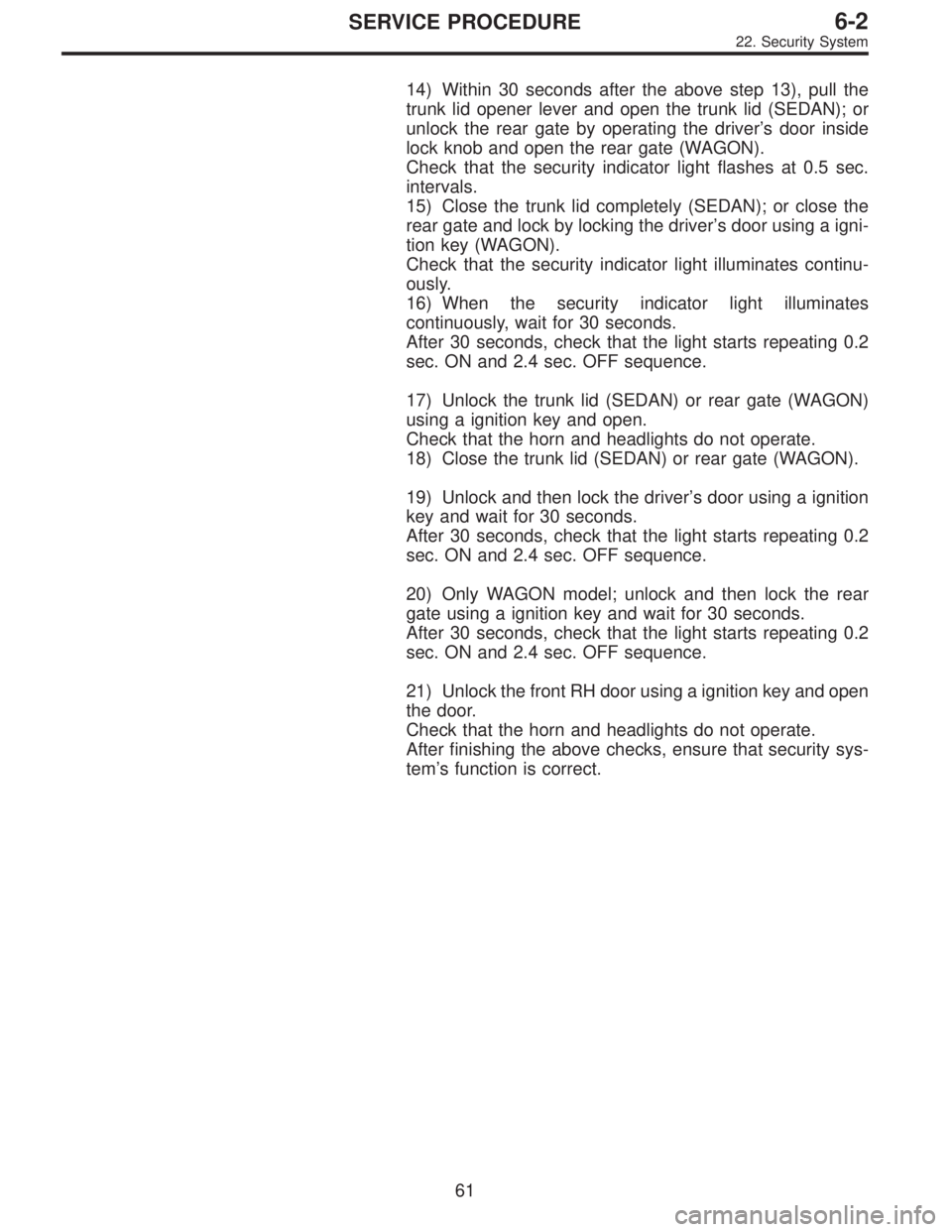
14) Within 30 seconds after the above step 13), pull the
trunk lid opener lever and open the trunk lid (SEDAN); or
unlock the rear gate by operating the driver’s door inside
lock knob and open the rear gate (WAGON).
Check that the security indicator light flashes at 0.5 sec.
intervals.
15) Close the trunk lid completely (SEDAN); or close the
rear gate and lock by locking the driver’s door using a igni-
tion key (WAGON).
Check that the security indicator light illuminates continu-
ously.
16) When the security indicator light illuminates
continuously, wait for 30 seconds.
After 30 seconds, check that the light starts repeating 0.2
sec. ON and 2.4 sec. OFF sequence.
17) Unlock the trunk lid (SEDAN) or rear gate (WAGON)
using a ignition key and open.
Check that the horn and headlights do not operate.
18) Close the trunk lid (SEDAN) or rear gate (WAGON).
19) Unlock and then lock the driver’s door using a ignition
key and wait for 30 seconds.
After 30 seconds, check that the light starts repeating 0.2
sec. ON and 2.4 sec. OFF sequence.
20) Only WAGON model; unlock and then lock the rear
gate using a ignition key and wait for 30 seconds.
After 30 seconds, check that the light starts repeating 0.2
sec. ON and 2.4 sec. OFF sequence.
21) Unlock the front RH door using a ignition key and open
the door.
Check that the horn and headlights do not operate.
After finishing the above checks, ensure that security sys-
tem’s function is correct.
61
6-2SERVICE PROCEDURE
22. Security System
Page 1726 of 2890
23. Seat Heater
A: REMOVAL AND INSTALLATION
1. SEAT HEATER
Refer to 5-3 [W1A0] as for removal of seat (including
heater system).
B6M0150A
2. SEAT HEATER SWITCH
1) Remove screws which secure rear console cover, and
then remove rear console cover.
2) Remove seat heater switch from console cover.
B6M0151A
B: INSPECTION
1. SEAT HEATER
Check continuity between terminals of seat heater connec-
tor.
�Between terminals No. 1 and No. 3
�Between terminals No. 1 and No. 4
�Between terminals No. 3 and No. 4
B6M0152
2. SEAT HEATER SWITCH
Set switch to each position and check continuity between
terminals as indicated in table below:
Terminal
Switch562 34 1
OFF�
���
LO������
HI
��
��
�
���
62
6-2SERVICE PROCEDURE
23. Seat Heater
Page 1886 of 2890

9. General Diagnostics Table
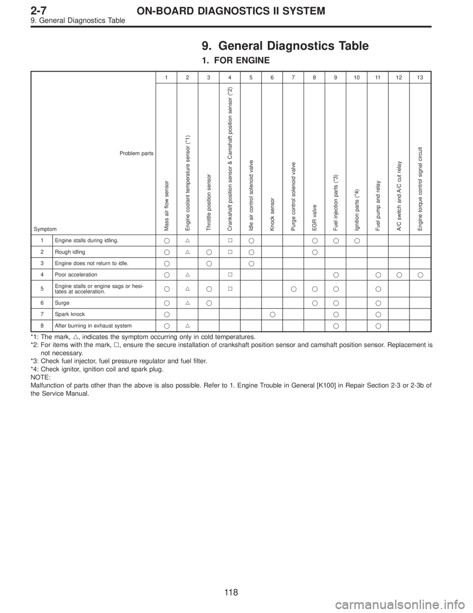
1. FOR ENGINE
12345678910111213
Problem parts
Mass air flow sensor
Engine coolant temperature sensor (*1)
Throttle position sensor
Crankshaft position sensor & Camshaft position sensor (*2)
Idle air control solenoid valve
Knock sensor
Purge control solenoid valve
EGR valve
Fuel injection parts (*3)
Ignition parts (*4)
Fuel pump and relay
A/C switch and A/C cut relay
Engine torque control signal circuitSymptom
1 Engine stalls during idling.�� � � ���
2 Rough idling�� � � � �
3 Engine does not return to idle.���
4 Poor acceleration�� � � ���
5Engine stalls or engine sags or hesi-
tates at acceleration.�� � � ��� �
6 Surge�� � �� �
7 Spark knock����
8 After burning in exhaust system�� � �
*1: The mark,�, indicates the symptom occurring only in cold temperatures.
*2: For items with the mark,�, ensure the secure installation of crankshaft position sensor and camshaft position sensor. Replacement is
not necessary.
*3: Check fuel injector, fuel pressure regulator and fuel filter.
*4: Check ignitor, ignition coil and spark plug.
NOTE:
Malfunction of parts other than the above is also possible. Refer to 1. Engine Trouble in General [K100] in Repair Section 2-3 or 2-3b of
the Service Manual.
11 8
2-7ON-BOARD DIAGNOSTICS II SYSTEM
9. General Diagnostics Table
Page 1957 of 2890

OBD0145A
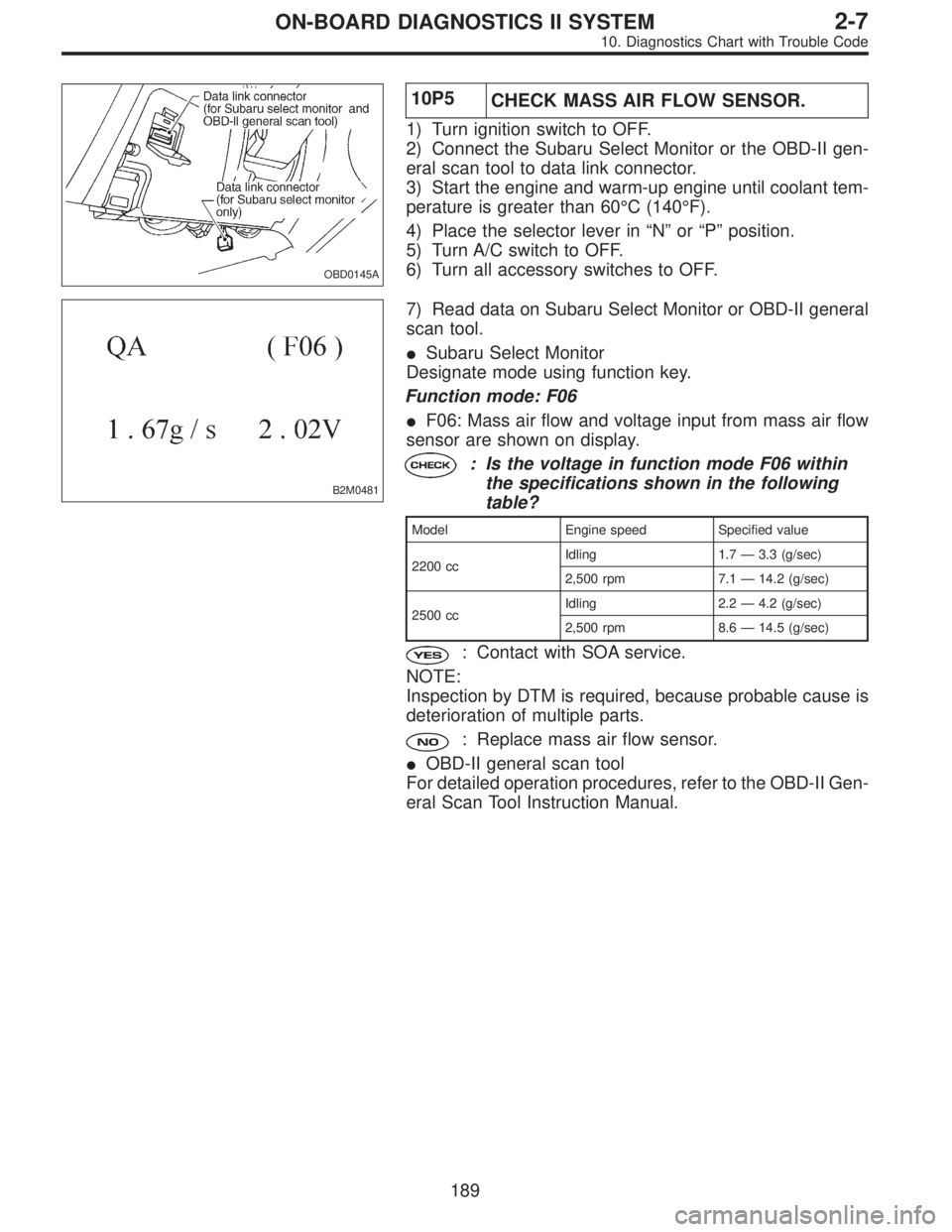
10P5
CHECK MASS AIR FLOW SENSOR.
1) Turn ignition switch to OFF.
2) Connect the Subaru Select Monitor or the OBD-II gen-
eral scan tool to data link connector.
3) Start the engine and warm-up engine until coolant tem-
perature is greater than 60°C (140°F).
4) Place the selector lever in“N”or“P”position.
5) Turn A/C switch to OFF.
6) Turn all accessory switches to OFF.
B2M0481
7) Read data on Subaru Select Monitor or OBD-II general
scan tool.
�Subaru Select Monitor
Designate mode using function key.
Function mode: F06
�F06: Mass air flow and voltage input from mass air flow
sensor are shown on display.
: Is the voltage in function mode F06 within
the specifications shown in the following
table?
Model Engine speed Specified value
2200 ccIdling 1.7—3.3 (g/sec)
2,500 rpm 7.1—14.2 (g/sec)
2500 ccIdling 2.2—4.2 (g/sec)
2,500 rpm 8.6—14.5 (g/sec)
: Contact with SOA service.
NOTE:
Inspection by DTM is required, because probable cause is
deterioration of multiple parts.
: Replace mass air flow sensor.
�OBD-II general scan tool
For detailed operation procedures, refer to the OBD-II Gen-
eral Scan Tool Instruction Manual.
189
2-7ON-BOARD DIAGNOSTICS II SYSTEM
10. Diagnostics Chart with Trouble Code
Page 2000 of 2890
OBD0327
10AE5
CHECK EGR SOLENOID VALVE.
Measure resistance between EGR solenoid valve termi-
nals.
: Terminals
No. 1—No. 2:
Is the resistance between 10 and 100Ω?
: Go to step10AE6.
: Replace EGR solenoid valve.
OBD0328A
10AE6CHECK POWER SUPPLY TO EGR SOLE-
NOID VALVE.
1) Turn ignition switch to ON.
2) Measure voltage between EGR solenoid valve and
engine ground.
: Connector & terminal
(E18) No. 1 (+)—Engine ground (�):
Is the voltage more than 10 V?
: Go to next.
: Repair open circuit in harness between main relay
and EGR solenoid valve connector.
: Is there poor contact in EGR solenoid valve
connector?
: Repair poor contact in EGR solenoid valve con-
nector.
: Contact with SOA service.
NOTE:
Inspection by DTM is required, because probable cause is
deterioration of multiple parts.
232
2-7ON-BOARD DIAGNOSTICS II SYSTEM
10. Diagnostics Chart with Trouble Code