Page 1201 of 2890

While engine is run-
ning with maximum
turning angle.
Relief valve soundGenerates at max.
turning angle.Normal (Don’t keep
this condition over 5
s")
6. NOISE AND VIBRATION
*6
Hiss noise (continu-
ous)
While engine is run-
ning with maximum
turning angle.
Relief valve soundGenerates at max.
turning angle.Normal (Don’t keep
this condition over 5
seconds.)
Generates without
steering operation.Defective
Replace oil pump.
Rattling noise
(intermittent)
While engine is run-
ning.Interference with adjacent partsCheck clearance.
[Refer to next article
6.]
Correct if necessary.
Loosened installation of oil pump, oil tank, pump bracket,
gearbox or crossmember.Retighten.
Loosened installation of oil pump pulley or other pulley(s).Retighten.
Loosened linkage or play of steering or suspension.
Loosened tightening of joint or steering column.Retighten or replace.
Sound generates from the inside of gearbox or oil pump.Replace the gearbox
or oil pump.
Knocking
When turning steer-
ing wheel in both
direction with small
angle repeatedly at
engine ON or OFF.Excessive backlash
Loosened lock nut for adjusting backlash.Adjust and retighten.
Loosened tightening or play of tie-rod, tie-rod end.Retighten or replace.
*6 Don’t keep the relief valve operated over 5 sec. at any time or inner parts of the oil pump may be damaged due to rapid increase
of fluid temperature.
94
4-3DIAGNOSTICS
1. Power Steering
Page 1258 of 2890

G4M0744
2. AIR TIGHTNESS CHECK
Start engine, and run it for 1 to 2 minutes, then turn it off.
Depress brake pedal several times applying the same
pedal force as that used in ordinary braking operations.
The pedal stroke should be greatest on the 1st depression,
and it should become smaller with each successive
depression. If no change occurs in the pedal height while
in a depressed state, brake booster is faulty.
NOTE:
�In the event of defective operation, inspect the condition
of the check valve and vacuum hose.
�Replace them if faulty and conduct the test again.
�If no improvement is observed, check precisely with
gauges.
G4M0914
3. OPERATION CHECK
1) With engine off, depress brake pedal several times
applying the same pedal force and make sure that the
pedal height does not vary with each depression of the
pedal.
2) With brake pedal depressed, start engine.
3) As engine starts, brake pedal should move slightly
toward the floor. If no change occurs in the pedal height,
brake booster is faulty.
NOTE:
If faulty, check precisely with gauges.
4. LOADED AIR TIGHTNESS CHECK
Depress brake pedal while engine is running, and turn off
engine while the pedal is still depressed. Keep the pedal
depressed for 30 seconds; if no change occurs in the pedal
height, brake booster is functioning normally; if the pedal
height increases, it is faulty.
NOTE:
If faulty, check precisely with gauges.
52
4-4SERVICE PROCEDURE
6. Brake Booster
Page 1259 of 2890
 Start engine and keep it running un")
G4M0423
5. CHECKING WITH GAUGES
Connect gauges as shown in Figure. After bleeding air from
pressure gauges, proceed to each check.
G4M0746
6. AIR TIGHTNESS CHECK
1) Start engine and keep it running until a vacuum of 66.7
kPa (500 mmHg, 19.69 inHg) = point A is indicated on
vacuum gauge. Do not depress brake pedal.
2) Stop engine and watch the gauge. If the vacuum drop
range is less than 3.3 kPa (25 mmHg, 0.98 inHg) within 15
seconds after stopping engine, brake booster is functioning
properly.
If defective, the cause may be one of those listed below.
�Check valve malfunction
�Leak from vacuum hose
�Leak from the shell jointed portion or stud bolt welded
portion
�Damaged diaphragm
�Leak from valve body seal and bearing portion
�Leak from plate and seal assembly portion
�Leak from poppet valve assembly portion
G4M0747
7. LOADED AIR TIGHTNESS CHECK
1) Start engine and depress brake pedal with pedal force
of 196 N (20 kg, 44 lb). Keep engine running until a vacuum
of 66.7 kPa (500 mmHg, 19.69 inHg) = point B is indicated
on vacuum gauge while the pedal is still depressed.
2) Stop engine and watch vacuum gauge.
If the vacuum drop range is less than 3.3 kPa (25 mmHg,
0.98 inHg) within 15 seconds after stopping engine, brake
booster is functioning properly.
If defective, refer to“AIR TIGHTNESS CHECK”described
above.
53
4-4SERVICE PROCEDURE
6. Brake Booster
Page 1260 of 2890

8. LACK OF BOOSTING ACTION CHECK
Turn off engine, and set the vacuum gauge reading at“0”.
Then, check the fluid pressure when brake pedal is
depressed. The pressure must be greater than the stan-
dard value listed below.
Brake pedal force 147N (15 kg, 33 lb) 294N (30kg, 66 lb)
Models without ABS and
TCS785 kPa
(8 kg/cm
2, 114 psi)2,158 kPa
(22 kg/cm2, 313 psi)
Models with ABS and
TCS588 kPa
(6 kg/cm
2, 85 psi)1,667 kPa
(17 kg/cm2, 242 psi)
9. BOOSTING ACTION CHECK
Set the vacuum gauge reading at 66.7 kPa (500 mmHg,
19.69 inHg) by running engine. Then, check the fluid pres-
sure when brake pedal is depressed. The pressure must
be greater than the standard value listed below.
Brake pedal force 147N (15 kg, 33 lb) 294N (30kg, 66 lb)
Models without ABS and
TCS5,492 kPa
(56 kg/cm
2, 796 psi)8,434 kPa
(86 kg/cm2, 1,223 psi)
Models with ABS and
TCS5,394 kPa
(55 kg/cm
2,782 psi)10,003 kPa
(102 kg/cm2, 1,450
psi)
D: HANDLING PRECAUTIONS
1) Be careful not to drop brake booster. Brake booster
should be discarded if it has been dropped.
2) Use special care when handling operating rod.
If excessive force is applied to operating rod, sufficient to
cause a change in the angle in excess of ±3°, it may result
in damage to the power piston cylinder.
54
4-4SERVICE PROCEDURE
6. Brake Booster
Page 1263 of 2890
 Drain brake fluid from reservoir of master cylinder.
2) Remove adjusting nut and cable clamp, and disconnect
PHV cable from cable bracket on engine.
3) Detach PHV")
G4M0428
8. Hill Holder
A: REMOVAL
1) Drain brake fluid from reservoir of master cylinder.
2) Remove adjusting nut and cable clamp, and disconnect
PHV cable from cable bracket on engine.
3) Detach PHV cable from clips.
4) Remove cable clamp, and disconnect PHV cable from
PHV stay.
CAUTION:
Carefully protect boots and inner cable from damage
when disconnecting PHV cable.
5) Disconnect brake pipes from PHV.
CAUTION:
�Pay attention not to drop brake fluid onto body
painting since it may dissolve paint.
�Pay attention not to damage hexagonal head of flare
nut by using pipe wrench without fail.
6) Detach PHV along with support from side frame.
CAUTION:
Exercise utmost care to prevent foreign matter from
entering into PHV when removing it.
B: INSPECTION
Check up removed parts as follows, and replace defective
ones.
1) Check if boots of PHV cable are damaged or degraded,
and if inner cable is damaged or corroded.
2) Check if return spring is worn out, damaged or cor-
roded.
3) Confirm that rolling sound of ball is heard with PHV
inclined and lever rotates smoothly.
CAUTION:
Never disassemble PHV. Replace entire PHV assembly
if necessary.
57
4-4SERVICE PROCEDURE
8. Hill Holder
Page 1270 of 2890

5) Perform these steps for the brakes connecting to the
secondary chamber of master cylinder, first, and then for
the ones con")
Air bleeder tightening torque:
8±1 N⋅m (0.8±0.1 kg-m, 5.8±0.7 ft-lb)
5) Perform these steps for the brakes connecting to the
secondary chamber of master cylinder, first, and then for
the ones connecting to primary chamber. With all proce-
dures completed, fully depress the brake pedal and keep
it in that position for approximately 20 seconds to make
sure that there is no leak evident in the entire system.
G4M0436
6) Perform sequence control. (With ABS model)
4-4 [W15C1].>
7) Check the pedal stroke.
While the engine is idling, depress the brake pedal with a
490 N (50 kg, 110 lb) load and measure the distance
between the brake pedal and steering wheel. With the
brake pedal released, measure the distance between the
pedal and steering wheel again. The difference between
the two measurements must be more than specified.
Specified pedal stroke:
Without ABS
90 mm (3.54 in)
With ABS
95 mm (3.74 in)
When depressing brake pedal with a 490 N (50 kg,
110 lb) load.
(1) Models without ABS
If the distance is more than specifications, there is a
possibility that air is in the brake line. Bleed air from the
brake line.
(2) Models with ABS
If the distance is more than specifications, there is a
possibility air is in the inside of the hydraulic unit.
Therefore, air must be bled from the inside of the
hydraulic unit to the brake pipes in accordance with the
bleeding sequence control.
8) Add brake fluid to the required level (MAX. level) of
reserve tank.
9) As a final step, test run the vehicle at low speed and
apply brakes relatively hard 2 to 3 times to ensure that
brakes provide normal braking action on all four wheels
without dragging and uneven braking.
63
4-4SERVICE PROCEDURE
11. Air Bleeding (Without TCS model)
Page 1282 of 2890
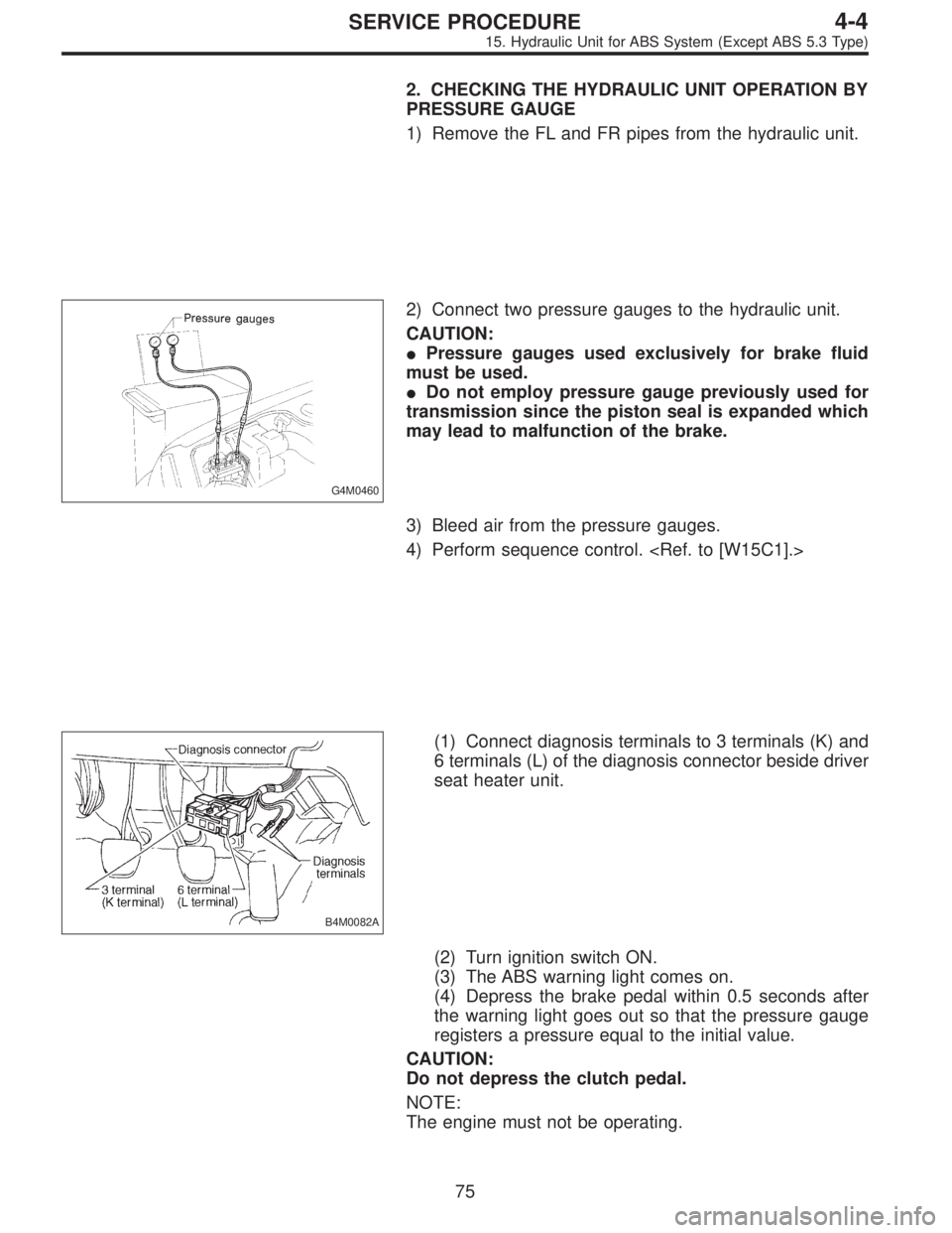
2. CHECKING THE HYDRAULIC UNIT OPERATION BY
PRESSURE GAUGE
1) Remove the FL and FR pipes from the hydraulic unit.
G4M0460
2) Connect two pressure gauges to the hydraulic unit.
CAUTION:
�Pressure gauges used exclusively for brake fluid
must be used.
�Do not employ pressure gauge previously used for
transmission since the piston seal is expanded which
may lead to malfunction of the brake.
3) Bleed air from the pressure gauges.
4) Perform sequence control.
B4M0082A
(1) Connect diagnosis terminals to 3 terminals (K) and
6 terminals (L) of the diagnosis connector beside driver
seat heater unit.
(2) Turn ignition switch ON.
(3) The ABS warning light comes on.
(4) Depress the brake pedal within 0.5 seconds after
the warning light goes out so that the pressure gauge
registers a pressure equal to the initial value.
CAUTION:
Do not depress the clutch pedal.
NOTE:
The engine must not be operating.
75
4-4SERVICE PROCEDURE
15. Hydraulic Unit for ABS System (Except ABS 5.3 Type)
Page 1284 of 2890
 In the case of AWD vehicles, install a spare fuse with
the FWD connector in the engine compartment to simulate
FWD vehicles.
B4M0082A
2) Con")
G4M0462
3. CHECKING THE HYDRAULIC UNIT WITH BRAKE
TESTER
1) In the case of AWD vehicles, install a spare fuse with
the FWD connector in the engine compartment to simulate
FWD vehicles.
B4M0082A
2) Connect diagnosis terminals to 3 terminals (K) and 6
terminals (L) of the diagnosis connector beside driver seat
heater unit.
G4M0464
3) Set the front wheels or rear wheels on the brake tester
and set the select lever’s position at“neutral”.
4) Operate the brake tester.
5) Perform sequence control.
(1) Turn ignition switch ON.
(2) The ABS warning light comes on.
(3) Depress the brake pedal within 0.5 seconds after
the warning light goes out so that the brake tester reg-
isters a pressure equal to the initial value.
CAUTION:
Do not depress the clutch pedal.
NOTE:
The engine must not be operating.
6) Hydraulic unit begins to work; and check the following
working sequence.
(1) The left front wheel performs decompression,
holding, and compression in sequence, and subse-
quently the right front wheel repeats the cycle.
(2) Simultaneously both right and left rear wheel per-
form decompression, holding, and compression in
sequence.
77
4-4SERVICE PROCEDURE
15. Hydraulic Unit for ABS System (Except ABS 5.3 Type)