Page 1 of 2890
1-1
[s2o2]
SPECIFICATIONS
2
.
Station
Wagon
2
.
Station
Wagon
2
.
ENGINE
Engine
type
Horizontally
opposed,
liquid
cooled,
4-cylinder,
4-stroke
gasoline
engine
Valve
arrangement
Overhead
camshaft
type
Bore
x
Stroke
mm
(in)
96
.9
x75
.0(3
.815
x2
.953)
Displacement
cm3
(cu
in)
2,212
(135
.0)
Compression
ratio
9
.7
Firing
order
1-3-2-4
Idle
speed
at
Park/Neutral
position
rpm700
Maximum
output
kW
(HP)/rpm
101
(135)/5,400
Maximum
torque
N
.m
(kg-m,
ft-Ib)/rpm
190
(19
.4,140)/4,400
3
.
ELECTRICAL
Ignition
timing
atidling
speed
BTDC/rpm
20°/700
Spark
plug
Type
and
manufacturer
CHAMPION
:
RC10YC4
(Standard)
NGK
:
BKR6E-11
NIPPONDENSO
:
K20PR-U11
Generator
12V
-
85A
Battery
Reserve
capacity
min100
Cold
cranking
amperes
amp
.I
490
Page 36 of 2890
[T3C13]
2-7
ON-BOARD
DIAGNOSTICS
II
SYSTEM
3
.
Diagnosis
System
VSP
(F02)
24km/
h
15MPH
B2M0754
EREV
(F03
)
1500
rpm
B2M0478
TW
(F04)
800C
176
°
F
B2M0479
ADVS
(F05
)
15
deg
B2M0480
QA
(
F06
)
1
.
67g
l
s
2
.
02V
82M0481
9
.
FUNCTION
MODE
:
F02
-
VEHICLE
SPEED
SIGNAL
(VSP)
-
9
Vehicle
speed
is
indicated
in
kilometerper
hour
(km/h)
and
mile
per
hour
(MPH)
at
the
same
time
.
10
.
FUNCTION
MODE
:
F03
-
ENGINE
SPEED
SIGNAL
(EREV)
-
11
.
FUNCTION
MODE
:
F04
-
ENGINE
COOLANT
TEMPERATURE
SIGNAL
(TW)
-
~
Engine
coolant
temperature
is
indicated
in
"°C"
and
"°F"
at
the
same
time
.
12
.
FUNCTION
MODE
:
F05
-
IGNITION
SIGNAL
(ADVS)
-
NOTE
:
The
ignition
timing
value
displayed
in
mode
F05
is
a
value
computed
by
ECM
and
will
not
alwayscorrespond
with
the
value
measured
with
a
timing
light
.
13
.
FUNCTION
MODE
:
F06
-
MASS
AIR
FLOW
SIGNAL
(QA)
-
Mass
air
flow
and
voltage
input
from
mass
air
flow
sensorare
shown
on
display
at
the
same
time
.
21
Page 38 of 2890
ON-BOARD
DIAGNOSTICS
II
SYSTEM
[T3C23]
2-7
3
.
Diagnosis
System
02max
-
min
(
F
12
)
0
.
80V
0
.
10v
BMW
R02
(F13)
0
.
60
V
B2M0488
R02max
-
min
(F14)
0
.
80V
0
.
10V
82M0489
ALPHA
(F17)
0
.8
B2M0490
KNOCK
(F19)
3
.
0deg
82M0491
19
.
FUNCTION
MODE
:
F12
-
FRONT
OXYGENSENSOR
MAXIMUM
AND
MINIMUM
OUTPUT
SIGNAL
(F02MAX
-
MIN)
-
Front
oxygen
sensor
maximum
andminimum
output
signals
are
indicated
at
the
same
time
.
20
.
FUNCTION
MODE
:
F13
-
REAR
OXYGENSENSOR
OUTPUT
SIGNAL
(R02)
-
21
.
FUNCTION
MODE
:
F14
-
REAR
OXYGEN
SENSOR
MAXIMUM
AND
MINIMUM
OUTPUT
SIGNAL
(R02MAX
-
MIN)
-
oRear
oxygen
sensor
maximum
and
minimum
output
sig-
nals
are
indicated
at
the
same
time
.
22
.
FUNCTION
MODE
:
F17
-
SHORTTERM
FUEL
TRIM
[A/F
CORRECTION
COEFFICIENT]
(ALPHA)
-
23
.
FUNCTION
MODE
:
F19
-
KNOCK
SENSOR
SIGNAL
[IGNITION
TIMING
CORRECTION
COEFFICIENT]
(KNOCK)
-
23
Page 302 of 2890

1. Foreword
This chapter describes major inspection and service pro-
cedures for the engine mounted on the body. For proce-
dures not found in this chapter, refer to the service proce-
dure section in the applicable chapter.
2. Ignition Timing
A: MEASUREMENT
1. 2200 cc MODEL
1) Warm-up the engine.
G2M0094
2) To check the ignition timing, connect a timing light to #1
cylinder spark plug cord, and illuminate the timing mark
with the timing light.
3) Start the engine at idle speed and check the ignition
timing.
If the timing is not correct, check the ignition control sys-
tem.
Ignition timing [BTDC/rpm]:
14°±8°/700 (MT)
20°±8°/700 (AT)
2. 2500 cc MODEL
CAUTION:
After warming-up, engine becomes very hot. Be care-
ful not to burn yourself during measurement.
1) Warm-up the engine.
B2M0750A
2) To check the ignition timing, connect a timing light to #1
cylinder spark plug cord, and illuminate the timing mark
with the timing light.
3) Start the engine at idle speed and check the ignition
timing.
If the timing is not correct, check the ignition control sys-
tem.
Ignition timing [BTDC/rpm]:
15°±8°/700
2
2-2
1. Foreword - 2. Ignition Timing
Page 303 of 2890

1. Foreword
This chapter describes major inspection and service pro-
cedures for the engine mounted on the body. For proce-
dures not found in this chapter, refer to the service proce-
dure section in the applicable chapter.
2. Ignition Timing
A: MEASUREMENT
1. 2200 cc MODEL
1) Warm-up the engine.
G2M0094
2) To check the ignition timing, connect a timing light to #1
cylinder spark plug cord, and illuminate the timing mark
with the timing light.
3) Start the engine at idle speed and check the ignition
timing.
If the timing is not correct, check the ignition control sys-
tem.
Ignition timing [BTDC/rpm]:
14°±8°/700 (MT)
20°±8°/700 (AT)
2. 2500 cc MODEL
CAUTION:
After warming-up, engine becomes very hot. Be care-
ful not to burn yourself during measurement.
1) Warm-up the engine.
B2M0750A
2) To check the ignition timing, connect a timing light to #1
cylinder spark plug cord, and illuminate the timing mark
with the timing light.
3) Start the engine at idle speed and check the ignition
timing.
If the timing is not correct, check the ignition control sys-
tem.
Ignition timing [BTDC/rpm]:
15°±8°/700
2
2-2
1. Foreword - 2. Ignition Timing
Page 304 of 2890
 Before checking idle speed, check the following:
(1) Ensure that air cleaner element is free from
clogging, ignition timing is correct, spark plugs are in
good c")
3. Engine Idle Speed
A: MEASUREMENT
1) Before checking idle speed, check the following:
(1) Ensure that air cleaner element is free from
clogging, ignition timing is correct, spark plugs are in
good condition, and that hoses are connected properly.
(2) Ensure that malfunction indicator light (CHECK
ENGINE light) does not illuminate.
2) Warm-up the engine.
G2M0096
3) Connect Subaru Select Monitor or the OBD-II general
scan tool to data link connector.
CAUTION:
When connecting Subaru Select Monitor, turn ignition
switch to OFF.
4) Start the engine and measure engine speed.
NOTE:
Engine speed is indicated on Subaru Select Monitor by
selecting “MODE F04”.
G2M0097
NOTE:
�When using the OBD-II general scan tool, carefully read
its operation manual.
�When Subaru Select Monitor is not used, attach the
pickup sensor on tachometer (Secondary pickup type) to
#1 cylinder spark plug cord.
�This ignition system provides simultaneous ignition for
#1 and #2 plugs. It must be noted that some tachometers
may register twice that of actual engine speed.
5) Check idle speed when unloaded. (With headlights,
heater fan, rear defroster, radiator fan, air conditioning, etc.
OFF)
Idle speed (No load and gears in neutral (MT) or N or
P (AT) position):
700±100 rpm
6) Check idle speed when loaded. (Turn air conditioning
switch to “ON” and operate compressor for at least one
minute before measurement.)
Idle speed [A/C“ON”, no load and gears in neutral
(MT) or N or P (AT) position]:
850±50 rpm
CAUTION:
Never rotate idle adjusting screw. If idle speed is out
of specifications, refer to General On-board Diagnosis
Table under “2-7 On-Board Diagnostics II System”.
3
2-2
3. Engine Idle Speed
Page 310 of 2890
1. Engine
A: SPECIFICATIONS
EngineModel2200 cc
TypeHorizontally opposed, liquid cooled, 4-cylinder, 4-stroke
gasoline engine
Valve arrangement Belt driven, single over-head camshaft, 4-valve/cylinder
Bore x Stroke mm (in) 96.9 x 75.0 (3.815 x 2.953)
Displacement cm
3(cu in) 2,212 (135.0)
Compression ratio9.7
Compression pressure
(at 200 — 300 rpm)kPa (kg/cm
2, psi)1,079 — 1,275
(11.0 — 13.0, 156 — 185)
Number of piston rings Pressure ring: 2, Oil ring: 1
Intake valve timingOpening 1° BTDC
Closing 55° ABDC
Exhaust valve timingOpening 48° BBDC
Closing 12° ATDC
Idling speed
[At neutral position on MT, or
“P” or “N” position on AT] rpm700±100 (No load)
850±50 (A/C switch ON)
Firing order1,3,2,4
Ignition timing BTDC/rpm 14°±8°/700 (MT), 20°±8°/700 (AT)
2
2-3SPECIFICATIONS AND SERVICE DATA
1. Engine
Page 314 of 2890
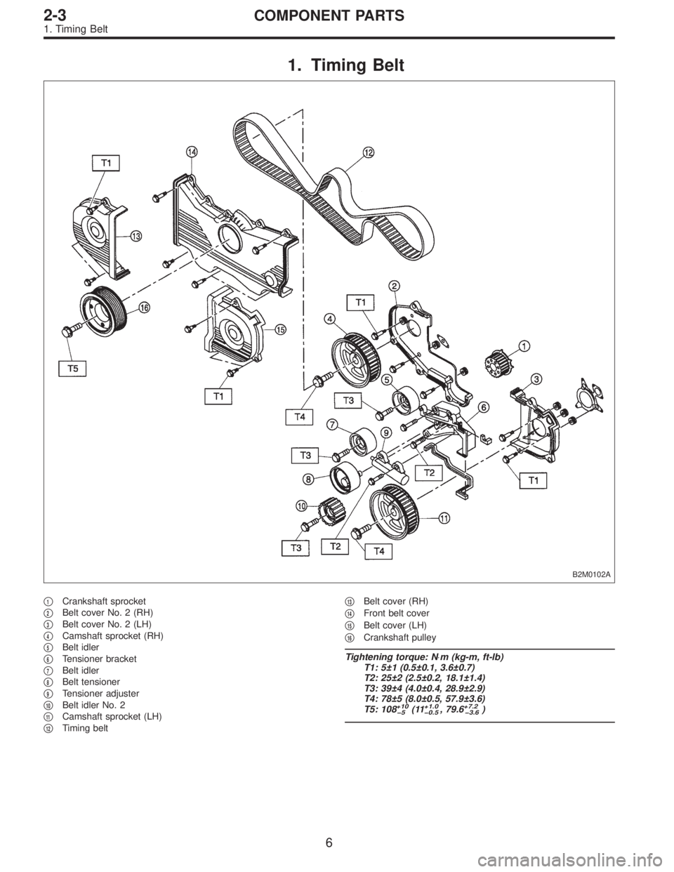
1. Timing Belt
B2M0102A
�1Crankshaft sprocket
�
2Belt cover No. 2 (RH)
�
3Belt cover No. 2 (LH)
�
4Camshaft sprocket (RH)
�
5Belt idler
�
6Tensioner bracket
�
7Belt idler
�
8Belt tensioner
�
9Tensioner adjuster
�
10Belt idler No. 2
�
11Camshaft sprocket (LH)
�
12Timing belt�
13Belt cover (RH)
�
14Front belt cover
�
15Belt cover (LH)
�
16Crankshaft pulley
Tightening torque: N⋅m (kg-m, ft-lb)
T1: 5±1 (0.5±0.1, 3.6±0.7)
T2: 25±2 (2.5±0.2, 18.1±1.4)
T3: 39±4 (4.0±0.4, 28.9±2.9)
T4: 78±5 (8.0±0.5, 57.9±3.6)
T5: 108
+10
�5(11+1.0
�0.5, 79.6+7.2
�3.6)
6
2-3COMPONENT PARTS
1. Timing Belt
![SUBARU LEGACY 1996 Service Repair Manual
1-1
[s2o2]
SPECIFICATIONS
2
.
Station
Wagon
2
.
Station
Wagon
2
.
ENGINE
Engine
type
Horizontally
opposed,
liquid
cooled,
4-cylinder,
4-stroke
gasoline
engine
Valve
arrangement
Overhead
camshaft](/manual-img/17/57433/w960_57433-0.png "SUBARU LEGACY 1996 Service Repair Manual
1-1
[s2o2]
SPECIFICATIONS
2
.
Station
Wagon
2
.
Station
Wagon
2
.
ENGINE
Engine
type
Horizontally
opposed,
liquid
cooled,
4-cylinder,
4-stroke
gasoline
engine
Valve
arrangement
Overhead
camshaft")
![SUBARU LEGACY 1996 Service Repair Manual
[T3C13]
2-7
ON-BOARD
DIAGNOSTICS
II
SYSTEM
3
.
Diagnosis
System
VSP
(F02)
24km/
h
15MPH
B2M0754
EREV
(F03
)
1500
rpm
B2M0478
TW
(F04)
800C
176
°
F
B2M0479
ADVS
(F05
)
15
deg
B2M0480
QA](/manual-img/17/57433/w960_57433-35.png "SUBARU LEGACY 1996 Service Repair Manual
[T3C13]
2-7
ON-BOARD
DIAGNOSTICS
II
SYSTEM
3
.
Diagnosis
System
VSP
(F02)
24km/
h
15MPH
B2M0754
EREV
(F03
)
1500
rpm
B2M0478
TW
(F04)
800C
176
°
F
B2M0479
ADVS
(F05
)
15
deg
B2M0480
QA")
![SUBARU LEGACY 1996 Service Repair Manual
ON-BOARD
DIAGNOSTICS
II
SYSTEM
[T3C23]
2-7
3
.
Diagnosis
System
02max
-
min
(
F
12
)
0
.
80V
0
.
10v
BMW
R02
(F13)
0
.
60
V
B2M0488
R02max
-
min
(F14)
0
.
80V
0
.
10V
82M0489
ALPHA
(F17)](/manual-img/17/57433/w960_57433-37.png "SUBARU LEGACY 1996 Service Repair Manual
ON-BOARD
DIAGNOSTICS
II
SYSTEM
[T3C23]
2-7
3
.
Diagnosis
System
02max
-
min
(
F
12
)
0
.
80V
0
.
10v
BMW
R02
(F13)
0
.
60
V
B2M0488
R02max
-
min
(F14)
0
.
80V
0
.
10V
82M0489
ALPHA
(F17)")