Page 390 of 2890
1. Engine
A: SPECIFICATIONS
EngineModel2500 cc
TypeHorizontally opposed, liquid cooled, 4-cylinder, 4-stroke
gasoline engine
Valve arrangement Belt driven, double over-head camshaft, 4-valve/cylinder
Bore x Stroke mm (in) 99.5 x 79.0 (3.917 x 3.110)
Displacement cm
3(cu in) 2,457 (149.93)
Compression ratio9.5
Compression pressure
(at 200 — 300 rpm)
kPa (kg/cm
2, psi) � rpmStandard 1,216 (12.4, 176) � 350
Limit 941 (9.6, 137) � 350
Number of piston rings Pressure ring: 2, Oil ring: 1
Intake valve timingOpening 6° BTDC
Closing 50° ABDC
Exhaust valve timingOpening 62° BBDC
Closing 10° ATDC
Idling speed
[At neutral position on MT, or
“P” or “N” position on AT] rpm700±100 (No load)
850±50 (A/C switch ON)
Firing order1,3,2,4
Ignition timing BTDC/rpm 15°±8°/700 rpm
2
2-3bSPECIFICATIONS AND SERVICE DATA
1. Engine
Page 394 of 2890
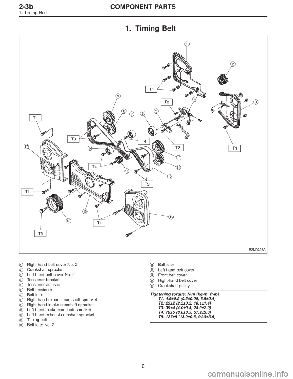
1. Timing Belt
B2M0726A
�1Right-hand belt cover No. 2
�
2Crankshaft sprocket
�
3Left-hand belt cover No. 2
�
4Tensioner bracket
�
5Tensioner adjuster
�
6Belt tensioner
�
7Belt idler
�
8Right-hand exhaust camshaft sprocket
�
9Right-hand intake camshaft sprocket
�
10Left-hand intake camshaft sprocket
�
11Left-hand exhaust camshaft sprocket
�
12Timing belt
�
13Belt idler No. 2�
14Belt idler
�
15Left-hand belt cover
�
16Front belt cover
�
17Right-hand belt cover
�
18Crankshaft pulley
Tightening torque: N⋅m (kg-m, ft-lb)
T1: 4.9±0.5 (0.5±0.05, 3.6±0.4)
T2: 25±2 (2.5±0.2, 18.1±1.4)
T3: 39±4 (4.0±0.4, 28.9±2.9)
T4: 78±5 (8.0±0.5, 57.9±3.6)
T5: 127±5 (13.0±0.5, 94.0±3.6)
6
2-3bCOMPONENT PARTS
1. Timing Belt
Page 399 of 2890
G2M0709
1. General Precautions
1) Before disassembling engine, place it on ST3.
ST1 498457000 ENGINE STAND ADAPTER RH
ST2 498457100 ENGINE STAND ADAPTER LH
ST3 499817000 ENGINE STAND
2) All parts should be thoroughly cleaned, paying special
attention to the engine oil passages, pistons and bearings.
3) Rotating parts and sliding parts such as piston, bearing
and gear should be coated with oil prior to assembly.
4) Be careful not to let oil, grease or coolant contact the
timing belt, clutch disc and flywheel.
5) All removed parts, if to be reused, should be reinstalled
in the original positions and directions.
6) Gaskets and lock washers must be replaced with new
ones. Liquid gasket should be used where specified to
prevent leakage.
7) Bolts, nuts and washers should be replaced with new
ones as required.
8) Even if necessary inspections have been made in
advance, proceed with assembly work while making
rechecks.
11
2-3bSERVICE PROCEDURE
1. General Precautions
Page 400 of 2890
2. Timing Belt
A: REMOVAL
1. CRANKSHAFT PULLEY AND BELT COVER
B2M0684A
G2M0711
1) Remove V-belt cover, V-belt and air conditioning com-
pressor drive belt tensioner.
2) Remove pulley bolt. To lock crankshaft, use ST.
ST 499977000 CRANKSHAFT PULLEY WRENCH
3) Remove crankshaft pulley.
B2M0729
4) Remove left-hand belt cover.
12
2-3bSERVICE PROCEDURE
2. Timing Belt
Page 401 of 2890
B2M0730
5) Remove right-hand belt cover.
B2M0731
6) Remove front belt cover.
13
2-3bSERVICE PROCEDURE
2. Timing Belt
Page 402 of 2890
2. TIMING BELT
B2M0685A
G2M0713
B2M0686A
1) If alignment mark and/or arrow mark (which indicates
rotation direction) on timing belt fade away, put new marks
before removing timing belt as follows:
(1) Turn crankshaft using ST, and align alignment
marks on crankshaft sprocket, left-hand intake cam-
shaft sprocket, left-hand exhaust camshaft sprocket,
right-hand intake camshaft sprocket and right hand
exhaust camshaft sprocket with notches of belt cover
and cylinder block.
ST 499987500 CRANKSHAFT SOCKET
14
2-3bSERVICE PROCEDURE
2. Timing Belt
Page 403 of 2890
B2M0687A
(2) Using white paint, put alignment and/or arrow
marks on timing belts in relation to the sprockets.
Z
1: 54.5 tooth length
Z
2: 51 tooth length
Z
3: 28 tooth length
B2M0688
B2M0689
G2M0739
2) Loosen tensioner adjuster mounting bolts.
3) Remove belt idler.
B2M0733
4) Remove timing belt.
5) Remove belt idler No. 2.
CAUTION:
After timing belt has been removed, never rotate intake
and exhaust, camshaft sprocket.
If camshaft sprocket is rotated, the intake and exhaust
valve heads strike together and valve stems are bent.
15
2-3bSERVICE PROCEDURE
2. Timing Belt
Page 404 of 2890
3. BELT TENSIONER AND IDLER
B2M0690A
B2M0732
1) Remove belt idler.
B2M0733
2) Remove belt idler No. 2.
B2M0734
3) Remove belt tensioner and spacer.
16
2-3bSERVICE PROCEDURE
2. Timing Belt

 Before disassembling engine, place it on ST3.
ST1 498457000 ENGINE STAND ADAPTER RH
ST2 498457100 ENGINE STAND ADAPTER LH
ST3 499817000 ENGINE STAND
2) All parts shou")
![SUBARU LEGACY 1996 Service Repair Manual 2. Timing Belt
A: REMOVAL
1. CRANKSHAFT PULLEY AND BELT COVER
B2M0684A
G2M0711
1) Remove V-belt cover, V-belt and air conditioning com-
pressor drive belt tensioner. <Ref. to 1-5 [01A0].>
2) Remove pu](/manual-img/17/57433/w960_57433-399.png "SUBARU LEGACY 1996 Service Repair Manual 2. Timing Belt
A: REMOVAL
1. CRANKSHAFT PULLEY AND BELT COVER
B2M0684A
G2M0711
1) Remove V-belt cover, V-belt and air conditioning com-
pressor drive belt tensioner. <Ref. to 1-5 [01A0].>
2) Remove pu")
 Remove right-hand belt cover.
B2M0731
6) Remove front belt cover.
13
2-3bSERVICE PROCEDURE
2. Timing Belt")
 If alignment mark and/or arrow mark (which indicates
rotation direction) on timing belt fade away, put new marks
before removing timing belt as follows:
(1)")
 Using white paint, put alignment and/or arrow
marks on timing belts in relation to the sprockets.
Z
1: 54.5 tooth length
Z
2: 51 tooth length
Z
3: 28 tooth length
B2M0688
B2M0689
G2M0739")
 Remove belt idler.
B2M0733
2) Remove belt idler No. 2.
B2M0734
3) Remove belt tensioner and spacer.
16
2-3bSERVICE PROCEDURE
2. Timing Belt")