Page 1635 of 1954

Driving Positio n Memor y Syste m (DPMS )
Steering Colum n Contro l Uni t Inpu t Tes t (cont'd )
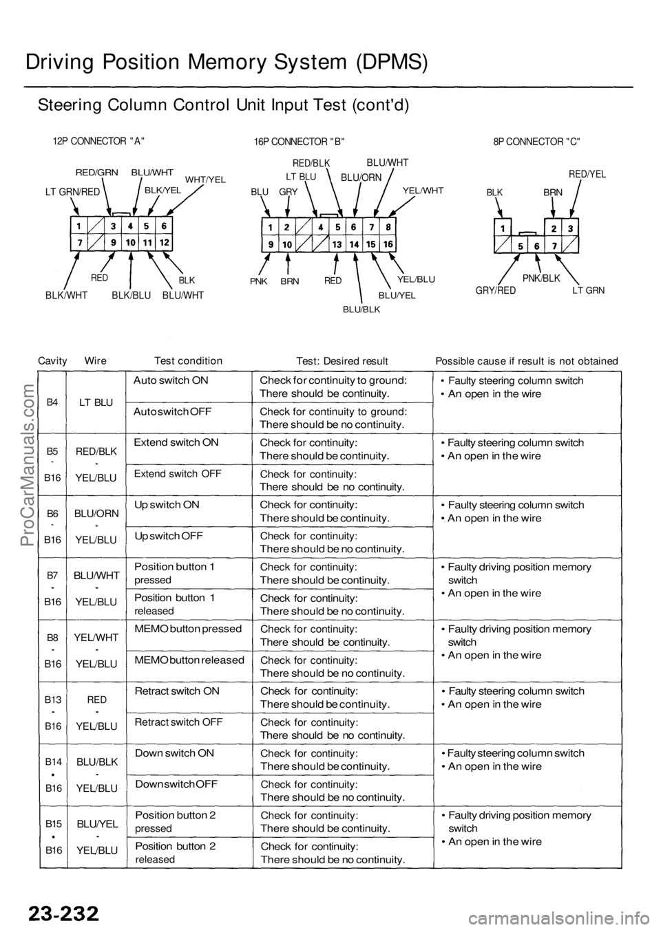
12P CONNECTO R "A "
RED/GR N BLU/WH TWHT/YELBLK/YEL
PNK BR NREDYEL/BL U
BLU/YE L
BLU/BLK
8P CONNECTO R "C "
RED/YE L
BLKBR N
GRY/RE DLT GR N
Cavit y Wir eTest conditio nTest: Desire d resul tPossibl e caus e if resul t i s no t obtaine d
B4
B5*
B1 6
B6*
B1 6
B7•
B1 6
B8•
B1 6
B1 3•
B16
B1 4
B16
B15
B16
LT BL U
RED/BL K•
YEL/BLU
BLU/OR N•
YEL/BLU
BLU/WH T•
YEL/BLU
YEL/WH T•
YEL/BLU
RED•
YEL/BL U
BLU/BL K•
YEL/BL U
BLU/YEL•
YEL/BLU
Auto switc h O N
Aut o switc h OF F
Exten d switc h O N
Exten d switc h OF F
Up switc h O N
U p switc h OF F
Positio n butto n 1
presse d
Position butto n 1
release d
MEMO butto n presse d
MEM O butto n release d
Retrac t switc h O N
Retrac t switc h OF F
Dow n switc h O N
Dow n switc h OF F
Positio n butto n 2
presse d
Position butto n 2
release d
Check fo r continuit y to ground :
Ther e shoul d b e continuity .
Check fo r continuit y t o ground :
There shoul d b e n o continuity .
Chec k fo r continuity :
Ther e shoul d b e continuity .
Check fo r continuity :
There shoul d b e n o continuity .
Chec k fo r continuity :
Ther e shoul d b e continuity .
Check fo r continuity :
There shoul d b e n o continuity .
Check fo r continuity :
There shoul d b e continuity .
Chec k fo r continuity :
Ther e shoul d b e n o continuity .
Check fo r continuity :
There shoul d b e continuity .
Check fo r continuity :
There shoul d b e n o continuity .
Chec k fo r continuity :
Ther e shoul d b e continuity .
Check fo r continuity :
There shoul d b e n o continuity .
Check fo r continuity :
There shoul d b e continuity .
Check fo r continuity :
There shoul d b e n o continuity .
Check fo r continuity :
There shoul d b e continuity .
Chec k fo r continuity :
Ther e shoul d b e n o continuity .
• Fault y steerin g colum n switc h
• A n ope n in th e wir e
• Fault y steerin g colum n switc h
• A n ope n in th e wir e
• Fault y steerin g colum n switc h
• A n ope n in th e wir e
• Fault y drivin g positio n memor y
switch
• A n ope n in th e wir e
• Fault y drivin g positio n memor y
switc h
• A n ope n in th e wir e
• Fault y steerin g colum n switc h
• A n ope n in th e wir e
• Fault y steerin g colum n switc h
• A n ope n in th e wir e
• Fault y drivin g positio n memor y
switch
• A n ope n in th e wir e
16P CONNECTO R "B "
RED/BL K
BLU GR Y
LT BL UBLU/OR N
BLU/WH
T
YEL/WHT
PNK/BLK
BLK/WH T BLK/BL U BLU/WH TBLKRE D
LT GRN/RE D
ProCarManuals.com
Page 1636 of 1954

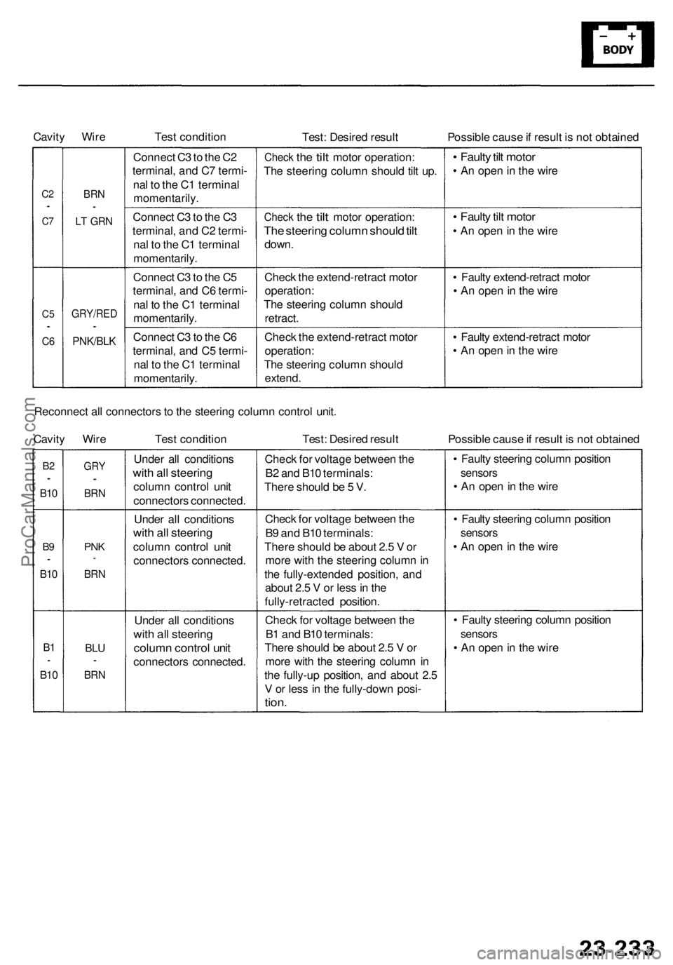
Cavity Wire
Test condition
Test: Desired result
Possible cause if result is not obtained
C2
•
C7
C5
•
C6
BRN
•
LT GRN
GRY/RED
•
PNK/BLK
Connect C3 to the C2
terminal, and C7 termi-
nal to the C1 terminal
momentarily.
Connect C3 to the C3
terminal, and C2 termi-
nal to the C1 terminal
momentarily.
Connect C3 to the C5
terminal, and C6 termi-
nal to the C1 terminal
momentarily.
Connect C3 to the C6
terminal, and C5 termi-
nal to the C1 terminal
momentarily.
Check
the
tilt
motor operation:
The steering column should tilt up.
Check
the
tilt
motor operation:
The steering column should tilt
down.
Check the extend-retract motor
operation:
The steering column should
retract.
Check the extend-retract motor
operation:
The steering column should
extend.
• Faulty tilt motor
• An open in the wire
• Faulty tilt motor
• An open in the wire
• Faulty extend-retract motor
• An open in the wire
• Faulty extend-retract motor
• An open in the wire
Reconnect all connectors to the steering column control unit.
Cavity Wire
Test condition
Test: Desired result
Possible cause if result is not obtained
B2
•
B10
B9
•
B10
B1
•
B10
GRY
•
BRN
PNK
*
BRN
BLU
•
BRN
Under all conditions
with all steering
column control unit
connectors connected.
Under all conditions
with all steering
column control unit
connectors connected.
Under all conditions
with all steering
column control unit
connectors connected.
Check for voltage between the
B2 and B10 terminals:
There should be 5 V.
Check for voltage between the
B9 and B10 terminals:
There should be about 2.5 V or
more with the steering column in
the fully-extended position, and
about 2.5 V or less in the
fully-retracted position.
Check for voltage between the
B1 and B10 terminals:
There should be about 2.5 V or
more with the steering column in
the fully-up position, and about 2.5
V or less in the fully-down posi-
tion.
• Faulty steering column position
sensors
• An open in the wire
• Faulty steering column position
sensors
• An open in the wire
• Faulty steering column position
sensors
• An open in the wireProCarManuals.com
Page 1803 of 1954

Precautions/Procedures
Steering-related Precaution s
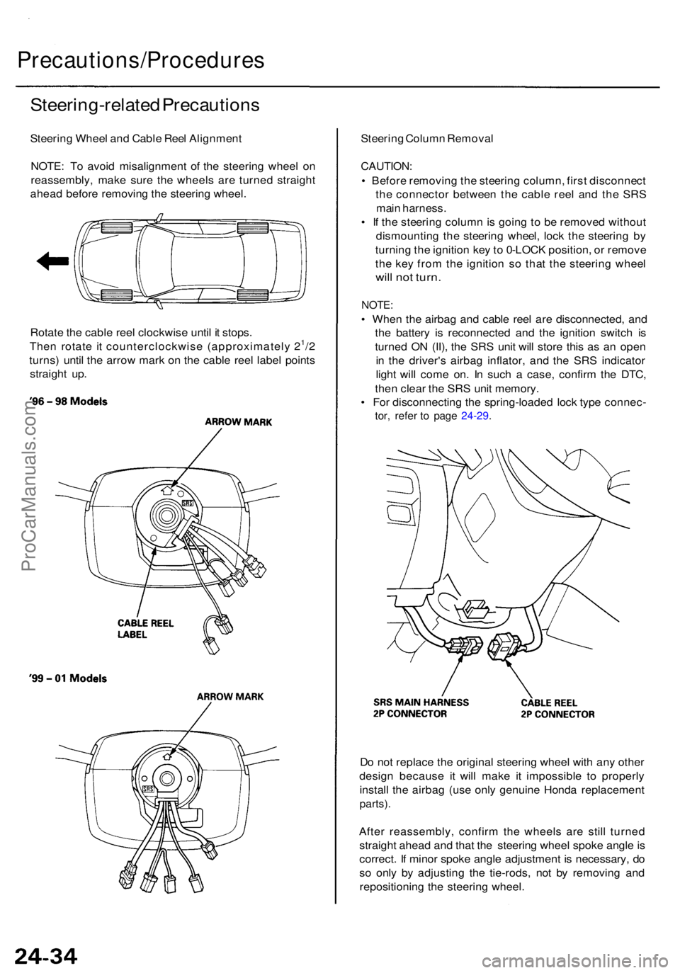
Steering Whee l an d Cabl e Ree l Alignmen t
NOTE : T o avoi d misalignmen t o f th e steerin g whee l o n
reassembly , mak e sur e th e wheel s ar e turne d straigh t
ahea d befor e removin g th e steerin g wheel .
Rotat e th e cabl e ree l clockwis e unti l i t stops .
The n rotat e i t counterclockwis e (approximatel y 2
1/2
turns ) unti l th e arro w mar k o n th e cabl e ree l labe l point s
straigh t up . Steerin
g Colum n Remova l
CAUTION :
• Befor e removin g th e steerin g column , firs t disconnec t
th e connecto r betwee n th e cabl e ree l an d th e SR S
mai n harness .
• I f th e steerin g colum n is goin g to b e remove d withou t
dismountin g th e steerin g wheel , loc k th e steerin g b y
turnin g th e ignitio n ke y to 0-LOC K position , o r remov e
th e ke y fro m th e ignitio n s o tha t th e steerin g whee l
will no t turn .
NOTE :
• Whe n th e airba g an d cabl e ree l ar e disconnected , an d
th e batter y i s reconnecte d an d th e ignitio n switc h i s
turne d O N (II) , th e SR S uni t wil l stor e thi s a s a n ope n
i n th e driver' s airba g inflator , an d th e SR S indicato r
ligh t wil l com e on . I n suc h a case , confir m th e DTC ,
the n clea r th e SR S uni t memory .
• Fo r disconnectin g th e spring-loade d loc k typ e connec -
tor, refe r t o pag e 24-29 .
Do no t replac e th e origina l steerin g whee l wit h an y othe r
desig n becaus e i t will mak e i t impossibl e t o properl y
instal l th e airba g (us e onl y genuin e Hond a replacemen t
parts).
After reassembly , confir m th e wheel s ar e stil l turne d
straigh t ahea d an d tha t th e steerin g whee l spok e angl e is
correct . I f mino r spok e angl e adjustmen t i s necessary , d o
s o onl y b y adjustin g th e tie-rods , no t b y removin g an d
repositionin g th e steerin g wheel .
ProCarManuals.com
Page 1933 of 1954
Airbag
Replacement (cont'd)
CAUTION: Be sure to install the SRS wiring so that it is
not pinched or interfering with other parts.
5. Install new airbag(s):
Driver's Side: Place the driver's airbag in the steering
wheel, and secure it with new Torx bolts.
'96-98 Models
Front Passenger's Side:
• Place the front passenger's airbag in the dashboard.
• Tighten the front passenger's airbag mounting nuts.
'99 - 01 ModelsProCarManuals.com
Page 1934 of 1954
6. Reconnect the airbag connector(s):
Front Passenger's Airbag:
• Connect the front passenger's airbag connector to
the SRS main harness connector, then install the
glove box.
Driver's Side:
• Connect the driver's airbag 2P connector to the cable
reel 2P connector, then install the access panel on the
steering wheel.
'96 - 98 Models
7. Reconnect the battery positive cable, then connect
the negative cable.
8. After installing the airbag, confirm proper system
operation:
• Turn the ignition switch ON (II); the SRS indica-
tor light should come on for about 6 seconds and
then go off.
• Make sure horn button works.
• Take a test drive, and make sure the cruise con-
trol switches work.
9. Enter the anti-theft code for the radio, then enter the
customer's radio station presets.
'99 - 01 ModelsProCarManuals.com
Page 1948 of 1954
'99-01 Models
'99 - 01 Models
8. Remove the steering wheel using a commercially
available steering wheel puller.
'96 - 98 Models
'99 - 01 Model
9. Remove the steering column covers.
'96 - 98 ModelsProCarManuals.com
Page 1949 of 1954

11. Remove the cable reel from the column.
13. Carefully install the cable reel on the steering col-
umn shaft. Then connect the 4P connector to the
cable reel, and connect the 2P connector to the SRS
main harness, then attach the cable reel 2P connec-
tor to the connector holder.
'96-98 Models
'99 - 01 Models
CAUTION:
• Before installing the steering wheel, the front
wheels should be aligned straight ahead.
• Be sure to install the harness wires so that they
are not pinched or interfering with other vehicle
parts.
• After reassembly, confirm that the wheels are
still turned straight ahead and that the steering
wheel spoke angle is correct (road test). If minor
spoke angle adjustment is necessary, do so only
by adjusting the tie-rods, not by removing and
repositioning the steering wheel.
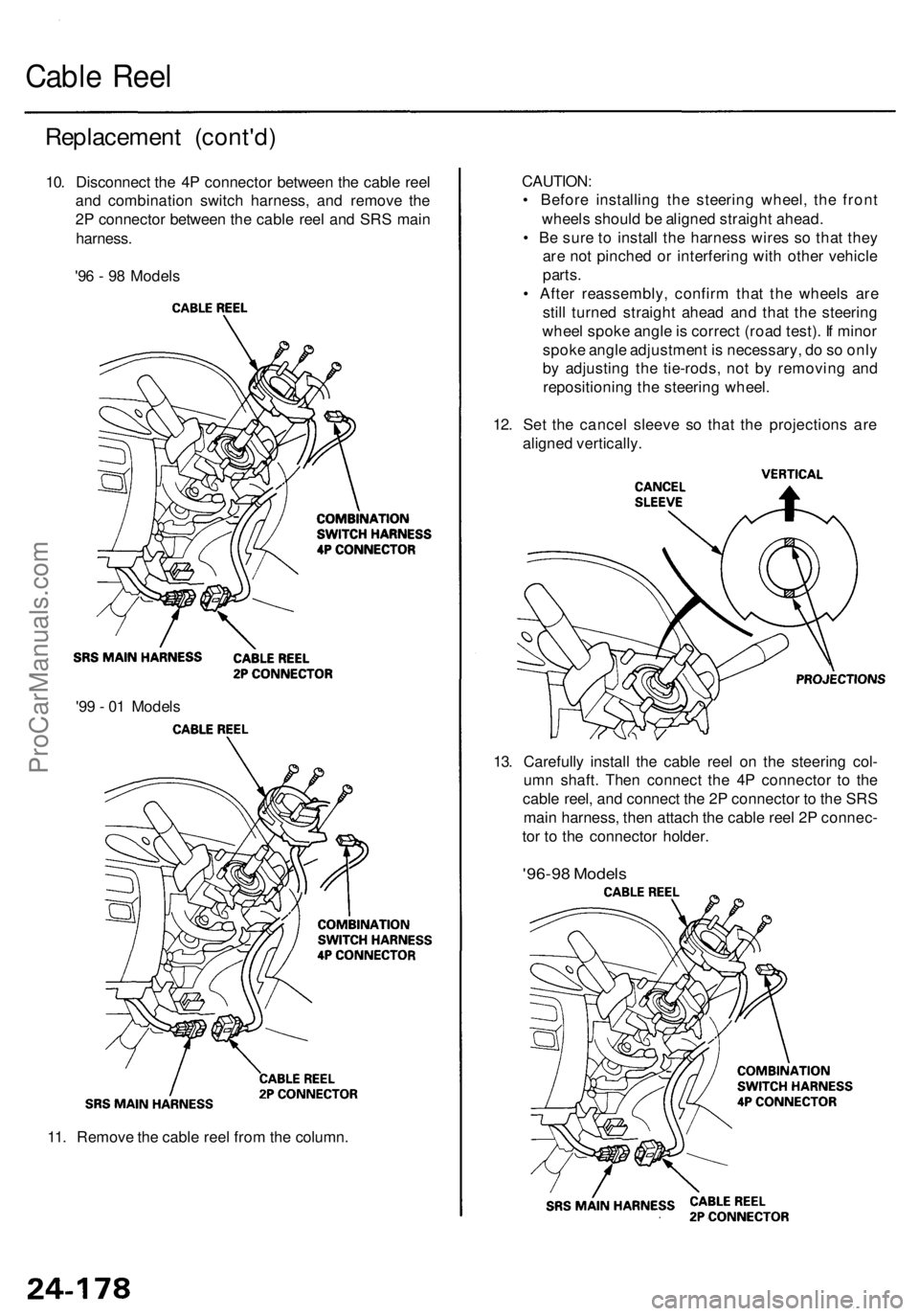
12. Set the cancel sleeve so that the projections are
aligned vertically.
Replacement (cont'd)
10. Disconnect the 4P connector between the cable reel
and combination switch harness, and remove the
2P connector between the cable reel and SRS main
harness.
'96 - 98 Models
Cable ReelProCarManuals.com
Page 1950 of 1954
'99 - 01 Models
'99 - 01 Models
16. Install the steering wheel, then connect the radio
remote switch connector, horn connector and cruise
control set/resume/cancel switch connector.
'96 - 98 Models
14. Install the steering column covers.
15. If necessary, center the cable reel. (New replace-
ment cable reels come centered.) Do this by first
rotating the cable reel clockwise until it stops. Then
rotate it counterclockwise (about 21/2 turns) until the
arrow mark on the cable reel label points straight
up.
'96 - 98 Models
'99 - 01 ModelsProCarManuals.com