1996 ACURA RL KA9 steering
[x] Cancel search: steeringPage 1547 of 1954

Headlights
Combinatio n Ligh t Switc h
Replacemen t
1. Remov e th e dashboar d lowe r cove r (se e sectio n 20 ).
2 . Remove the steering column covers (see
section 17 ).
3 . Disconnec t th e 14 P connecto r fro m th e combinatio n
ligh t switch , the n remov e th e tw o screw s an d th e
switch .
4 . Instal l th e combinatio n ligh t switc h i n th e revers e
orde r o f removal .
COMBINATIO N LIGH T SWITC H
14
P CONNECTO R
Replacemen t
CAUTION: Headlight s becom e ver y ho t i n use ; d o no t
touc h the m o r th e attachin g hardwar e immediatel y
afte r the y hav e bee n turne d off .
1 . Remov e th e fron t bumpe r an d fron t bumpe r uppe r
bea m (se e sectio n 20 ).
2 . Disconnec t th e connectors .
3 . Remov e th e fou r mountin g bolts , the n remov e th e
headligh t assembly .
HEADLIGH T
ASSEMBL Y
'9 6 - 9 8 models :
HEADLIGHT : 60/5 5 W
FRON T TUR N SIGNA L LIGHT : 2 1 W
FRON T PARKIN G LIGHT : 5 W x 2
FRON T FO G LIGHT : 5 5 W
SID E MARKE R LIGHT : 5 W
'9 9 - 0 1 models :
HEADLIGH T LO W BEAM : 3 5 W
HEADLIGH T HIG H BEAM : 5 5 W
FRON T TUR N SIGNAL/PARKIN G LIGHT : 27/ 8 W
SID E MARKE R LIGHT : 5 W
4. Instal l th e headligh t i n th e revers e orde r o f removal .
5 . Afte r replacement , adjus t th e headlight s t o loca l
requirements .
ProCarManuals.com
Page 1578 of 1954
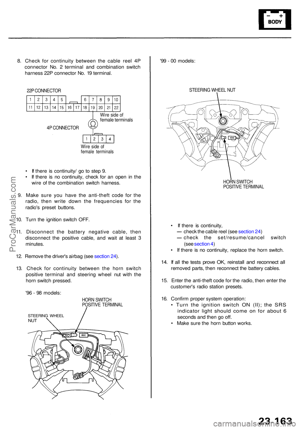
8. Chec k fo r continuit y betwee n th e cabl e ree l 4 P
connecto r No . 2 termina l an d combinatio n switc h
harnes s 22 P connecto r No . 1 9 terminal .
22P CONNECTO R
4 P CONNECTO R
Wir e sid e o f
femal e terminal s
Wir
e sid e o f
femal e terminal s
• I f ther e i s continuity / g o t o ste p 9 .
• I f ther e i s n o continuity , chec k fo r a n ope n i n th e
wir e o f th e combinatio n switc h harness .
9 . Mak e sur e yo u hav e th e anti-thef t cod e fo r th e
radio , the n writ e dow n th e frequencie s fo r th e
radio' s prese t buttons .
10 . Tur n th e ignitio n switc h OFF .
11 . Disconnec t th e batter y negativ e cable , the n
disconnec t th e positiv e cable , an d wai t a t leas t 3
minutes .
12 . Remov e th e driver' s airba g (se e sectio n 24 ).
13 . Chec k fo r continuit y betwee n th e hor n switc h
positiv e termina l an d steerin g whee l nu t wit h th e
hor n switc h pressed .
HORN SWITC H
POSITIV E TERMINA L
STEERING WHEE LNUT
'96 - 9 8 models : '9
9 - 0 0 models :
STEERIN G WHEE L NU T
HOR N SWITC H
POSITIV E TERMINA L
• I f ther e i s continuity ,
chec k th e cabl e ree l (se e sectio n 24 )
chec k th e set/resume/cance l switc h
(se e sectio n 4 )
• I f ther e i s n o continuity , replac e th e hor n switch .
14. I f al l th e test s prov e OK , reinstal l an d reconnec t al l
remove d parts , the n reconnec t th e batter y cables .
15 . Ente r th e anti-thef t cod e fo r th e radio , the n ente r th e
customer' s radi o statio n presets .
16 . Confir m prope r syste m operation :
• Tur n th e ignitio n switc h O N (II) ; th e SR S
indicato r ligh t shoul d com e o n fo r abou t 6
second s an d the n g o off .
• Mak e sur e th e hor n butto n works .
ProCarManuals.com
Page 1602 of 1954
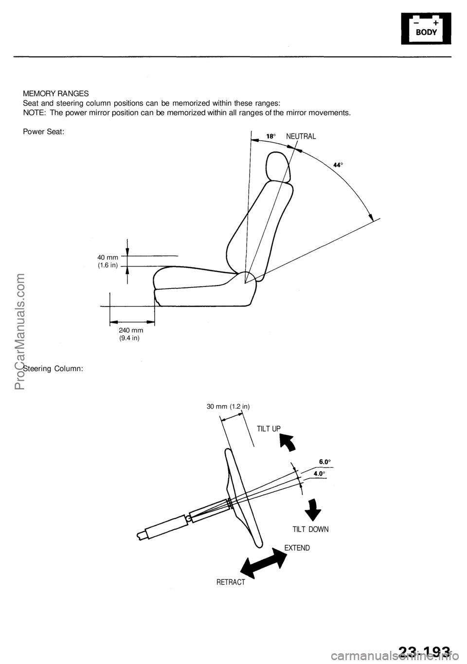
MEMORY RANGE S
Sea t an d steerin g colum n position s ca n b e memorize d withi n thes e ranges :
NOTE: Th e powe r mirro r positio n ca n b e memorize d withi n al l range s o f th e mirro r movements .
Power Seat :NEUTRA L
Steering Column :
240 m m(9. 4 in)
40 m m(1.6 in )
RETRAC T
EXTEND
TIL
T DOW N
TIL
T U P
30 m m (1. 2 in)
ProCarManuals.com
Page 1604 of 1954
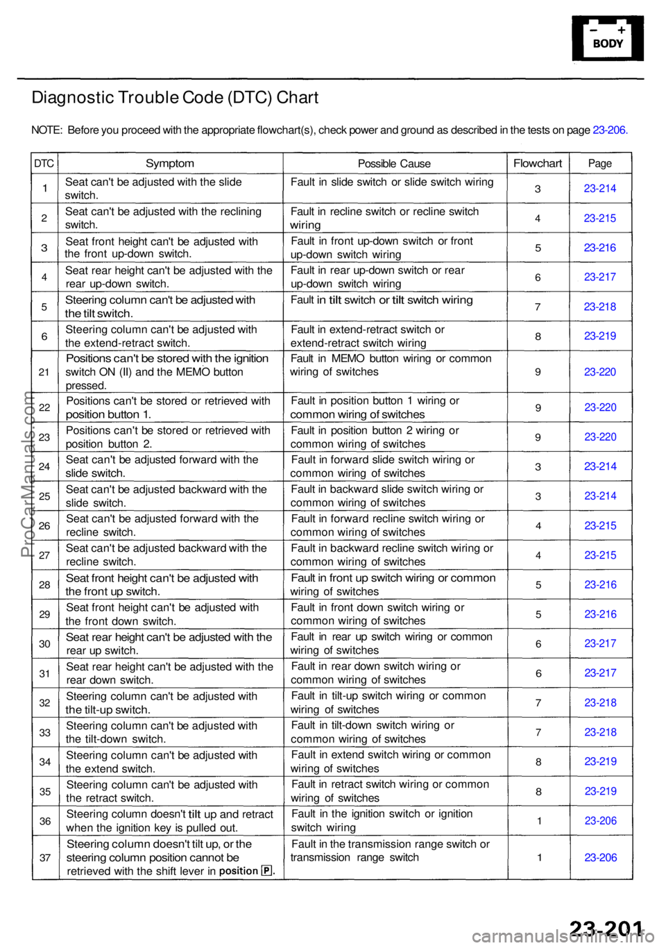
Diagnostic Troubl e Cod e (DTC ) Char t
NOTE : Befor e yo u procee d wit h th e appropriat e flowchart(s) , chec k powe r an d groun d a s describe d in th e test s o n pag e 23-206 .
DTC
1
2
3
4
5
6
21
22
23
2 4
25
26
27
2 8
2 9
30
3 1
3 2
33
3 4
35
36
37
Sympto m
Seat can' t b e adjuste d wit h th e slid e
switch .
Sea t can' t b e adjuste d wit h th e reclinin g
switch .
Sea t fron t heigh t can' t b e adjuste d wit h
th e fron t up-dow n switch .
Sea t rea r heigh t can' t b e adjuste d wit h th e
rea r up-dow n switch .
Steering colum n can' t b e adjuste d wit h
the til t switch .
Steerin g colum n can' t b e adjuste d wit h
th e extend-retrac t switch .
Position s can' t b e store d wit h th e ignitio n
switch O N (II ) an d th e MEM O butto n
pressed .
Positions can' t b e store d o r retrieve d wit h
positio n butto n 1 .
Position s can' t b e store d o r retrieve d wit h
positio n butto n 2 .
Sea t can' t b e adjuste d forwar d wit h th e
slid e switch .
Seat can' t b e adjuste d backwar d wit h th e
slid e switch .
Sea t can' t b e adjuste d forwar d wit h th e
reclin e switch .
Sea t can' t b e adjuste d backwar d wit h th e
reclin e switch .
Seat fron t heigh t can' t b e adjuste d wit h
the fron t u p switch .
Seat fron t heigh t can' t b e adjuste d wit h
th e fron t dow n switch .
Seat rea r heigh t can' t b e adjuste d wit h th e
rea r u p switch .
Sea t rea r heigh t can' t b e adjuste d wit h th e
rea r dow n switch .
Steerin g colum n can' t b e adjuste d wit h
the tilt-u p switch .
Steerin g colum n can' t b e adjuste d wit h
th e tilt-dow n switch .
Steerin g colum n can' t b e adjuste d wit h
th e exten d switch .
Steerin g colum n can' t b e adjuste d wit h
th e retrac t switch .
Steerin g colum n doesn' t
tilt up an d retrac t
whe n th e ignitio n ke y i s pulle d out .
Steerin g colum n doesn' t til t up , o r th e
steerin g colum n positio n canno t b e
retrieve d wit h th e shif t leve r i n Possibl
e Caus e
Faul t i n slid e switc h o r slid e switc h wirin g
Faul t i n reclin e switc h o r reclin e switc h
wiring
Fault i n fron t up-dow n switc h o r fron t
up-dow n switc h wirin g
Faul t i n rea r up-dow n switc h o r rea r
up-dow n switc h wirin g
Faul t
in til t switc h or tilt switc h wiring
Fault i n extend-retrac t switc h o r
extend-retrac t switc h wirin g
Faul t i n MEM O butto n wirin g o r commo n
wirin g o f switche s
Faul t i n positio n butto n 1 wirin g o r
commo n wirin g o f switche s
Fault i n positio n butto n 2 wirin g o r
commo n wirin g o f switche s
Faul t i n forwar d slid e switc h wirin g o r
commo n wirin g o f switche s
Faul t i n backwar d slid e switc h wirin g o r
commo n wirin g o f switche s
Faul t i n forwar d reclin e switc h wirin g o r
commo n wirin g o f switche s
Faul t i n backwar d reclin e switc h wirin g o r
commo n wirin g o f switche s
Fault i n fron t u p switc h wirin g o r commo n
wiring o f switche s
Faul t i n fron t dow n switc h wirin g o r
commo n wirin g o f switche s
Faul t i n rea r u p switc h wirin g o r commo n
wirin g o f switche s
Faul t i n rea r dow n switc h wirin g o r
commo n wirin g o f switche s
Faul t i n tilt-u p switc h wirin g o r commo n
wirin g o f switche s
Faul t i n tilt-dow n switc h wirin g o r
commo n wirin g o f switche s
Faul t i n exten d switc h wirin g o r commo n
wirin g o f switche s
Faul t i n retrac t switc h wirin g o r commo n
wirin g o f switche s
Faul t i n th e ignitio n switc h o r ignitio n
switc h wirin g
Faul t i n th e transmissio n rang e switc h o r
transmissio n rang e switc h
Flowchar t
3
4
5
6
7
8
9
9
9
3
3
4
4
5
5
6
6
7
7
8
8
1
1
Pag e
23-21 4
23-215
23-216
23-21 7
23-218
23-21 9
23-22 0
23-22 0
23-22 0
23-214
23-21 4
23-215
23-21 5
23-21 6
23-216
23-217
23-217
23-21 8
23-218
23-219
23-21 9
23-20 6
23-206
ProCarManuals.com
Page 1608 of 1954
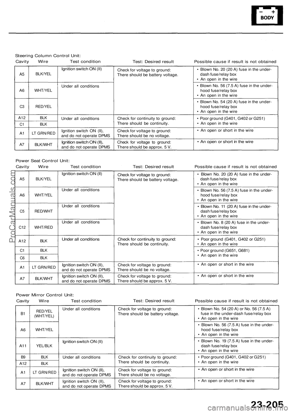
Steering Colum n Contro l Unit :
Cavit y Wir e Tes t conditio nTest: Desire d resul tPossibl e caus e if resul t i s no t obtaine d
A5
A 6
C 3
A1 2
C1
A1
A7
BLK/YE L
WHT/YE L
RED/YEL
BLK
BL K
LT GRN/RE D
BLK/WHT
Ignition switc h O N (II )
Unde r al l condition s
Unde r al l condition s
Ignitio n switc h O N (II) ,
an d d o no t operat e DPM S
Ignition switc h O N (II) ,and d o no t operat e DPM SChec
k fo r voltag e t o ground :
Ther e shoul d b e batter y voltage .
Chec k fo r continuit y t o ground :
Ther e shoul d b e continuity .
Chec k fo r voltag e to ground :
Ther e shoul d b e n o voltage .
Chec k fo r voltag e t o ground :
Ther e shoul d b e approx . 5 V . •
Blow n No . 2 0 (2 0 A ) fus e in th e under -
das h fuse/rela y bo x
• A n ope n i n th e wire
• Blow n No . 5 6 (7. 5 A ) fus e in th e under -
hoo d fuse/rela y bo x
• A n ope n in th e wir e
• Blow n No . 5 4 (2 0 A ) fus e in th e under -
hoo d fuse/rela y bo x
• A n ope n i n th e wir e
• Poo r groun d (G401 , G40 2 o r G251 )
• A n ope n in th e wir e
• A n ope n o r shor t i n th e wir e
• A n ope n o r shor t i n th e wir e
Powe r Sea t Contro l Unit :
Cavit y Wir e Tes t conditio nTest: Desire d resul tPossibl e caus e if resul t i s no t obtaine d
A5
A6
C 5
C1 2
A12
C1
C 6
A1
A 7
BLK/YE L
WHT/YE L
RED/WH T
WHT/RED
BLK
BL K
BL K
LT GRN/RE D
BLK/WHT
Ignition switc h O N (II )
Unde r al l condition s
Unde r al l condition s
Unde r al l condition s
Under al l condition s
Ignition switc h O N (II) ,and d o no t operat e DPM S
Ignitio n switc h O N (II) ,and d o no t operat e DPM S
Check fo r voltag e to ground :There shoul d b e batter y voltage .
Check fo r continuit y t o ground :There shoul d b e continuity .
Chec k fo r voltag e t o ground :
Ther e shoul d b e n o voltage .
Chec k fo r voltag e t o ground :
Ther e shoul d b e approx . 5 V . •
Blow n No . 2 0 (2 0 A ) fus e in th e under -
das h fuse/rela y bo x
• A n ope n in th e wir e
• Blow n No . 5 6 (7. 5 A ) fus e in th e under -
hoo d fuse/rela y bo x
• A n ope n i n th e wire
• Blow n No . 1 1 (2 0 A ) fus e in th e under -dash fuse/rela y bo x
• A n ope n i n th e wir e
• Blow n No . 8 (2 0 A ) fus e in th e under -
das h fuse/rela y bo x
• A n ope n in th e wir e
• Poo r groun d (G401 , G40 2 o r G251 )
• A n ope n in th e wir e
• Poo r groun d (G651 , G681 )
• A n ope n in th e wir e
• A n ope n o r shor t i n th e wir e
• A n ope n o r shor t i n th e wir e
Powe r Mirro r Contro l Unit :
Cavit y Wir e Tes t conditio nTest: Desire d resul tPossibl e caus e if resul t i s no t obtaine d
B1
A 6
A1 1
B9
A1 2
A1
A7
RED/YE L(WHT/YEL )
WHT/YEL
YEL/BLK
BLK
BLK
LT GRN/RE D
BLK/WHT
Under al l condition s
Ignition switc h O N (II )
Unde r al l condition s
Ignition switc h O N (II) ,and d o no t operat e DPM S
Ignitio n switc h O N (II) ,
an d d o no t operat e DPM SChec
k fo r voltag e t o ground :
Ther e shoul d b e batter y voltage .
Chec k fo r continuit y t o ground :
Ther e shoul d b e continuity .
Chec k fo r voltag e t o ground :
Ther e shoul d b e n o voltage .
Chec k fo r voltag e t o ground :
Ther e shoul d b e approx . 5 V . •
Blow n No . 5 4 (2 0 A ) o r No . 5 6 (7. 5 A )
fus e in th e under-das h fuse/rela y bo x
• A n ope n in th e wir e
• Blow n No . 5 6 (7. 5 A ) fus e in th e under -
hoo d fuse/rela y bo x
• A n ope n in th e wire
• Blow n No . 1 9 (7. 5 A ) fus e in th e under -
das h fuse/rela y bo x
• A n ope n in th e wir e
• Poo r groun d (G401 , G40 2 o r G251 )
• A n ope n i n th e wir e
• A n ope n o r shor t i n th e wir e
• A n ope n o r shor t i n th e wir e
ProCarManuals.com
Page 1628 of 1954
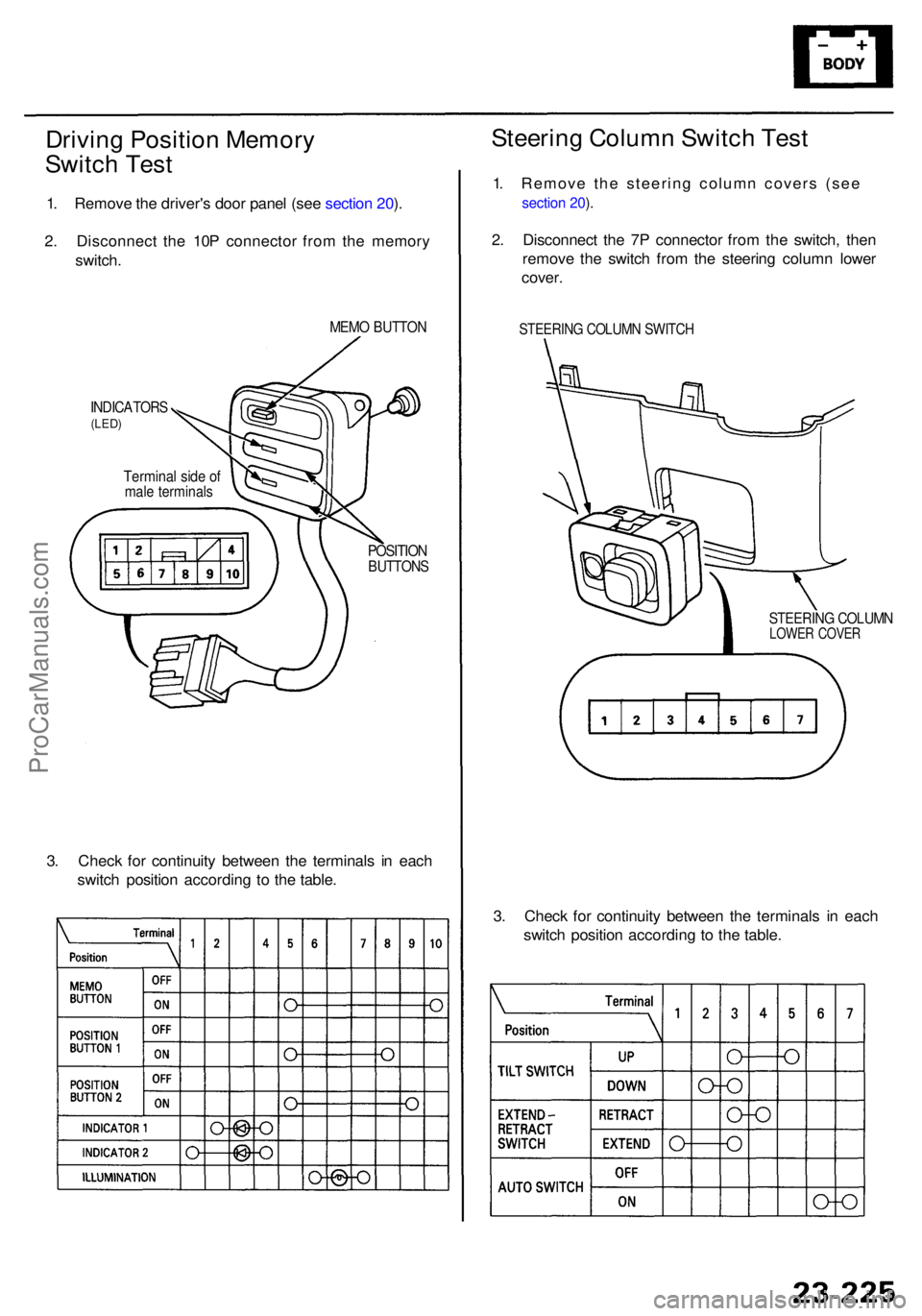
Driving Positio n Memor y
Switc h Tes t
1. Remov e th e driver' s doo r pane l (se e sectio n 20 ).
2 . Disconnec t th e 10 P connecto r fro m th e memor y
switch .
MEMO BUTTO N
INDICATOR S(LED)
Termina l sid e o fmal e terminal s
POSITIONBUTTON S
3. Chec k fo r continuit y betwee n th e terminal s i n eac h
switc h positio n accordin g t o th e table .
3. Chec k fo r continuit y betwee n th e terminal s i n eac h
switc h positio n accordin g t o th e table .
Steerin g Colum n Switc h Tes t
1. Remove the steering column covers (see
section 20 ).
2 . Disconnec t th e 7 P connecto r fro m th e switch , the n
remov e th e switc h fro m th e steerin g colum n lowe r
cover .
STEERIN G COLUM N SWITC H
STEERIN G COLUM NLOWER COVE R
ProCarManuals.com
Page 1629 of 1954
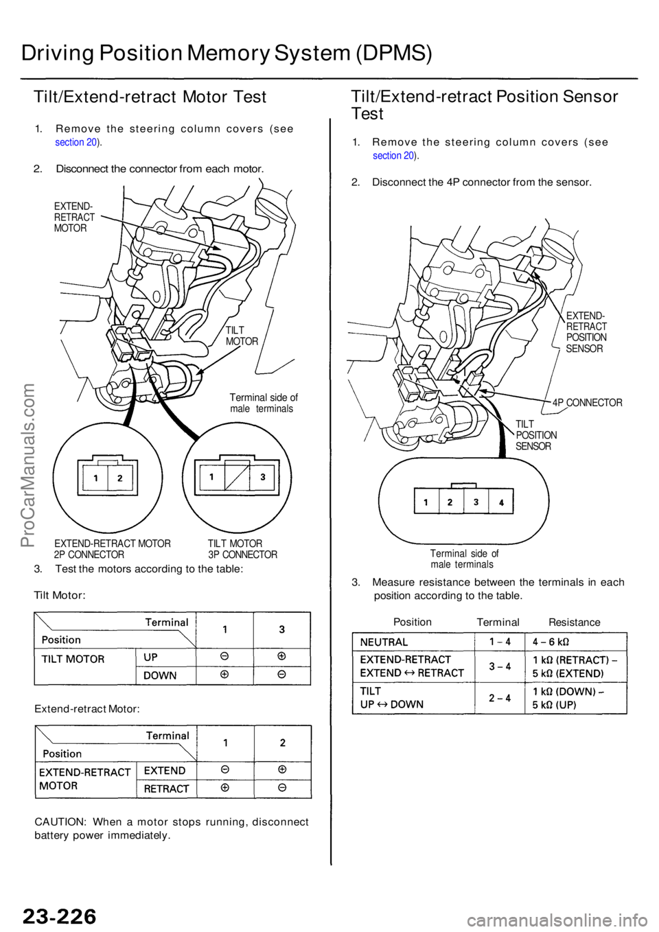
Driving Positio n Memor y Syste m (DPMS )
Tilt/Extend-retrac t Moto r Tes t
1. Remove the steering column covers (see
section 20 ).
2 . Disconnec t th e connecto r fro m eac h motor .
EXTEND -RETRAC TMOTOR
EXTEND-RETRAC T MOTO R TIL T MOTO R
2 P CONNECTO R 3 P CONNECTO R
3. Tes t th e motor s accordin g t o th e table :
Tilt Motor :
Extend-retrac t Motor :
CAUTION : Whe n a moto r stop s running , disconnec t
batter y powe r immediately .
Tilt/Extend-retrac t Positio n Senso r
Test
1. Remove the steering column covers (see
section 20 ).
2 . Disconnec t th e 4 P connecto r fro m th e sensor .
EXTEND -RETRAC TPOSITION
SENSO R
4 P CONNECTO R
Termina l sid e o f
mal e terminal s
3. Measur e resistanc e betwee n th e terminal s i n eac h
positio n accordin g t o th e table .
Positio nTermina lResistanc e
Terminal sid e o fmal e terminal s
TIL
T
MOTO R
TILT
POSITIO N
SENSO R
ProCarManuals.com
Page 1633 of 1954
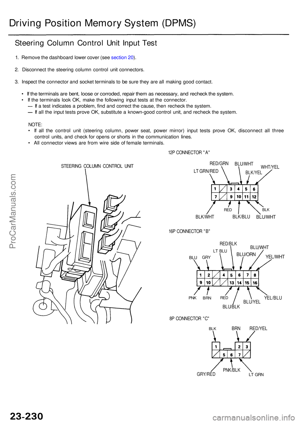
Driving Positio n Memor y Syste m (DPMS )
Steering Colum n Contro l Uni t Inpu t Tes t
1. Remov e th e dashboar d lowe r cove r (se e sectio n 20 ).
2 . Disconnec t th e steerin g colum n contro l uni t connectors .
3 . Inspec t th e connecto r an d socke t terminal s t o b e sur e the y ar e al l makin g goo d contact .
• I f th e terminal s ar e bent , loos e o r corroded , repai r the m as necessary , an d rechec k th e system .
• I f th e terminal s loo k OK , mak e th e followin g inpu t test s a t th e connector .
I f a tes t indicate s a problem , fin d an d correc t th e cause , the n rechec k th e system .
If al l th e inpu t test s prov e OK , substitut e a known-goo d contro l unit , an d rechec k th e system .
NOTE:
• I f al l th e contro l uni t (steerin g column , powe r seat , powe r mirror ) inpu t test s prov e OK , disconnec t al l thre e
contro l units , an d chec k fo r open s o r short s i n th e communicatio n lines .
• Al l connecto r view s ar e fro m wir e sid e o f femal e terminals .
STEERING COLUM N CONTRO L UNI T 12
P CONNECTO R "A "
BLK/WH T
BLK/BLUBLU/WH T
BLKRE D
WHT/YE L
RED/GR
N
BLU/WH T
BLK/YELLT GRN/RE D
16 P CONNECTO R "B "
BLUGR Y
LT BL U
RED/BL K
BLU/ORN
BLU/WH T
YEL/WHT
YEL/BLUBLU/YE LBLU/BLK
REDBR NPNK
8P CONNECTO R "C "
BLKBR N RED/YE L
LT GR NPNK/BL KGRY/RED
ProCarManuals.com