Page 994 of 1954

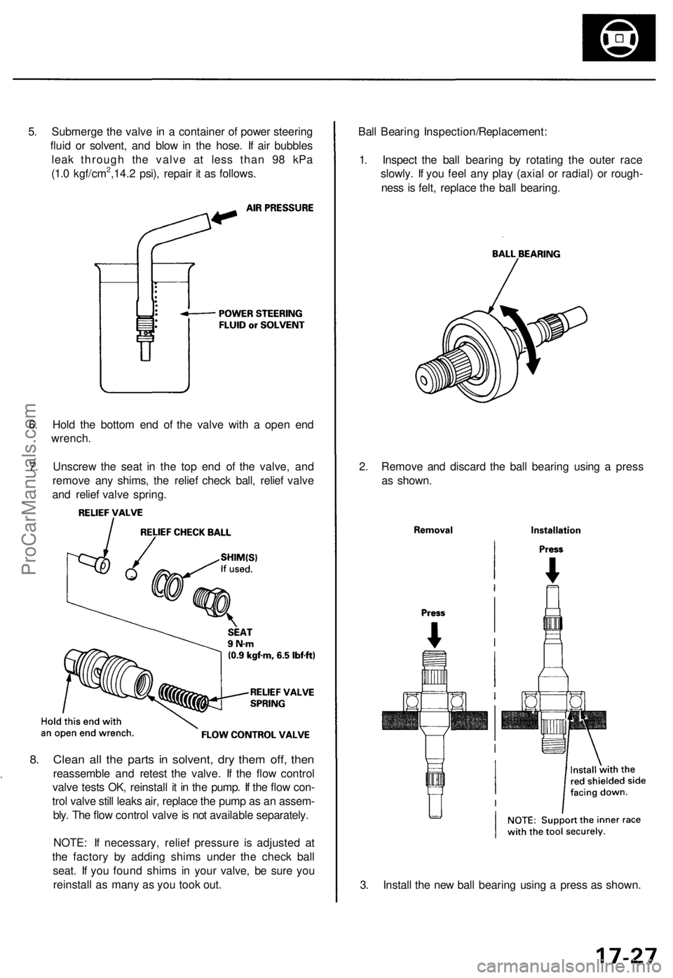
5. Submerge the valve in a container of power steering
fluid or solvent, and blow in the hose. If air bubbles
leak through the valve at less than 98 kPa
(1.0 kgf/cm2,14.2 psi), repair it as follows.
6. Hold the bottom end of the valve with a open end
wrench.
7. Unscrew the seat in the top end of the valve, and
remove any shims, the relief check ball, relief valve
and relief valve spring.
8. Clean all the parts in solvent, dry them off, then
reassemble and retest the valve. If the flow control
valve tests OK, reinstall it in the pump. If the flow con-
trol valve still leaks air, replace the pump as an assem-
bly. The flow control valve is not available separately.
NOTE: If necessary, relief pressure is adjusted at
the factory by adding shims under the check ball
seat. If you found shims in your valve, be sure you
reinstall as many as you took out.
3. Install the new ball bearing using a press as shown.
2. Remove and discard the ball bearing using a press
as shown.
Ball Bearing Inspection/Replacement:
1. Inspect the ball bearing by rotating the outer race
slowly. If you feel any play (axial or radial) or rough-
ness is felt, replace the ball bearing.ProCarManuals.com
Page 999 of 1954
8. Remove the steering joint bolts, then disconnect the
steering joint by moving the joint toward the column.
10. Disconnect the feed line from the valve body unit
upper side.
CAUTION: After disconnecting the feed line, plug or
seal the line fitting with a piece of tape or equivalent
to prevent foreign materials from entering the valve
body unit.
11. Remove the clamps from the line mounting cush-
ions, then remove the feed line from the cushions.
9. Remove the splash guard.ProCarManuals.com
Page 1000 of 1954
Power Steering Gearbox
Removal (cont'd)
12. Disconnect the three lines (sensor inlet line, 10 mm
return line and 6 mm return line) from the hoses.
CAUTION: After disconnecting the line, plug or
seal the line with a piece of tape or equivalent.
13. Remove the mounting brackets and steering gear-
box.
NOTE: Before removing the steering gearbox, place
a jack stand under the gearbox to support it.
CAUTION: Be careful not to bend or damage fluid
lines when removing the steering gearbox.ProCarManuals.com
Page 1001 of 1954
Disassembly
Steering Rac k Disassembl y
NOTE:
• Befor e disassemblin g th e gearbox , was h i t of f wit h
solven t an d a brush .
• D o no t di p seal s an d 0-ring s i n solvent .
1 . Remov e th e steerin g gearbo x (se e pag e 17-30 ).
2 . Remov e th e bot h tie-ro d ends .
3 . Remov e th e thre e line s (senso r inle t line , 1 0 m m
retur n lin e an d 6 m m retur n line ) fro m th e valv e bod y
unit.
4. Remov e th e lin e mountin g cushions .
Power Steerin g Gearbo x
ProCarManuals.com
Page 1002 of 1954
5. Remove the boot bands and tie-rod clips. Pull the
boots away from the ends of the gearbox.
6. Hold the steering rack with one wrench ('99 - 01
models: left end only), and unscrew the rack end with
another wrench.
NOTE: '96 - 98 models shown.
CAUTION: Be careful not to damage the rack sur-
face with the wrench.
7. Loosen the locknut, then remove the rack guide
screw and O-ring ('96 - 98 models only).
8. Remove the spring and rack guide from the gearbox
housing.
9. Remove cylinder lines A and B from the gearbox.
10. Drain the fluid from the cylinder fittings by slowly
moving the steering rack back and forth.ProCarManuals.com
Page 1018 of 1954
65. Install the new lock washer in the groove in the
steering rack.
66. Install the steering rack ends into the rack.
67. Hold the steering rack with a wrench ('99 - 01 mod-
els: left end only), and tighten the rack ends with
another wrench.
69. Apply steering grease to the circumference of the
rack end housing.
70. Apply a light coat of silicone grease to the boot
grooves on the rack ends.
71. Install the boots in the rack end with the tube clamps.
NOTE: Install the boots with the rack in the straight
ahead position (right and left tie-rods are equal in
length).
68. After tightening the rack ends, stake the four section
of lock washer with a commercially-available roll
pin drift and mallet.
• Place the wood block, then set the lock washer
section of rack end securely on the wood block.
• Be sure the tool is aligned with the stake point
(four dents) of the steering rack end before stak-
ing.ProCarManuals.com
Page 1026 of 1954

Wheel Alignment
Caster
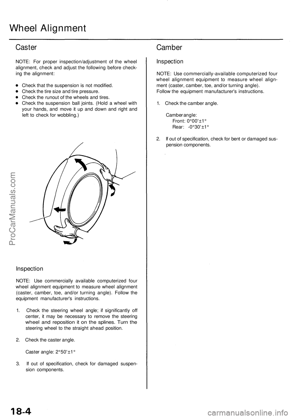
NOTE: For proper inspection/adjustment of the wheel
alignment, check and adjust the following before check-
ing the alignment:
Check that the suspension is not modified.
Check the tire size and tire pressure.
Check the runout of the wheels and tires.
Check the suspension ball joints. (Hold a wheel with
your hands, and move it up and down and right and
left to check for wobbling.)
Inspection
NOTE: Use commercially available computerized four
wheel alignment equipment to measure wheel alignment
(caster, camber, toe, and/or turning angle). Follow the
equipment manufacturer's instructions.
1. Check the steering wheel angle; if significantly off
center, it may be necessary to remove the steering
wheel and reposition it on the splines. Turn the
steering wheel to the straight ahead position.
2. Check the caster angle.
Caster angle: 2°50'±1°
3. If out of specification, check for damaged suspen-
sion components.
Camber
Inspection
NOTE: Use commercially-available computerized four
wheel alignment equipment to measure wheel align-
ment (caster, camber, toe, and/or turning angle).
Follow the equipment manufacturer's instructions.
1. Check the camber angle.
Camber angle:
Front: 0°00'±1°
Rear: -0°30'±1°
2. If out of specification, check for bent or damaged sus-
pension components.ProCarManuals.com
Page 1027 of 1954

Front Toe Inspection/Adjustment
NOTE: Use commercially-available computerized four
wheel alignment equipment to measure wheel align-
ment (caster, camber, toe, and/or turning angle).
Follow the equipment manufacturer's instructions.
1. Check the tire pressure.
2. Center the steering wheel spokes.
3. Check the toe with the wheels pointed straight
ahead.
Front toe: 0 ± 2 mm (0±1/16 in)
— If adjustment is required, go on to step 4.
— If no adjustment is required, remove the align-
ment equipment.
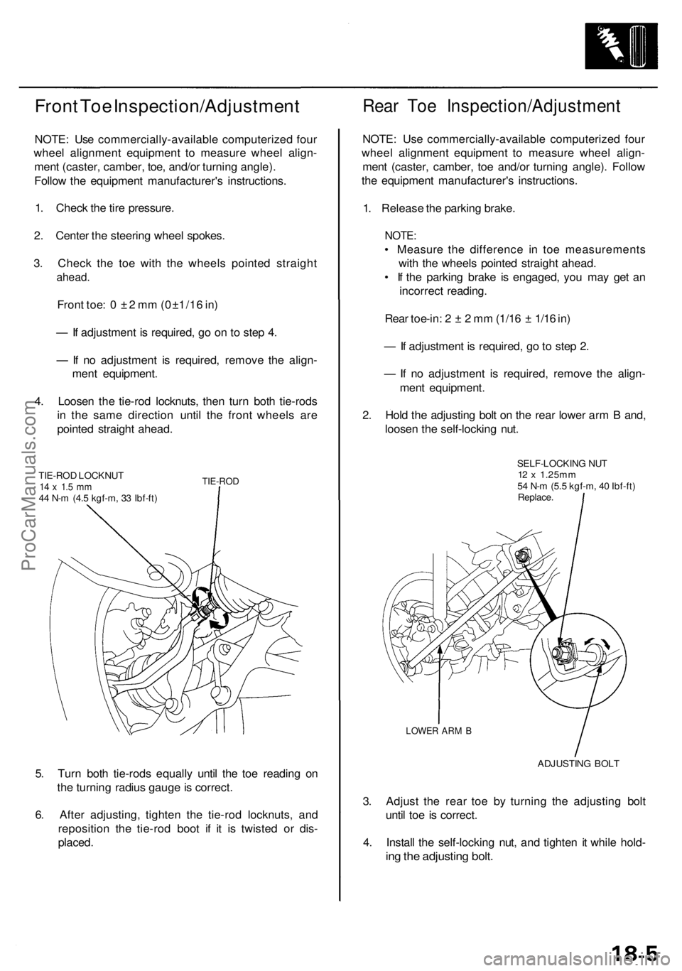
4. Loosen the tie-rod locknuts, then turn both tie-rods
in the same direction until the front wheels are
pointed straight ahead.
TIE-ROD LOCKNUT
14 x 1.5 mm
44 N-m (4.5 kgf-m, 33 Ibf-ft)
TIE-ROD
5. Turn both tie-rods equally until the toe reading on
the turning radius gauge is correct.
6. After adjusting, tighten the tie-rod locknuts, and
reposition the tie-rod boot if it is twisted or dis-
placed.
Rear Toe Inspection/Adjustment
NOTE: Use commercially-available computerized four
wheel alignment equipment to measure wheel align-
ment (caster, camber, toe and/or turning angle). Follow
the equipment manufacturer's instructions.
1. Release the parking brake.
NOTE:
• Measure the difference in toe measurements
with the wheels pointed straight ahead.
• If the parking brake is engaged, you may get an
incorrect reading.
Rear toe-in: 2 ± 2 mm (1/16 ± 1/16 in)
— If adjustment is required, go to step 2.
— If no adjustment is required, remove the align-
ment equipment.
2. Hold the adjusting bolt on the rear lower arm B and,
loosen the self-locking nut.
SELF-LOCKING NUT
12 x 1.25mm
54 N-m (5.5 kgf-m, 40 Ibf-ft)
Replace.
LOWER ARM B
ADJUSTING BOLT
3. Adjust the rear toe by turning the adjusting bolt
until toe is correct.
4. Install the self-locking nut, and tighten it while hold-
ing the adjusting bolt.ProCarManuals.com