Page 971 of 1954

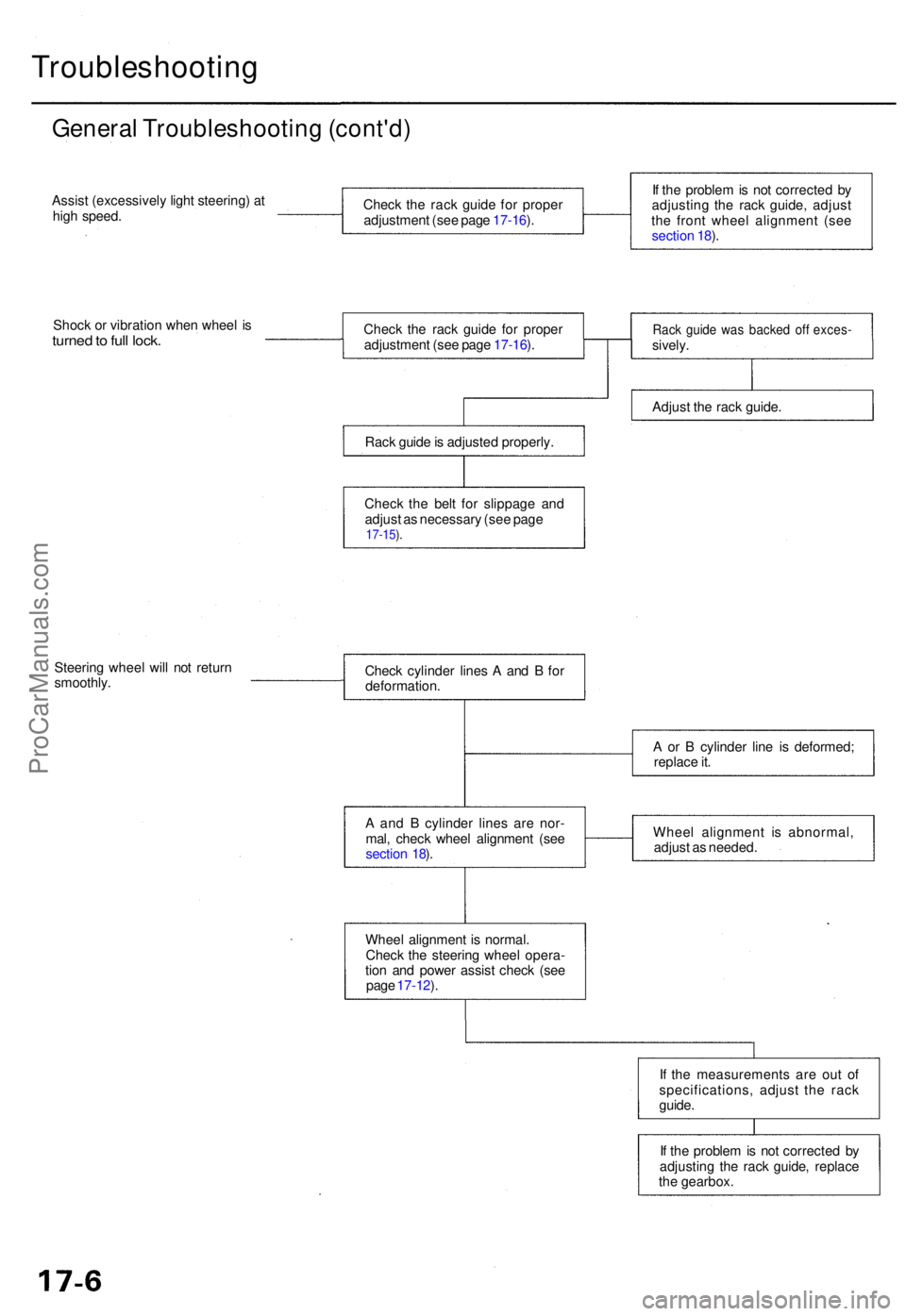
Troubleshooting
General Troubleshootin g (cont'd )
Assist (excessivel y ligh t steering ) a t
hig h speed .
Shoc k o r vibratio n whe n whee l i s
turne d to ful l lock .
Steerin g whee l wil l no t retur n
smoothly .
If th e proble m is no t correcte d b y
adjustin g th e rac k guide , replace
th e gearbox .
I
f th e measurement s ar e ou t o f
specifications , adjus t th e rac k
guide .
Whee
l alignmen t i s normal .
Chec k th e steerin g whee l opera -
tio n an d powe r assis t chec k (se e
pag e 17-12 ).
A
an d B cylinde r line s ar e nor -
mal , chec k whee l alignmen t (se e
sectio n 18 ). Whee
l alignmen t i s abnormal ,
adjus t a s needed .
A
o r B cylinde r lin e i s deformed ;
replac e it .
Chec
k cylinde r line s A an d B fo r
deformation .
Chec
k th e rac k guid e fo r prope r
adjustmen t (se e pag e 17-16 ).
Chec k th e rac k guid e fo r prope r
adjustmen t (se e pag e 17-16 ).
Rac k guid e is adjuste d properly .
Chec k th e bel t fo r slippag e an d
adjus t a s necessar y (se e pag e
17-15 ).
If th e proble m is no t correcte d b y
adjustin g th e rac k guide , adjus t
th e fron t whee l alignmen t (se e
sectio n 18 ).
Rac k guid e wa s backe d of f exces -sively.
Adjus t th e rac k guide .
ProCarManuals.com
Page 977 of 1954

Inspection an d Adjustmen t
Steering Operatio n
Place th e fron t wheel s i n th e straigh t ahea d position ,
an d measur e th e distanc e th e steerin g whee l ca n b e
turne d withou t movin g th e fron t wheels .
ROTATIONA L PLAY : 0 - 1 0 m m (0 - 0.3 9 in )
If th e pla y exceed s th e servic e limit, perfor m rack guid e
adjustmen t (se e pag e 17-16 ).
I f th e pla y i s stil l excessiv e afte r rac k guid e adjustment ,
inspec t th e steerin g linkag e an d gearbo x (se e pag e
17-14 ).
Powe r Assis t Chec k wit h Vehicl e
Parked
1. Chec k th e powe r steerin g flui d leve l (se e pag e 17-16 )
an d pum p bel t tensio n (se e pag e 17-15 ).
2 . Star t th e engine , allo w it t o idle , an d tur n th e steer -
in g whee l fro m lock-to-loc k severa l time s t o war m
up th e fluid .
3. Attac h a sprin g scal e to th e steerin g wheel . Wit h th e
engin e idlin g an d th e vehicl e o n a clean , dr y floor ,
pul l th e scal e a s shown . Rotat e th e steerin g whee l
mor e tha n 9 0 degre e angl e b y pullin g th e sprin g
scale . Rea d th e figur e o n th e sprin g scal e whil e th e
steerin g whee l i s in motion .
4 . Th e scal e shoul d rea d n o mor e the n 2 5 N (2. 6 kgf ,
5. 7 Ibf) . I f i t read s more , g o o n to ste p 5 .
5 . Sto p th e engine . Disconnec t th e senso r inle t hos e
fro m th e powe r steerin g spee d sensor , an d plu g th e
hos e an d th e senso r fittin g a s shown .
6 . Star t th e engine , an d le t i t idle .
• I f th e readin g i s stil l mor e tha n 2 5 N (2. 6 kgf , 5. 7
Ibf ) th e powe r steerin g spee d senso r i s OK .
Proble m is i n th e pum p o r valv e bod y uni t (se e
Genera l Troubleshooting) .
• I f th e readin g is no w 2 5 N (2. 6 kgf , 5. 7 Ibf ) o r less ,
powe r steerin g spee d senso r leak s internally .
Replac e th e senso r (se e pag e 17-13 ).
ProCarManuals.com
Page 978 of 1954

Assist Chec k a t Roa d Spee d
Assist (excessivel y ligh t steering ) a t hig h speed :
1 . Chec k th e powe r steerin g flui d leve l (se e pag e 17-16 ),
an d pum p bel t tensio n (se e pag e 17-15 ).
2 . Star t th e engine , allo w it t o idle , an d tur n th e steerin g
whee l fro m lock-to-loc k severa l time s t o war m u p th e
fluid .
3. Sto p th e engine . T o simulat e speed s abov e 6 2 mp h
(10 0 km/h) , disconnec t th e hose s fro m th e powe r
steerin g spee d sensor , an d connec t the m to th e
bypas s tub e joint . Plu g th e en d o f th e bypas s tub e
joint .
Powe r Steerin g Spee d Senso r
Replacemen t
1. Disconnec t th e VS S connecto r fro m th e powe r steer -
in g spee d sensor .
2 . Remov e th e senso r mountin g bolt , the n remov e th e
powe r steerin g spee d senso r fro m th e differentia l
housing .
3 . Disconnec t th e senso r inle t an d outle t hoses , an d
plu g th e hos e fittings .
4 . Installatio n is th e revers e o f th e remova l procedure .
5 . Afte r installin g a ne w sensor , tur n th e steerin g
whee l lock-to-loc k wit h th e engine idling t o blee d ai r
fro m th e system .
6 . Chec k th e reservoir , an d ad d flui d if necessary .
BYPASS TUB E JOIN T07406-001010 1(Included wit h07406-0010001 )
4. Attac h a sprin g scal e to th e steerin g wheel .
Star t th e engine ; wit h th e engin e idlin g an d th e vehi -
cl e o n a clean , dr y floor , pul l th e scal e a s shown .
Rotat e th e steerin g whee l mor e tha n 9 0 degree s b y
pullin g th e sprin g scale . Rea d th e figur e o n th e
sprin g scal e whil e th e steerin g whee l i s i n motion .
• I f th e scal e read s mor e tha n 2 5 N (2. 6 kgf , 5. 7
Ibf) , th e valv e bod y uni t i s OK .
Th e powe r steerin g spee d senso r abnormal .
Replac e th e sensor , an d chec k b y roadtesting .
• I f th e readin g is no w 2 5 N (2. 6 kgf , 5. 7 Ibf ) o r less ,
proble m is i n th e valv e bod y uni t o r pum p (se e
Genera l Troubleshooting) .
ProCarManuals.com
Page 979 of 1954
Steering Linkage and Gearbox
Inspection and AdjustmentProCarManuals.com
Page 985 of 1954

Steering Colum n
Removal/Installatio n
SRS component s ar e locate d i n thi s area . Revie w th e
SR S componen t locations , precautions , an d procedure s
i n th e SR S (sectio n 24 ) befor e performin g repair s o r ser -
vice .
NOTE : Befor e removin g th e steerin g column , remov e
th e driver' s airba g assembl y an d cabl e ree l (se e
section 24 ).
CAUTION :
• O n vehicle s wit h VS A ('0 0 - 0 1 model s only) , d o no t
remov e th e steerin g angl e senso r fro m th e combina -
tion switch .
• Whe n removin g an d installin g th e combinatio n
switch , kee p grease , oil , dirt , an d foreig n object s ou t
o f th e steerin g angl e sensor .
1 . Remov e th e steerin g whee l (se e pag e 17-18 ).
2 . Remov e th e driver' s sid e dashboar d lowe r cove r an d
kne e bolste r (se e sectio n 20 ). 3
. Remov e th e colum n covers .
4 . Remov e th e combinatio n switc h assembl y fro m th e
steerin g colum n shaf t b y disconnectin g th e connec -
tor s an d removin g th e screws .
5 . Disconnec t th e ignitio n switc h connectors , th e
tilt/extend-retrac t moto r connector s an d th e senso r
connectors .
6 . Remov e th e steerin g join t cover .
7 . Disconnec t th e steerin g joint , an d remov e it fro m th e
colum n shaft .
8 . Remov e th e steerin g colum n b y removin g th e attach -
in g nut s an d bolt .
9 . Installatio n i s th e revers e o f th e remova l procedure .
CAUTION : Alternatel y tighte n th e uppe r attachin g
nut s an d lowe r attachin g bolt s in severa l steps .
Tighte n th e uppe r attachin g nut s t o th e specifie d
torqu e to last .
ProCarManuals.com
Page 986 of 1954

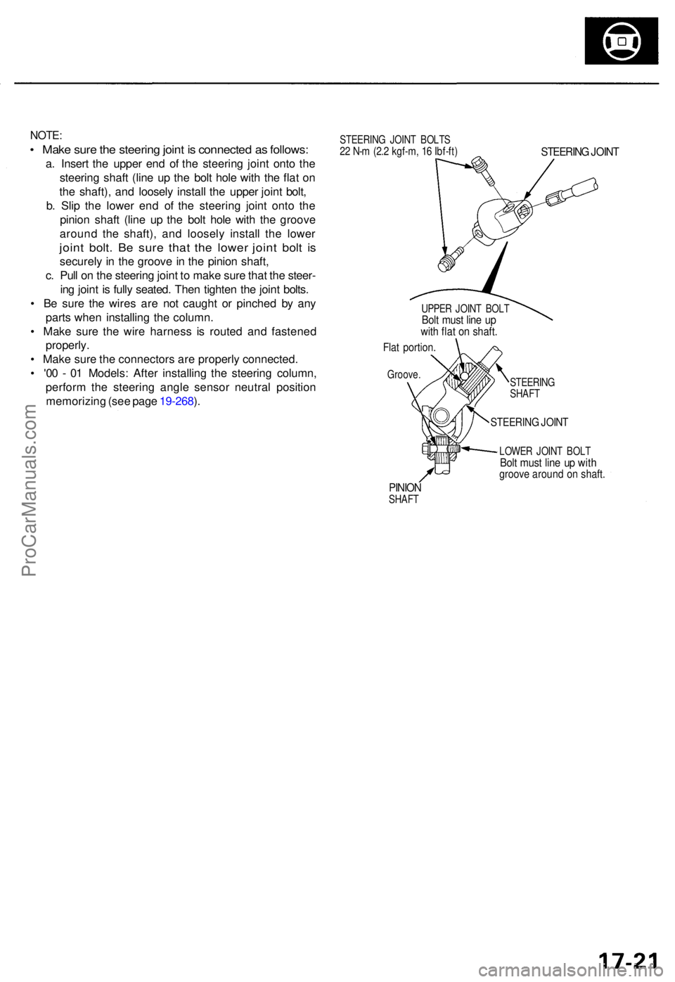
NOTE:
• Mak e sur e th e steerin g join t i s connecte d a s follows :
a. Inser t th e uppe r en d o f th e steerin g join t ont o th e
steerin g shaf t (lin e u p th e bol t hol e wit h th e fla t o n
th e shaft) , an d loosel y instal l th e uppe r join t bolt ,
b . Sli p th e lowe r en d o f th e steerin g join t ont o th e
pinio n shaf t (lin e u p th e bol t hol e wit h th e groov e
aroun d th e shaft) , an d loosel y instal l th e lowe r
joint bolt . B e sur e tha t th e lowe r join t bol t i s
securel y i n th e groov e in th e pinio n shaft ,
c . Pul l o n th e steerin g join t t o mak e sur e tha t th e steer -
in g join t i s full y seated . The n tighte n th e join t bolts .
• B e sur e th e wire s ar e no t caugh t o r pinche d b y an y
part s whe n installin g th e column .
• Mak e sur e th e wir e harnes s i s route d an d fastene d
properly .
• Mak e sur e th e connector s ar e properl y connected .
• '0 0 - 0 1 Models : Afte r installin g th e steerin g column ,
perfor m th e steerin g angl e senso r neutra l positio n
memorizin g (se e pag e 19-268 ).
STEERIN G JOIN T BOLT S22 N- m (2. 2 kgf-m , 1 6 Ibf-ft )STEERIN G JOIN T
UPPE R JOIN T BOL TBolt mus t lin e u pwit h fla t o n shaft .
Flat portion .
Groove.
STEERING
SHAF T
STEERIN G JOIN T
LOWE R JOIN T BOL TBolt mus t lin e u p wit hgroov e aroun d o n shaft .
PINIONSHAF T
ProCarManuals.com
Page 988 of 1954

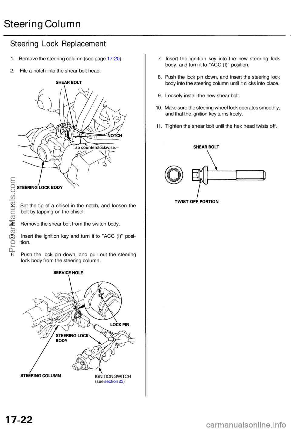
Steering Loc k Replacemen t
1. Remov e th e steerin g colum n (se e pag e 17-20 ).
2 . Fil e a notc h int o th e shea r bol t head .
Steerin g Colum n
7. Inser t th e ignitio n ke y int o th e ne w steerin g loc k
body , an d tur n it t o "AC C (I) " position .
8 . Pus h th e loc k pi n down , an d inser t th e steerin g loc k
bod y int o th e steerin g colum n unti l i t click s int o place .
9 . Loosel y instal l th e ne w shea r bolt .
10 . Mak e sur e th e steerin g whee l loc k operate s smoothly ,
an d tha t th e ignitio n ke y turn s freely .
11 . Tighte n th e shea r bol t unti l th e he x hea d twist s off .
3 . Se t th e ti p o f a chise l i n th e notch , an d loose n th e
bol t b y tappin g o n th e chisel .
4 . Remov e th e shea r bol t fro m th e switc h body .
5 . Inser t th e ignitio n ke y an d tur n i t t o "AC C (I) " posi -
tion.
6. Pus h th e loc k pi n down , an d pul l ou t th e steerin g
loc k bod y fro m th e steerin g column .
IGNITION SWITC H(see sectio n 23 )
ProCarManuals.com
Page 989 of 1954

Power Steering Hoses, Lines
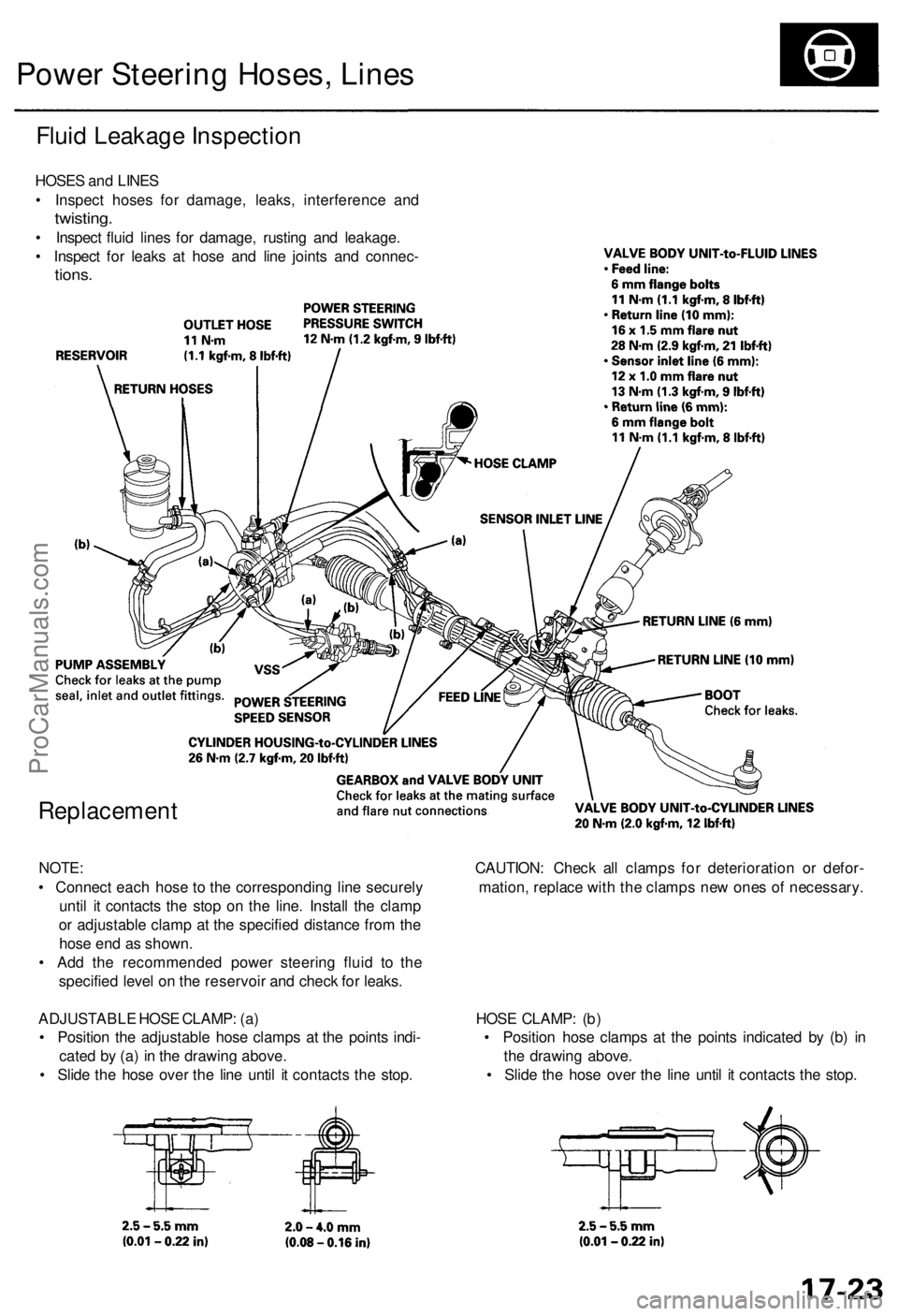
Fluid Leakage Inspection
HOSES and LINES
• Inspect hoses for damage, leaks, interference and
twisting.
• Inspect fluid lines for damage, rusting and leakage.
• Inspect for leaks at hose and line joints and connec-
tions.
Replacement
NOTE: CAUTION: Check all clamps for deterioration or defor-
• Connect each hose to the corresponding line securely mation, replace with the clamps new ones of necessary.
until it contacts the stop on the line. Install the clamp
or adjustable clamp at the specified distance from the
hose end as shown.
• Add the recommended power steering fluid to the
specified level on the reservoir and check for leaks.
ADJUSTABLE HOSE CLAMP: (a) HOSE CLAMP: (b)
• Position the adjustable hose clamps at the points indi- • Position hose clamps at the points indicated by (b) in
cated by (a) in the drawing above. the drawing above.
• Slide the hose over the line until it contacts the stop. • Slide the hose over the line until it contacts the stop.ProCarManuals.com