Page 1524 of 1954
*: Yo u ca n als o tes t th e switc h b y usin g th e self-diagnosi s functio n (mod e 2) . (Se e pag e 23-252 .)
Gaug e Assembl y
Componen t Locatio n Inde x
GAUG E ASSEMBL Y
Gauge/Termina l Location s Index , pag e 23-7 5
Replacement , pag e 23-8 5
Bul b Locations , pag e 23-7 6
Select/Rese t Switc h Test , pag e 23-8 4
FUEL GAUG E SENDIN G UNI TSee sectio n 1 1
PARKIN G BRAK E SWITC HSee sectio n 1 9
BRAK E FLUI D LEVE L SWITC HSee sectio n 1 9
ENGIN E COOLAN T TEMPERATUR E (ECT )
GAUG E SENDIN G UNI TSee sectio n 1 0
ENGIN E OI L PRESSUR E SWITCH *
Se e sectio n 8
VEHICL E SPEE D SENSO R (VSS) *
Troubleshooting , pag e 23-8 6
Replacement , pag e 23-8 5
OUTSID
E AI R TEMPERATUR E
SENSORSee sectio n 2 2
ProCarManuals.com
Page 1525 of 1954
Gauge/Terminal Locatio n Inde x
CONNECTO R "A " (C508 ) CONNECTO
R "B " (C509 )
A/ T GEA R POSITIO N
INDICATO R
Se e sectio n 1 4
COOLAN T TEMPERATUR E GAUGE :
See sectio n 1 0
SAFET Y INDICATO R
Se e pag e 23-8 8
FUE
L GAUGE :
See sectio n 1 1
TRI P METER/OUTSID E
AI R TEMPERATUR E INDICATOR :
Se e pag e 23-8 4
SPEEDOMETER
:
Indicates 6 0 mp h a t 1,02 6 rp m(60 km/ h at 63 7 rpm ) of th evehicl e spee d sensor(VSS) .
TACHOMETER :Indicates 10 0 rp m a t30 0 pulse s pe r minut eof th e ignitio n controlmodul e (ICM) .
ProCarManuals.com
Page 1527 of 1954
Gauge Assembl y
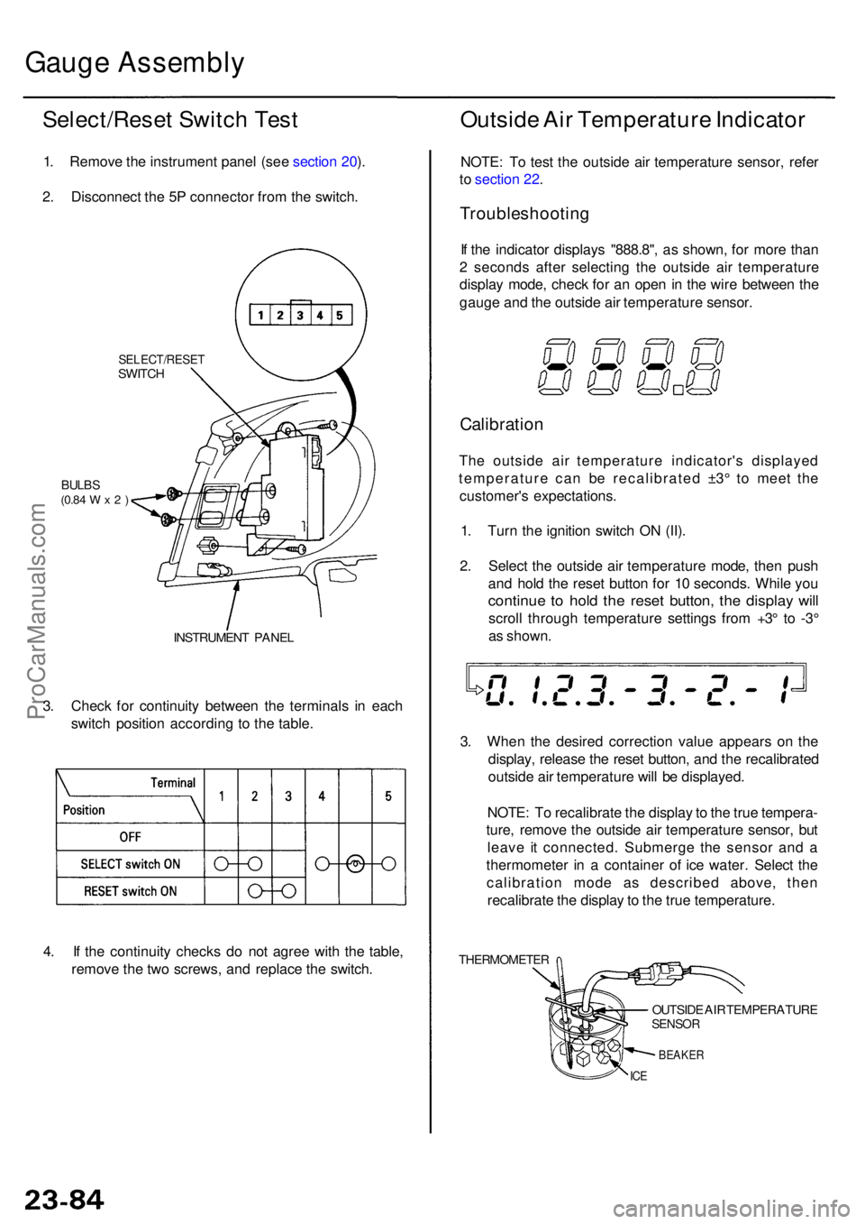
Select/Rese t Switc h Tes t
1. Remov e th e instrumen t pane l (se e sectio n 20 ).
2 . Disconnec t th e 5 P connecto r fro m th e switch .
SELECT/RESE TSWITCH
BULBS(0.84 W x 2 )
INSTRUMEN T PANE L
3. Chec k fo r continuit y betwee n th e terminal s i n eac h
switc h positio n accordin g t o th e table .
Outsid e Ai r Temperatur e Indicato r
NOTE: T o tes t th e outsid e ai r temperatur e sensor , refe r
t o sectio n 22 .
Troubleshootin g
If th e indicato r display s "888.8" , a s shown , fo r mor e tha n
2 second s afte r selectin g th e outsid e ai r temperatur e
displa y mode , chec k fo r a n ope n in th e wir e betwee n th e
gaug e an d th e outsid e ai r temperatur e sensor .
Calibratio n
The outsid e ai r temperatur e indicator' s displaye d
temperatur e ca n b e recalibrate d ±3 ° t o mee t th e
customer' s expectations .
1 . Tur n th e ignitio n switc h O N (II) .
2 . Selec t th e outsid e ai r temperatur e mode , the n pus h
an d hol d th e rese t butto n fo r 1 0 seconds . Whil e yo u
continu e t o hol d th e rese t button , th e displa y wil l
scrol l throug h temperatur e setting s fro m +3 ° t o -3 °
a s shown .
3 . Whe n th e desire d correctio n valu e appear s o n th e
display , releas e th e rese t button , an d th e recalibrate d
outsid e ai r temperatur e wil l b e displayed .
NOTE : T o recalibrat e th e displa y to th e tru e tempera -
ture , remov e th e outsid e ai r temperatur e sensor , bu t
leav e i t connected . Submerg e th e senso r an d a
thermomete r i n a containe r o f ic e water . Selec t th e
calibratio n mod e a s describe d above , the n
recalibrat e th e displa y to th e tru e temperature .
THERMOMETE R
OUTSIDE AI R TEMPERATUR ESENSOR
BEAKE R
ICE
4. I f th e continuit y check s d o no t agre e wit h th e table ,
remov e th e tw o screws , an d replac e th e switch .
ProCarManuals.com
Page 1529 of 1954
(To page 23-87) GR
N TES T HARNES S CLI P
TES
T HARNES S
07LA J-PT3020 A
Vehicle Spee d Senso r (VSS )
Troubleshootin g
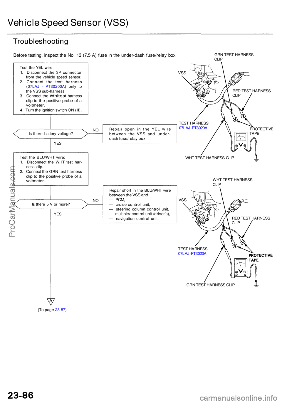
Before testing , inspec t th e No . 1 3 (7. 5 A ) fus e in th e under-das h fuse/rela y box .
Test th e YE L wire :
1 . Disconnec t th e 3 P connecto r
fro m th e vehicl e spee d sensor .
2 . Connec t th e tes t harnes s
( 07LA J - PT30200A ) onl y t o
th e VS S sub-harness .
3. Connec t the Whites t harnes sclip t o th e positiv e prob e o f avoltmeter .4. Tur n th e ignitio n switc h O N (II) .
Is ther e batter y voltage ? Repai
r ope n i n th e YE L wir e
betwee n th e VS S an d under -
das h fuse/rela y box .NO
YE S
Tes t th e BLU/WH T wire :
1 . Disconnec t th e WH T tes t har -
nes s clip .
2 . Connec t th e GR N tes t harnes s
clip t o th e positiv e prob e o f avoltmeter .
Is ther e 5 V or more ?NO
Repai r shor t i n th e BLU/WH T wir ebetwee n th e VS S an d— PCM ,— cruis e contro l unit ,
— steerin g colum n contro l unit ,
— multiple x contro l uni t (driver's) ,
— navigatio n contro l unit .
YES
GR N TES T HARNES SCLIP
VSS
TES T HARNES S
07LA J-PT3020 A RE
D TES T HARNES S
CLIP
PROTECTIV ETAPE
WHT TES T HARNES S CLI P
WH T TES T HARNES S
CLIP
VSS
RE D TES T HARNES SCLIP
ProCarManuals.com
Page 1534 of 1954
Safety Indicato r Syste m
Brake Ligh t Failur e Senso r Tes t
'96 - 9 8 models :
1 . Firs t mak e sur e th e brak e light s com e o n whe n th e
brak e peda l i s pressed .
• I f al l th e brak e light s com e on , g o t o ste p 2 .
• I f on e o f th e brak e light s doe s no t com e on , chec k
whethe r th e bul b is blown . I f th e bul b is OK , g o to
ste p 2 .
• I f non e o f th e brak e light s com e on , chec k th e
brak e ligh t circui t.
2 . Ope n th e trun k lid .
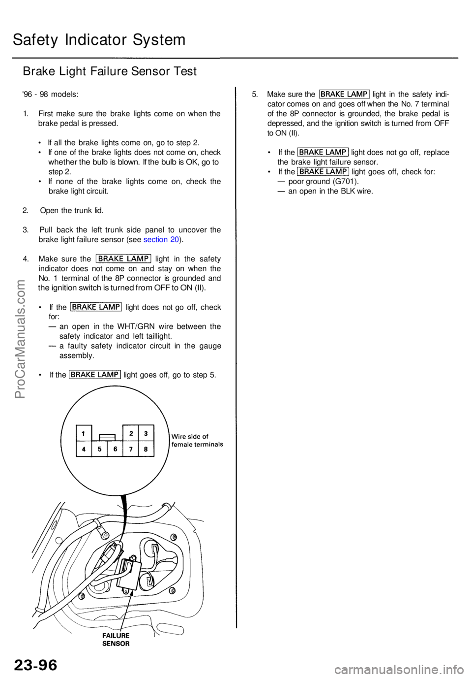
3 . Pul l bac k th e lef t trun k sid e pane l t o uncove r th e
brak e ligh t failur e senso r (se e sectio n 20 ).
4 . Mak e sur e th e ligh t i n th e safet y
indicato r doe s no t com e o n an d sta y o n whe n th e
No . 1 termina l o f th e 8 P connecto r i s grounde d an d
the ignitio n switc h is turne d fro m OF F to O N (II) .
• I f th e ligh t doe s no t g o off , chec k
for:
an ope n i n th e WHT/GR N wir e betwee n th e
safet y indicato r an d lef t taillight .
a fault y safet y indicato r circui t i n th e gaug e
assembly .
• I f th e ligh t goe s off , g o t o ste p 5 .
5. Mak e sur e th e ligh t i n th e safet y indi -
cato r come s o n an d goe s of f whe n th e No . 7 termina l
o f th e 8 P connecto r i s grounded , th e brak e peda l i s
depressed , an d th e ignitio n switc h is turne d fro m OF F
to O N (II) .
• I f th e ligh t doe s no t g o off , replac e
th e brak e ligh t failur e sensor .
• I f th e ligh t goe s off , chec k for :
poo r groun d (G701) .
an ope n i n th e BL K wire .
ProCarManuals.com
Page 1535 of 1954
'99 - 0 1 models :
1 . Firs t mak e sur e th e brak e light s com e o n whe n th e
brak e peda l i s pressed .
• I f al l th e brak e light s com e on , g o t o ste p 2 .
• I f on e o f th e brak e light s doe s no t com e on , chec k
whethe r th e bul b is blown . I f th e bul b is OK , g o to
ste p 2 .
• I f non e o f th e brak e light s com e on , chec k th e
brak e ligh t circui t.
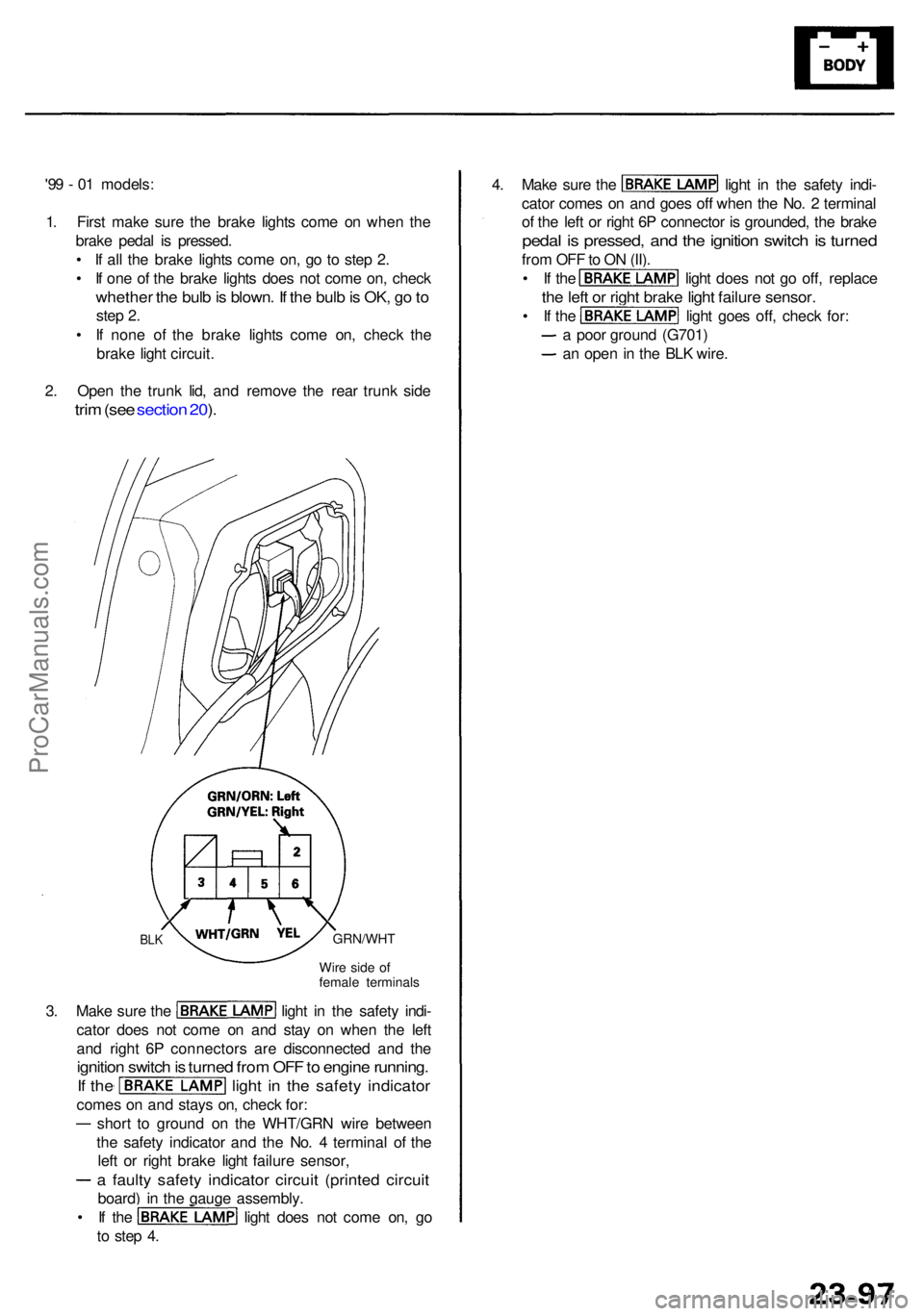
2 . Ope n th e trunk lid, an d remov e th e rea r trunk side
trim (se e sectio n 20 ).
4 . Mak e sur e th e ligh t i n th e safet y indi -
cato r come s o n an d goe s of f whe n th e No . 2 termina l
o f th e lef t o r righ t 6 P connecto r i s grounded , th e brak e
pedal i s pressed , an d th e ignitio n switc h is turne d
from OF F to O N (II) .
• I f th e ligh t doe s no t g o off , replac e
the lef t o r righ t brak e ligh t failur e sensor .
• I f th e ligh t goe s off , chec k for :
a poo r groun d (G701 )
an ope n in th e BL K wire .
Wire sid e o f
femal e terminal s
GRN/WH TBLK
3. Mak e sur e th e ligh t i n th e safet y indi -
cato r doe s no t com e o n an d sta y o n whe n th e lef t
an d righ t 6 P connector s ar e disconnecte d an d th e
ignitio n switc h is turne d fro m OF F to engin e running .
If th e ligh t i n th e safet y indicato r
comes o n an d stay s on , chec k for :
shor t t o groun d o n th e WHT/GR N wir e betwee n
th e safet y indicato r an d th e No . 4 termina l o f th e
lef t o r righ t brak e ligh t failur e sensor ,
a fault y safet y indicato r circui t (printe d circui t
board) i n th e gaug e assembly .
• I f th e ligh t doe s no t com e on , g o
t o ste p 4 .
ProCarManuals.com
Page 1536 of 1954
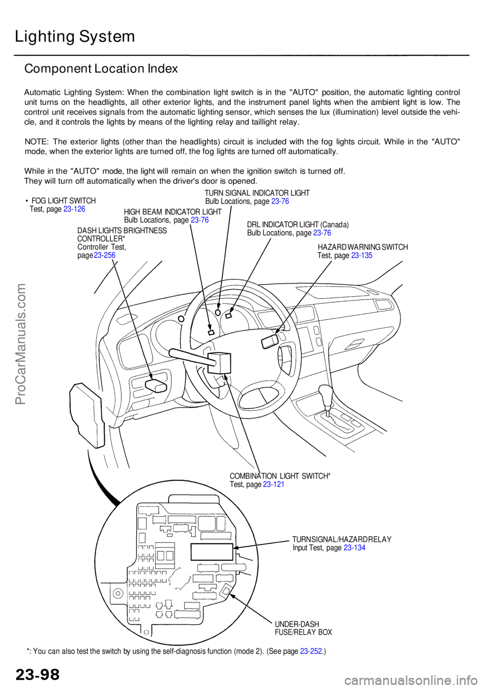
*: Yo u ca n als o tes t th e switc h b y usin g th e self-diagnosi s functio n (mod e 2) . (Se e pag e 23-252 .)
UNDER-DAS HFUSE/RELAY BO X
TUR N SIGNAL/HAZAR D RELA Y
Inpu t Test , pag e 23-13 4
COMBINATIO
N LIGH T SWITCH *
Test , pag e 23-12 1
DAS
H LIGHT S BRIGHTNES S
CONTROLLER *Controller Test ,
pag e 23-25 6
Lightin g Syste m
Componen t Locatio n Inde x
Automati c Lightin g System : Whe n th e combinatio n ligh t switc h i s i n th e "AUTO " position , th e automati c lightin g contro l
uni t turn s o n th e headlights , al l othe r exterio r lights , an d th e instrumen t pane l light s whe n th e ambien t ligh t i s low . Th e
contro l uni t receive s signal s fro m th e automati c lightin g sensor , whic h sense s th e lu x (illumination ) leve l outsid e th e vehi -
cle , an d it control s th e light s b y mean s o f th e lightin g rela y an d tailligh t relay .
NOTE : Th e exterio r light s (othe r tha n th e headlights ) circui t i s include d wit h th e fo g light s circuit . Whil e i n th e "AUTO "
mode , whe n th e exterio r light s ar e turne d off , th e fo g light s ar e turne d of f automatically .
Whil e in th e "AUTO " mode , th e ligh t wil l remai n o n whe n th e ignitio n switc h i s turne d off .
The y wil l tur n of f automaticall y whe n th e driver' s doo r i s opened .
• FO G LIGH T SWITC H
Test , pag e 23-12 6
HIGH BEA M INDICATO R LIGH T
Bul b Locations , pag e 23-7 6
TUR
N SIGNA L INDICATO R LIGH T
Bul b Locations , pag e 23-7 6
DR L INDICATO R LIGH T (Canada )
Bul b Locations , pag e 23-7 6
HAZAR D WARNIN G SWITC H
Test , pag e 23-13 5
ProCarManuals.com
Page 1537 of 1954
'96 - 9 8 models :
• HEADLIGH T
Replacement , pag e 23-12 1
Adjustment , pag e 23-12 4
• TAILLIGH T
Replacement , pag e 23-12 5 AUTOMATI
C
LIGHTIN GSENSOR(USA)
DIMME R RELA Y
Test , pag e 23-6 9
UNDER-HOO D
FUSE/RELA Y BO X
TAILLIGH T RELA YTest, pag e 23-6 8
HIG H MOUN T BRAK E LIGH T
Replacement , pag e 23-13 1
HEADLIGH
T RELA Y
Test , pag e 23-6 7
SIDE MARKE RLIGHT
FRON T TUR N
SIGNA L LIGH T
HEADLIGH
T an d
FRON T PARKIN G LIGH T
• AUTOMATI C LIGHTIN G
CONTRO L UNI T (USA )
Inpu t Test , pag e 23-11 4
• DAYTIM E RUNNIN G LIGHT S
CONTRO L UNI T (Canada )
Inpu t Test , pag e 23-11 6
FO
G LIGH T
Adjustment , pag e
23-12 7
SIDE MARKE RLIGHT
REAR TUR N
SIGNA L LIGH T BACK-U
P LIGH T
TAILLIGHT / Replacement
, pag e 23-12 5
BRAK E LIGH TReplacement , pag e 23-12 5LICENS
E PLAT E LIGHT S
Replacement , pag e 23-12 8
ProCarManuals.com