Page 1371 of 1954
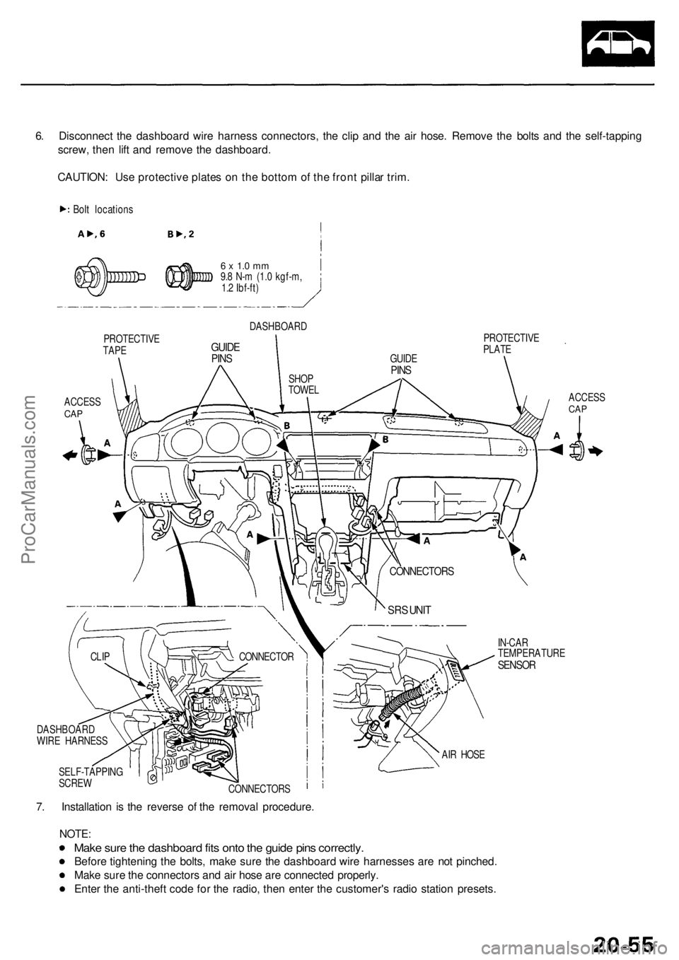
6. Disconnec t th e dashboar d wir e harnes s connectors , th e cli p an d th e ai r hose . Remov e th e bolt s an d th e self-tappin g
screw , the n lif t an d remov e th e dashboard .
CAUTION : Us e protectiv e plate s o n th e botto m of th e fron t pilla r trim .
Bolt location s
PROTECTIV E
TAPE
ACCES SCAP
6 x 1. 0 m m9.8 N- m (1. 0 kgf-m ,
1. 2 Ibf-ft )
DASHBOAR D
GUIDEPINS
PROTECTIV E
PLAT E
ACCESS
CAP
IN-CA R
TEMPERATUR E
SENSOR
7. Installatio n i s th e revers e o f th e remova l procedure .
NOTE:
Make sur e th e dashboar d fit s ont o th e guid e pin s correctly .
Before tightenin g th e bolts , mak e sur e th e dashboar d wir e harnesse s ar e no t pinched .
Mak e sur e th e connector s an d ai r hos e ar e connecte d properly .
Ente r th e anti-thef t cod e fo r th e radio , the n ente r th e customer' s radi o statio n presets .
SELF-TAPPIN G
SCRE W
CONNECTORS AI
R HOS E
CONNECTO
R
CLIP
DASHBOAR D
WIR E HARNES S
SRS UNI T
CONNECTOR S
GUIDEPINSSHO P
TOWE L
ProCarManuals.com
Page 1377 of 1954
Front Sea t
SEAT-BAC K
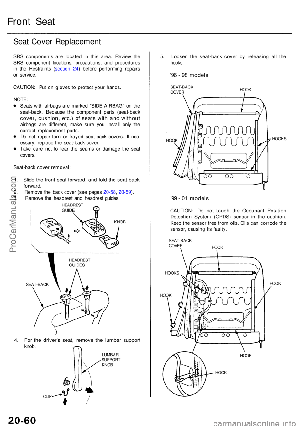
4. Fo r th e driver' s seat , remov e th e lumba r suppor t
knob.
CLIP
5. Loose n th e seat-bac k cove r b y releasin g al l th e
hooks .
'96 - 9 8 model s
SEAT-BAC K
COVE R HOO
K
HOO K HOOK
S
'99 - 0 1 model s
CAUTION : D o no t touc h th e Occupan t Positio n
Detectio n Syste m (OPDS ) senso r i n th e cushion .
Kee p th e senso r fre e fro m oils . Oil s ca n corrod e th e
sensor , causin g it s faulty .
SEAT-BAC KCOVER
HOOK S HOO
K
HOO K HOO
K
HOO K HOO
K
LUMBA
R
SUPPOR T
KNO B
HEADRES
T
GUIDES
Seat Cove r Replacemen t
SRS component s ar e locate d i n thi s area . Revie w th e
SR S componen t locations , precautions , an d procedure s
i n th e Restraint s ( sectio n 24 ) befor e performin g repair s
o r service .
CAUTION : Pu t o n glove s t o protec t you r hands .
NOTE:
Seats wit h airbag s ar e marke d "SID E AIRBAG " o n th e
seat-back . Becaus e th e componen t part s (seat-bac k
cover, cushion , etc. ) o f seat s wit h an d withou t
airbags ar e different , mak e sur e yo u instal l onl y th e
correc t replacemen t parts .
D o no t repai r tor n o r fraye d seat-back covers. I f nec -
essary , replac e th e seat-bac k cover .
Tak e car e no t t o tea r th e seam s o r damag e th e sea t
covers .
Seat-bac k cove r removal :
1. Slid e th e fron t sea t forward , an d fol d th e seat-bac k
forward.
2 . Remov e th e bac k cove r (se e page s 20-58 , 20-59 ).
3 . Remov e th e headres t an d headres t guides .
KNOB
HEADRES TGUIDE
ProCarManuals.com
Page 1382 of 1954
Page 1423 of 1954
Wiring/Connector Location s
SRS component s ar e locate d i n thi s area . Revie w th e SR S componen t locations , precautions , an d procedure s i n th e SR S
( sectio n 24 ) befor e performin g repair s o r service .
BLOWE R MOTO R
CONNECTO R
EVAPORATO RTEMPERATUR ESENSORTest, pag e 22-6 3 RECIRCULATIO
N CONTRO L
MOTO R CONNECTO R
SUNLIGH T SENSO R
CONNECTO R BLOWE
R MOTO R RELA Y
Wir e colors : BLK/YEL ,
WHT , RED/BL K an d BL K
Test , pag e 22-6 4
BLOWE R MOTO R HIG H RELA Y
Wir e colors : BLK/YEL ,
BLU/RED , L T GR N an d BL K
Test , pag e 22-6 4
POWE R TRANSISTO R
Test , pag e 22-6 3
AI R MI X CONTRO L MOTO R
Replacement , pag e 22-5 7
Test , pag e 22-5 7
MOD E CONTRO L
MOTOR CONNECTO R
IN-CAR TEMPERATUR E
SENSO R CONNECTO R
CLIMATE CONTRO L
UNIT CONNECTOR S
ProCarManuals.com
Page 1425 of 1954
Description
Fan Contro l Uni t
The fa n contro l uni t make s calculation s base d o n signal s fro m th e radiato r fa n contro l sensor . I t the n control s th e opera -
tio n o f th e radiato r fan , condense r fa n an d A/ C system .
ON
OF F
172° F (78°C )
183°F (84°C )Whe
n engin e coolan t temperatur e is abov e 183° F (84°C) ,
th e fa n contro l uni t turn s Tr 1 ON , an d th e radiato r fa n
(Low ) an d condense r fa n run s (Low) .
ON
OF F
183° F (84°C )
When engin e coolan t temperatur e is abov e 194° F (90°C) ,
th e fa n contro l uni t turn s Tr 2 ON , an d th e radiato r fa n
(High ) runs , an d th e condense r fa n (High ) goe s on .
194° F (90°C )
ON
OF F
225° F (107°C )When engin e coolan t temperatur e is abov e 228° F (109°C) ,
the fa n contro l uni t turn s Tr 3 OFF , an d stop s th e A/ C com -
pressor .
228°F (109°C )
*1: CONDENSE R FA N RELA Y*2: RADIATO R FA N RELA Y*3: RADIATO R FA N MAI N RELA Y
RED/WH T
ProCarManuals.com
Page 1429 of 1954
Troubleshooting
Self-diagnosis Functio n
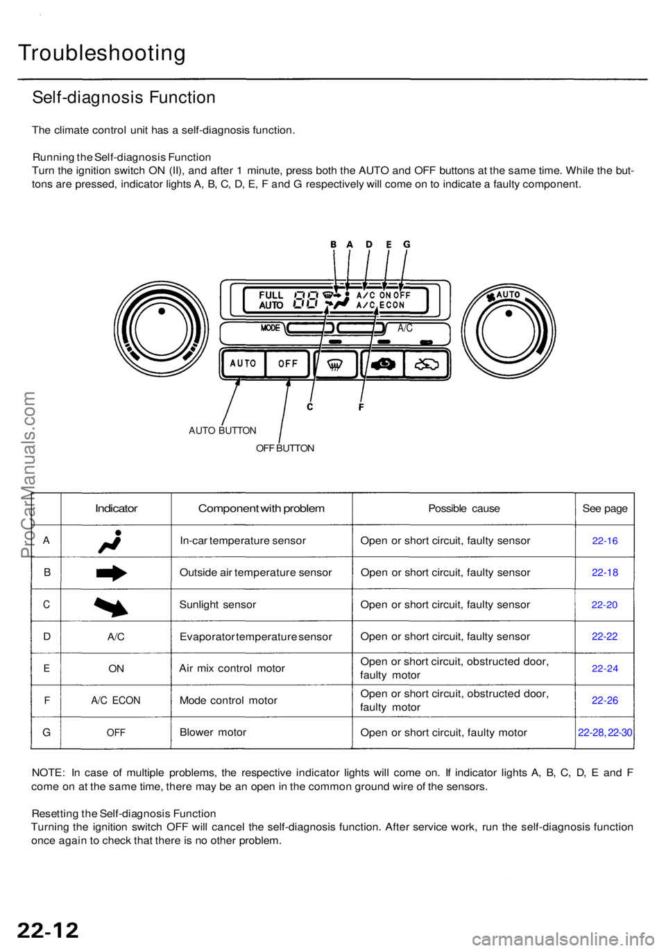
The climat e contro l uni t ha s a self-diagnosi s function .
Runnin g th e Self-diagnosi s Functio n
Tur n th e ignitio n switc h O N (II) , an d afte r 1 minute , pres s bot h th e AUT O an d OF F button s a t th e sam e time . Whil e th e but -
ton s ar e pressed , indicato r light s A , B , C , D , E , F an d G respectivel y wil l com e o n to indicat e a fault y component .
A/C
AUT O BUTTO N
OFF BUTTO N
A
B
C
D
E
F
G
Indicator
A/C
ON
A/ C ECO N
OFF
Componen t wit h proble m
In-car temperatur e senso r
Outsid e ai r temperatur e senso r
Sunligh t senso r
Evaporato r temperatur e senso r
Ai r mi x contro l moto r
Mod e contro l moto r
Blowe r moto r Possibl
e caus e
Ope n o r shor t circuit , fault y senso r
Ope n o r shor t circuit , fault y senso r
Ope n o r shor t circuit , fault y senso r
Ope n o r shor t circuit , fault y senso r
Ope n o r shor t circuit , obstructe d door ,
fault y moto r
Ope n o r shor t circuit , obstructe d door ,
fault y moto r
Ope n o r shor t circuit , fault y moto r Se
e pag e22-1 6
22-1 8
22-20
22-2 2
22-2 4
22-26
22-28 , 22-3 0
NOTE : I n cas e o f multipl e problems , th e respectiv e indicato r light s wil l com e on . I f indicato r light s A , B , C , D , E an d F
com e o n a t th e sam e time , ther e ma y b e a n ope n in th e commo n groun d wir e o f th e sensors .
Resettin g th e Self-diagnosi s Functio n
Turnin g th e ignitio n switc h OF F wil l cance l th e self-diagnosi s function . Afte r servic e work , ru n th e self-diagnosi s functio n
onc e agai n t o chec k tha t ther e is n o othe r problem .
ProCarManuals.com
Page 1430 of 1954
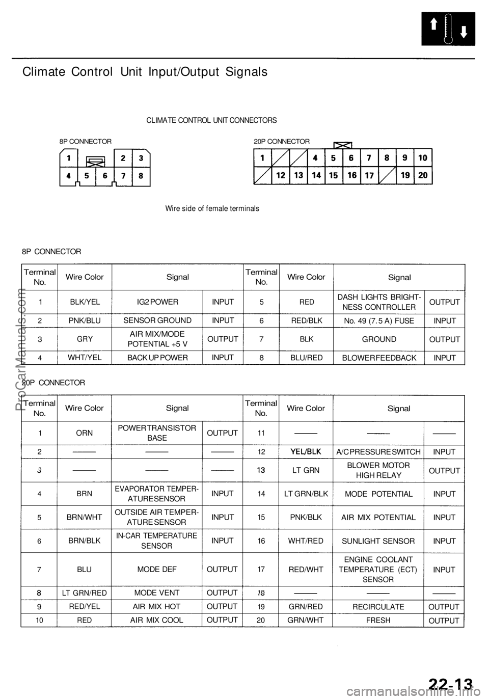
Climate Contro l Uni t Input/Outpu t Signal s
8P CONNECTO R
CLIMATE CONTRO L UNI T CONNECTOR S
20P CONNECTO R
Wire sid e o f femal e terminal s
8P CONNECTO R
Terminal
No.
1
2
3
4
Wir e Colo r
BLK/YE L
PNK/BL U
GRY
WHT/YE L
Signal
IG2 POWE R
SENSO R GROUN D
AIR MIX/MOD E
POTENTIA L + 5 V
BAC K U P POWE R INPU
T
INPU T
OUTPU T
INPU T
Termina l
No.
5
6
7
8
Wir e Colo r
RED
RED/BL K
BLK
BLU/RE D
Signal
DASH LIGHT S BRIGHT -
NESS CONTROLLER
No . 4 9 (7 . 5 A ) FUS E
GROUN D
BLOWE R FEEDBAC KOUTPU
T
INPU T
OUTPU T
INPU T
20 P CONNECTO R
Terminal
No.
1
2
3
4
5
6
7
9
10
Wir e Colo r
ORN
BRN
BRN/WH T
BRN/BLK
BLU
LT GRN/RE D
RED/YEL
RED
Signa l
POWE R TRANSISTO R
BASE
EVAPORATO R TEMPER -
ATURE SENSO R
OUTSID E AI R TEMPER -
ATUR E SENSO R
IN-CAR TEMPERATUR E
SENSOR
MODE DE F
MOD E VEN T
AIR MI X HO T
AIR MI X COO L OUTPU
T
INPU T
INPUT
INPU T
OUTPU T
OUTPU T
OUTPU T
OUTPU T
Terminal
No.
11
1 2
1 4
15
16
17
18
1 9
2 0
Wir e Colo r
LT GR N
LT GRN/BL K
PNK/BL K
WHT/RE D
RED/WH T
GRN/RED
GRN/WH T
Signal
A/C PRESSUR E SWITC H
BLOWE R MOTO R
HIG H RELA Y
MOD E POTENTIA L
AI R MI X POTENTIA L
SUNLIGH T SENSO R
ENGIN E COOLAN T
TEMPERATUR E (ECT )
SENSO R
RECIRCULAT E
FRESH
INPUT
OUTPU T
INPU T
INPU T
INPUT
INPU T
OUTPU T
OUTPU T
ProCarManuals.com
Page 1431 of 1954
Troubleshooting
In-car Temperatur e Senso r
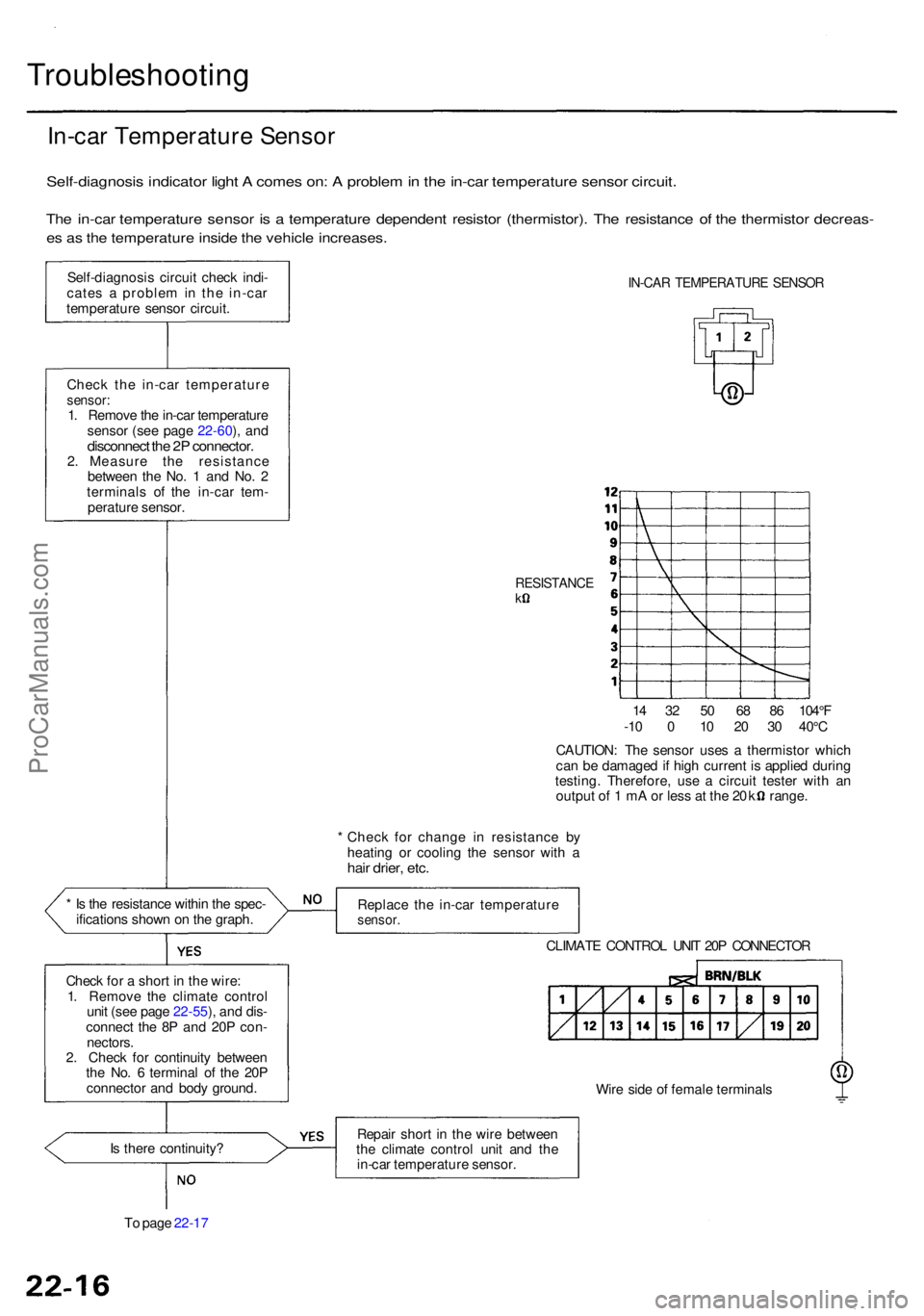
Self-diagnosi s indicato r ligh t A come s on : A proble m in th e in-ca r temperatur e senso r circuit .
The in-ca r temperatur e senso r i s a temperatur e dependen t resisto r (thermistor) . Th e resistanc e o f th e thermisto r decreas -
es a s th e temperatur e insid e th e vehicl e increases .
Self-diagnosi s circui t chec k indi -
cate s a proble m in th e in-ca r
temperatur e senso r circuit .
Chec k th e in-ca r temperatur e
sensor:1. Remov e th e in-ca r temperatur e
senso r (se e pag e 22-60 ), an d
disconnec t th e 2 P connector .2. Measur e th e resistanc e
betwee n th e No . 1 an d No . 2
terminal s o f th e in-ca r tem -
peratur e sensor .
* I s th e resistanc e withi n th e spec -
ification s show n o n th e graph .
Chec k fo r a shor t i n th e wire :
1 . Remov e th e climat e contro l
uni t (se e pag e 22-55 ), an d dis -
connec t th e 8 P an d 20 P con -
nectors .
2 . Chec k fo r continuit y betwee n
th e No . 6 termina l o f th e 20 P
connecto r an d bod y ground .
IN-CAR TEMPERATUR E SENSO R
RESISTANC Ek
14 3 2 5 0 6 8 8 6 104° F
-1 0 0 10 2 0 3 0 40° C
CAUTION : Th e senso r use s a thermisto r whic h
ca n b e damage d if hig h curren t i s applie d durin g
testing . Therefore , us e a circui t teste r wit h a n
outpu t o f 1 m A o r les s a t th e 2 0 k range .
* Chec k fo r chang e i n resistanc e b y
heatin g o r coolin g th e senso r wit h a
hai r drier , etc .
Replac e th e in-ca r temperatur esensor.
CLIMAT E CONTRO L UNI T 20 P CONNECTO R
Wir e sid e o f femal e terminal s
I s ther e continuity ?
T o pag e 22-1 7 Repai
r shor t i n th e wir e betwee n
th e climat e contro l uni t an d th e
in-ca r temperatur e sensor .
ProCarManuals.com