1996 ACURA RL KA9 sensor
[x] Cancel search: sensorPage 1454 of 1954
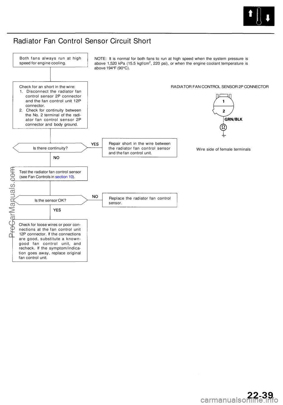
Radiator Fa n Contro l Senso r Circui t Shor t
NOTE : I t i s norma l fo r bot h fan s t o ru n a t hig h spee d whe n th e syste m pressur e i s
abov e 1,52 0 kP a (15. 5 kgf/cm2, 22 0 psi) , o r whe n th e engin e coolan t temperatur e i s
abov e 194° F (90°C) .
RADIATOR FA N CONTRO L SENSO R 2P CONNECTO R
I s ther e continuity ? Repai
r shor t i n th e wir e betwee n
th e radiato r fa n contro l senso r
an d th e fa n contro l unit . Wir
e sid e o f femal e terminal s
Tes t th e radiato r fa n contro l senso r
(se e Fa n Control s in sectio n 10 ).
I s th e senso r OK ? Replac
e th e radiato r fa n contro l
sensor.
Check fo r loos e wire s o r poo r con -
nection s a t th e fa n contro l uni t
12 P connector . I f th e connection s
ar e good , substitut e a known -
goo d fa n contro l unit , an d
recheck . I f th e symptom/indica -
tio n goe s away , replac e origina l
fa n contro l unit .
Chec
k fo r a n shor t i n th e wire :
1 . Disconnec t th e radiato r fa n
contro l senso r 2 P connecto r
and th e fa n contro l uni t 12 Pconnector .
2 . Chec k fo r continuit y betwee n
th e No . 2 termina l o f th e radi -
ato r fa n contro l senso r 2 P
connecto r an d bod y ground .
Bot
h fan s alway s ru n a t hig h
spee d fo r engin e cooling .
ProCarManuals.com
Page 1466 of 1954
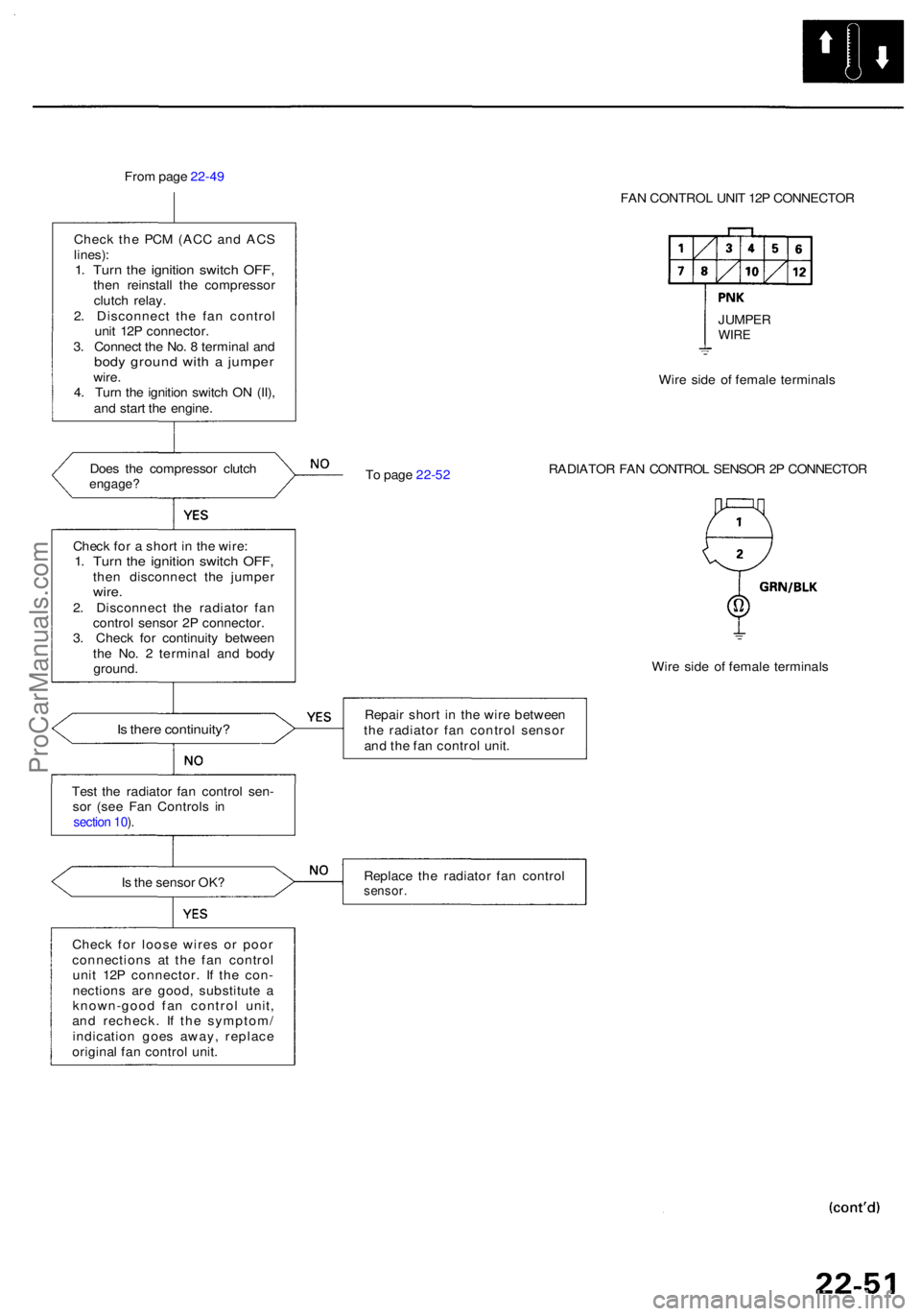
From pag e 22-4 9
Chec k th e PC M (AC C an d AC S
lines) :1. Tur n th e ignitio n switc h OFF ,then reinstal l th e compresso r
clutc h relay .
2 . Disconnec t th e fa n contro l
uni t 12 P connector .
3 . Connec t th e No . 8 termina l an d
bod y groun d wit h a jumpe rwire.
4 . Tur n th e ignitio n switc h O N (II) ,
an d star t th e engine .
Doe s th e compresso r clutc h
engage ?
Is ther e continuity ?
Test th e radiato r fa n contro l sen -
so r (se e Fa n Control s i n
section 10 ).
Is th e senso r OK ?
Chec k fo r loos e wire s o r poo r
connection s a t th e fa n contro l
uni t 12 P connector . I f th e con -
nection s ar e good , substitut e a
known-goo d fa n contro l unit ,
an d recheck . I f th e symptom /
indicatio n goe s away , replac e
origina l fa n contro l unit . FA
N CONTRO L UNI T 12 P CONNECTO R
T o pag e 22-5 2 Wir
e sid e o f femal e terminal s
RADIATO R FA N CONTRO L SENSO R 2 P CONNECTO R
Wir e sid e o f femal e terminal s
Repai r shor t i n th e wir e betwee n
th e radiato r fa n contro l senso r
an d th e fa n contro l unit .
Replac e th e radiato r fa n contro lsensor.
Check fo r a shor t i n th e wire :1. Tur n th e ignitio n switc h OFF ,then disconnec t th e jumpe rwire.2. Disconnec t th e radiato r fa n
contro l senso r 2 P connector .
3 . Chec k fo r continuit y betwee n
th e No . 2 termina l an d bod y
ground . JUMPE
R
WIRE
ProCarManuals.com
Page 1476 of 1954
Outside Ai r Temperatur e Senso r
Replacemen t
Disconnect th e connecto r fro m th e outsid e tempera -
tur e sensor , the n remov e th e bol t an d th e outsid e
ai r temperatur e sensor .
6 x 1. 0 m m9.8 N- m (1. 0 kgf-m , 7. 2 Ibf-ft )
OUTSID E AI R TEMPERATUR E SENSO R
2. Instal l i n th e revers e orde r o f removal .
Test
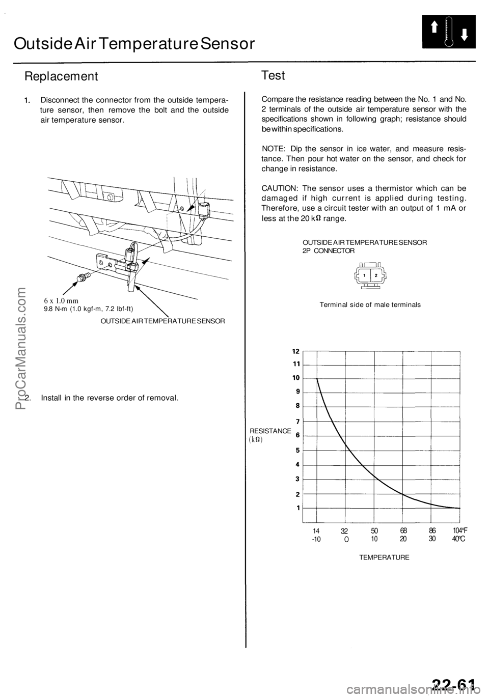
Compar e th e resistanc e readin g betwee n th e No . 1 an d No .
2 terminal s o f th e outsid e ai r temperatur e senso r wit h th e
specification s show n i n followin g graph ; resistanc e shoul d
be withi n specifications .
NOTE: Di p th e senso r i n ic e water , an d measur e resis -
tance . The n pou r ho t wate r o n th e sensor , an d chec k fo r
chang e in resistance .
CAUTION : Th e senso r use s a thermisto r whic h ca n b e
damage d i f hig h curren t i s applie d durin g testing .
Therefore , us e a circui t teste r wit h a n outpu t o f 1 m A o r
les s a t th e 2 0 k range .
OUTSIDE AI R TEMPERATUR E SENSO R
2 P CONNECTO R
Termina l sid e o f mal e terminal s
RESISTANC E(k )
14-1 032O501 0682 0863 0104° F40°C
TEMPERATUR E
ProCarManuals.com
Page 1477 of 1954
Sunlight Senso r
Replacemen t
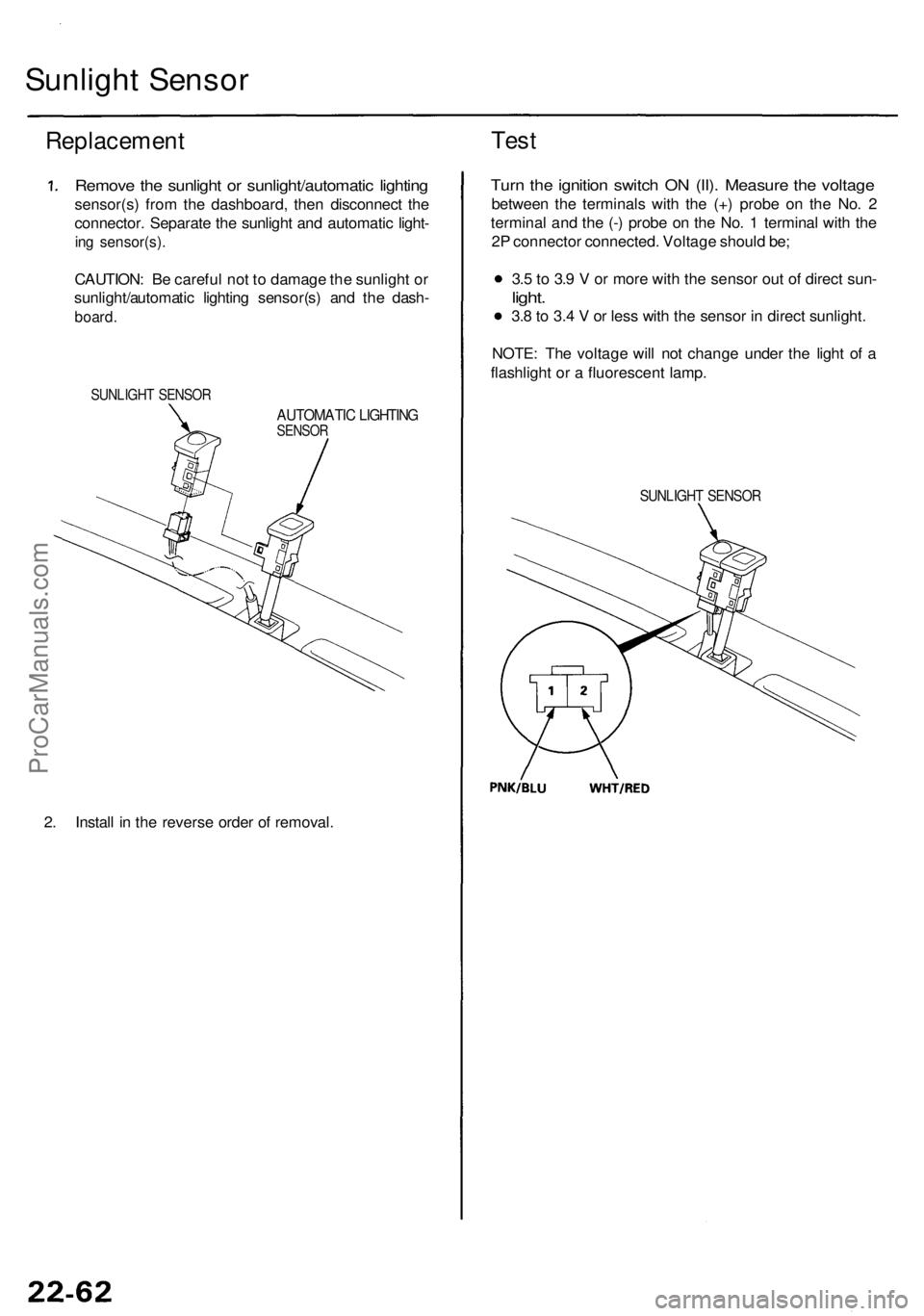
Remove th e sunligh t o r sunlight/automati c lightin g
sensor(s ) fro m th e dashboard , the n disconnec t th e
connector . Separat e th e sunligh t an d automati c light -
ing sensor(s) .
CAUTION: B e carefu l no t t o damag e th e sunligh t o r
sunlight/automati c lightin g sensor(s ) an d th e dash -
board .
SUNLIGH T SENSO R
AUTOMATI C LIGHTIN GSENSOR
2. Instal l i n th e revers e orde r o f removal .
Test
Turn th e ignitio n switc h O N (II) . Measur e th e voltag e
betwee n th e terminal s wit h th e (+ ) prob e o n th e No . 2
termina l an d th e (- ) prob e o n th e No . 1 termina l wit h th e
2 P connecto r connected . Voltag e shoul d be ;
3. 5 to 3. 9 V or mor e wit h th e senso r ou t o f direc t sun -
light.
3.8 to 3. 4 V or les s wit h th e senso r i n direc t sunlight .
NOTE : Th e voltag e wil l no t chang e unde r th e ligh t o f a
flashligh t o r a fluorescen t lamp .
SUNLIGH T SENSO R
ProCarManuals.com
Page 1478 of 1954
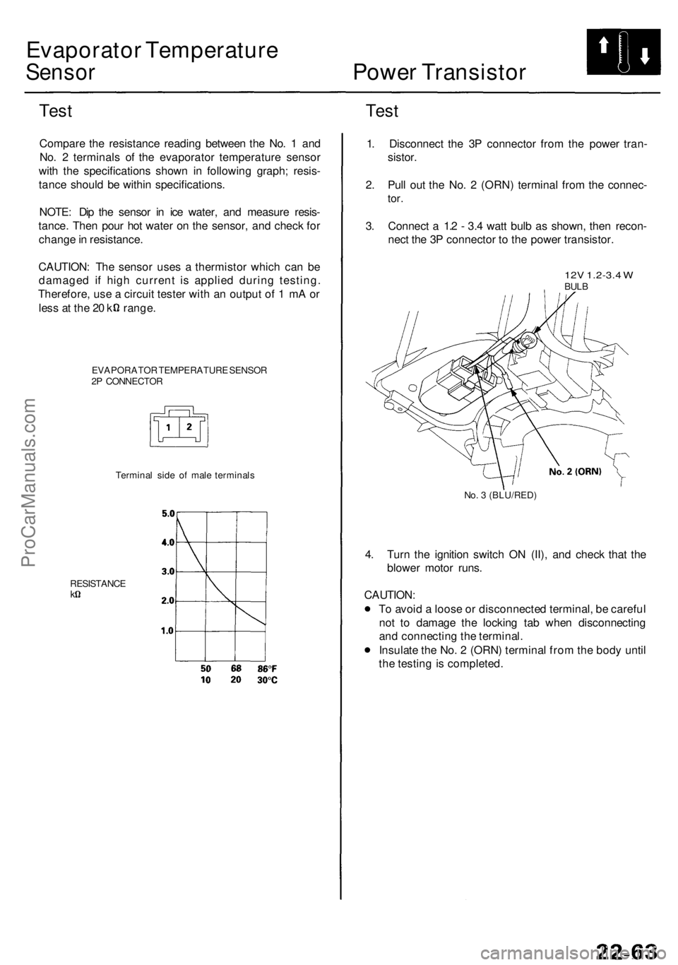
Evaporator Temperatur e
Sensor Powe r Transisto r
Test
Compar e th e resistanc e readin g betwee n th e No . 1 an d
No . 2 terminal s o f th e evaporato r temperatur e senso r
wit h th e specification s show n i n followin g graph ; resis -
tanc e shoul d b e withi n specifications .
NOTE : Di p th e senso r i n ic e water , an d measur e resis -
tance . The n pou r ho t wate r o n th e sensor , an d chec k fo r
chang e in resistance .
CAUTION : Th e senso r use s a thermisto r whic h ca n b e
damage d i f hig h curren t i s applie d durin g testing .
Therefore , us e a circui t teste r wit h a n outpu t o f 1 m A o r
les s a t th e 2 0 k range .
EVAPORATO R TEMPERATUR E SENSO R
2 P CONNECTO R
Test
Termina l sid e o f mal e terminal s
RESISTANC E
k
1. Disconnec t th e 3 P connecto r fro m th e powe r tran -
sistor .
2 . Pul l ou t th e No . 2 (ORN ) termina l fro m th e connec -
tor.
3. Connec t a 1. 2 - 3. 4 wat t bul b a s shown , the n recon -
nec t th e 3 P connecto r t o th e powe r transistor .
12V 1.2-3. 4 WBUL B
No. 3 (BLU/RED )
4. Tur n th e ignitio n switc h O N (II) , an d chec k tha t th e
blowe r moto r runs .
CAUTION :
T o avoi d a loos e o r disconnecte d terminal , b e carefu l
no t t o damag e th e lockin g ta b whe n disconnectin g
an d connectin g th e terminal .
Insulat e th e No . 2 (ORN ) termina l fro m th e bod y unti l
th e testin g is completed .
ProCarManuals.com
Page 1480 of 1954
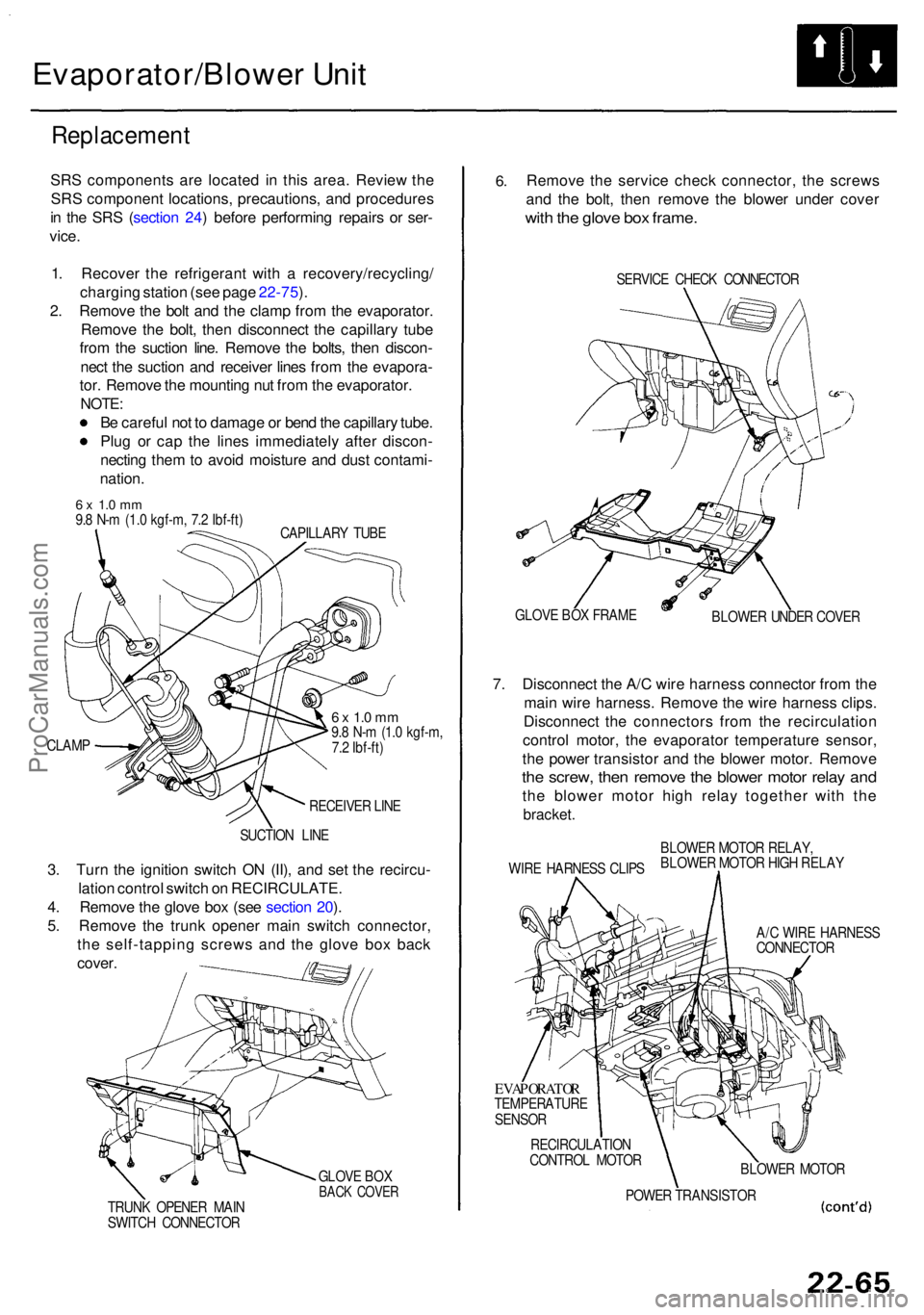
Evaporator/Blower Uni t
Replacemen t
SRS component s ar e locate d i n thi s area . Revie w th e
SR S componen t locations , precautions , an d procedure s
i n th e SR S (sectio n 24 ) befor e performin g repair s o r ser -
vice .
1 . Recove r th e refrigeran t wit h a recovery/recycling /
chargin g statio n (se e pag e 22-75 ).
2 . Remov e th e bol t an d th e clam p fro m th e evaporator .
Remov e th e bolt , the n disconnec t th e capillar y tub e
fro m th e suctio n line . Remov e th e bolts , the n discon -
nec t th e suctio n an d receive r line s fro m th e evapora -
tor . Remov e th e mountin g nu t fro m th e evaporator .
NOTE:
Be carefu l no t t o damag e o r ben d th e capillar y tube .
Plu g o r ca p th e line s immediatel y afte r discon -
nectin g the m to avoi d moistur e an d dus t contami -
nation .
6 x 1. 0 m m9.8 N- m (1. 0 kgf-m , 7. 2 Ibf-ft )
CAPILLAR Y TUB E
CLAM P
6 x 1. 0 m m9.8 N- m (1. 0 kgf-m ,
7. 2 Ibf-ft )
RECEIVE R LIN E
SUCTIO N LIN E
3. Tur n th e ignitio n switc h O N (II) , an d se t th e recircu -
latio n contro l switc h o n RECIRCULATE .
4 . Remov e th e glov e bo x (se e sectio n 20 ).
5 . Remov e th e trun k opene r mai n switc h connector ,
th e self-tappin g screw s an d th e glov e bo x bac k
cover .
GLOV E BO XBAC K COVE RTRUNK OPENE R MAI N
SWITC H CONNECTO R
6.Remov e th e servic e chec k connector , th e screw s
an d th e bolt , the n remov e th e blowe r unde r cove r
with th e glov e bo x frame .
SERVIC E CHEC K CONNECTO R
GLOV E BO X FRAM E
BLOWER UNDE R COVE R
7. Disconnec t th e A/ C wir e harnes s connecto r fro m th e
mai n wir e harness . Remov e th e wir e harnes s clips .
Disconnec t th e connector s fro m th e recirculatio n
contro l motor , th e evaporato r temperatur e sensor ,
th e powe r transisto r an d th e blowe r motor . Remov e
the screw , the n remov e th e blowe r moto r rela y an d
the blowe r moto r hig h rela y togethe r wit h th e
bracket .
WIRE HARNES S CLIP SBLOWE
R MOTO R RELAY ,
BLOWE R MOTO R HIG H RELA Y
A/ C WIR E HARNES S
CONNECTO R
EVAPORATO RTEMPERATUR E
SENSO R
RECIRCULATIO N
CONTRO L MOTO R
BLOWER MOTO R
POWE R TRANSISTO R
ProCarManuals.com
Page 1482 of 1954
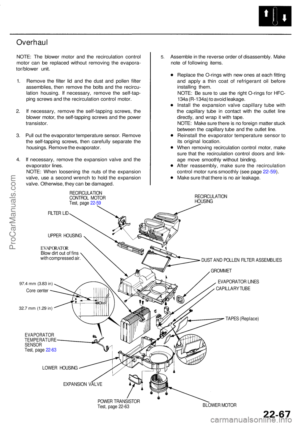
Overhaul
NOTE: Th e blowe r moto r an d th e recirculatio n contro l
moto r ca n b e replace d withou t removin g th e evapora -
tor/blowe r unit .
1 . Remov e th e filte r li d an d th e dus t an d polle n filte r
assemblies , the n remov e th e bolt s an d th e recircu -
latio n housing . I f necessary , remov e th e self-tap -
pin g screw s an d th e recirculatio n contro l motor .
2 . I f necessary , remov e th e self-tappin g screws , th e
blowe r motor , th e self-tappin g screw s an d th e powe r
transistor .
3 . Pul l ou t th e evaporato r temperatur e sensor . Remov e
th e self-tappin g screws , the n carefull y separat e th e
housings . Remov e th e evaporator .
4 . I f necessary , remov e th e expansio n valv e an d th e
evaporato r lines .
NOTE : Whe n loosenin g th e nut s o f th e expansio n
valve , us e a secon d wrenc h t o hol d th e expansio n
valve . Otherwise , the y ca n b e damaged .
RECIRCULATIO N
CONTRO L MOTO R
Test , pag e 22-5 9
FILTE R LI D
UPPE R HOUSIN G
EVAPORATO RBlow dir t ou t o f fin swith compresse d air .
97. 4 mm (3.8 3 in)
Cor e cente r
32.7 mm (1.2 9 in)
EVAPORATO R
TEMPERATUR E
SENSO R
Test, pag e 22-6 3
LOWE R HOUSIN G
EXPANSIO N VALV E
POWE R TRANSISTO R
Test , pag e 22-6 3
5.Assembl e in th e revers e orde r o f disassembly . Mak e
not e o f followin g items .
Replac e th e O-ring s wit h ne w one s a t eac h fittin g
an d appl y a thi n coa t of refrigeran t oi l befor e
installin g them .
NOTE : B e sur e to us e th e righ t O-ring s fo r HFC -
134 a (R-134a ) t o avoi d leakage .
Instal l th e expansio n valv e capillar y tub e wit h
th e capillar y tub e i n contac t wit h th e outle t lin e
directly , an d wra p it wit h tape .
NOTE : Mak e sur e ther e is n o foreig n matte r stuc k
betwee n th e capillar y tub e an d th e outle t line .
Reinstal l th e evaporato r temperatur e senso r t o
it s origina l location .
Whe n removin g recirculatio n contro l motor , mak e
sur e tha t th e recirculatio n contro l door s an d link -
ag e mov e smoothl y withou t binding .
Afte r reassembly , mak e sur e th e recirculatio n
contro l moto r run s smoothl y (se e pag e 22-59 ).
Mak e sur e tha t ther e is n o ai r leakage .
RECIRCULATIO N
HOUSIN G
DUS T AN D POLLE N FILTE R ASSEMBLIE S
GROMME T
EVAPORATO R LINE S
CAPILLAR Y TUB E
TAPE S (Replace )
BLOWE R MOTO R
ProCarManuals.com
Page 1493 of 1954
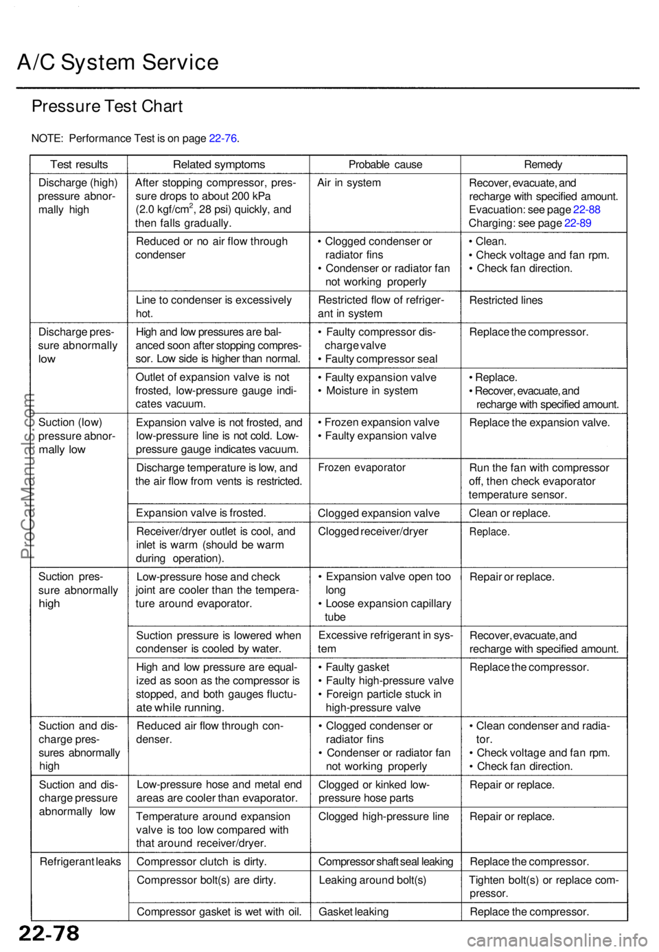
A/C Syste m Servic e
Pressur e Tes t Char t
NOTE : Performanc e Tes t i s o n pag e 22-76 .
Test result s
Discharg e (high )
pressur e abnor -
mall y hig h
Discharg e pres -
sur e abnormall y
low
Suctio n (low )
pressur e abnor -
mally lo w
Suctio n pres -
sur e abnormall y
high
Suctio n an d dis -
charg e pres -
sure s abnormall y
hig h
Suctio n an d dis -
charg e pressur e
abnormall y lo w
Refrigeran t leak s
Relate d symptom s
After stoppin g compressor , pres -
sur e drop s t o abou t 20 0 kP a
(2. 0 kgf/cm
2, 2 8 psi ) quickly , an d
the n fall s gradually .
Reduce d o r n o ai r flo w throug h
condense r
Lin e to condense r i s excessivel y
hot.
Hig h an d lo w pressure s ar e bal -
ance d soo n afte r stoppin g compres -
sor . Lo w sid e is highe r tha n normal .
Outle t o f expansio n valv e is no t
frosted , low-pressur e gaug e indi -
cate s vacuum .
Expansio n valv e is no t frosted , an d
low-pressur e lin e is no t cold . Low -
pressur e gaug e indicate s vacuum .
Discharg e temperatur e is low , an d
th e ai r flo w fro m vent s i s restricted .
Expansio n valv e is frosted .
Receiver/drye r outle t i s cool , an d
inle t i s war m (shoul d b e war m
durin g operation) .
Low-pressur e hos e an d chec k
join t ar e coole r tha n th e tempera -
tur e aroun d evaporator .
Suctio n pressur e is lowere d whe n
condense r i s coole d b y water .
Hig h an d lo w pressur e ar e equal -
ize d a s soo n a s th e compresso r i s
stopped , an d bot h gauge s fluctu -
ate whil e running .
Reduce d ai r flo w throug h con -
denser .
Low-pressur e hos e an d meta l en d
area s ar e coole r tha n evaporator .
Temperatur e aroun d expansio n
valv e i s to o lo w compare d wit h
tha t aroun d receiver/dryer .
Compresso r clutc h i s dirty .
Compresso r bolt(s ) ar e dirty .
Compresso r gaske t i s we t wit h oil . Probabl
e caus e
Ai r i n syste m
• Clogge d condense r o r
radiato r fin s
• Condense r o r radiato r fa n
no t workin g properl y
Restricte d flo w o f refriger -
an t i n syste m
• Fault y compresso r dis -
charg e valv e
• Fault y compresso r sea l
• Fault y expansio n valv e
• Moistur e in syste m
• Froze n expansio n valv e
• Fault y expansio n valv e
Froze n evaporato r
Clogged expansio n valv e
Clogge d receiver/drye r
• Expansio n valv e ope n to o
lon g
• Loos e expansio n capillar y
tub e
Excessiv e refrigeran t i n sys -
tem
• Fault y gaske t
• Fault y high-pressur e valv e
• Foreig n particl e stuc k in
high-pressur e valv e
• Clogge d condense r o r
radiato r fin s
• Condense r o r radiato r fa n
no t workin g properl y
Clogge d o r kinke d low -
pressur e hos e part s
Clogge d high-pressur e lin e
Compresso r shaf t sea l leakin g
Leakin g aroun d bolt(s )
Gaske t leakin g Remed
y
Recover , evacuate , an d
recharg e wit h specifie d amount .
Evacuation : se e pag e 22-8 8
Charging : se e pag e 22-8 9
• Clean .
• Chec k voltag e an d fa n rpm .
• Chec k fa n direction .
Restricte d line s
Replac e th e compressor .
• Replace .
• Recover , evacuate , an d
recharg e wit h specifie d amount .
Replac e th e expansio n valve .
Ru n th e fa n wit h compresso r
off , the n chec k evaporato r
temperatur e sensor .
Clea n o r replace .
Replace .
Repair o r replace .
Recover , evacuate , an d
recharg e wit h specifie d amount .
Replac e th e compressor .
• Clea n condense r an d radia -
tor.
• Chec k voltag e an d fa n rpm .
• Chec k fa n direction .
Repai r o r replace .
Repai r o r replace .
Replac e th e compressor .
Tighte n bolt(s ) o r replac e com -
pressor .
Replace th e compressor .
ProCarManuals.com