1996 ACURA RL KA9 sensor
[x] Cancel search: sensorPage 1615 of 1954
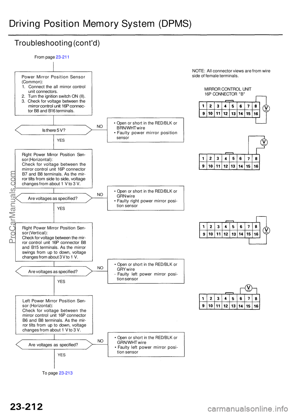
Driving Positio n Memor y Syste m (DPMS )
Troubleshootin g (cont'd )
From pag e 23-211
Powe r Mirro r Positio n Senso r
(Common) :1. Connec t th e al l mirro r contro l
uni t connectors .
2 . Tur n th e ignitio n switc h O N (II) .
3 . Chec k fo r voltag e betwee n th e
mirro r contro l uni t 16 P connec -tor B 8 an d B1 6 terminals .
Is ther e 5 V ?NO• Ope n o r shor t i n th e RED/BL K o rBRN/WH T wir e
• Fault y powe r mirro r positio n
sensorYES
Righ t Powe r Mirro r Positio n Sen -
so r (Horizontal) :
Chec k fo r voltag e betwee n th e
mirro r control unit 16 P connecto r
B 7 an d B 8 terminals . A s th e mir -
ror tilt s fro m sid e to side , voltag echange s fro m abou t 1 V to 3 V .
• Ope n o r shor t i n th e RED/BL K o rGR N wir e
• Fault y righ t powe r mirro r posi -
tion senso r
Are voltage s a s specified ?NO
YE S
Righ t Powe r Mirro r Positio n Sen -
so r (Vertical) :
Chec k fo r voltag e betwee n th e mir -
ro r contro l uni t 16 P connecto r B 8
an d B1 5 terminals . A s th e mirro r
swing s fro m u p t o down , voltag e
change s fro m abou t 3 V to 1 V .
Ar e voltage s a s specified ?
• Ope n o r shor t i n th e RED/BL K o rGR Y wir e
- Fault y lef t powe r mirro r posi -
tio n senso rNO
YE S
Lef t Powe r Mirro r Positio n Sen -sor (Horizontal) :Check fo r voltag e betwee n th e
mirro r contro l uni t 16 P connecto r
B 6 an d B 8 terminals . A s th e mir -
ro r tilt s fro m u p t o down , voltag e
change s fro m abou t 1 V to 3 V .
Ar e voltage s a s specified ?
NO• Ope n o r shor t i n th e RED/BL K o rGRN/WH T wir e
• Fault y lef t powe r mirro r posi -
tion senso rYES
To pag e 23-213 NOTE
: Al l connecto r view s ar e fro m wir e
sid e o f femal e terminals .
MIRROR CONTRO L UNI T16P CONNECTO R "B "
ProCarManuals.com
Page 1619 of 1954
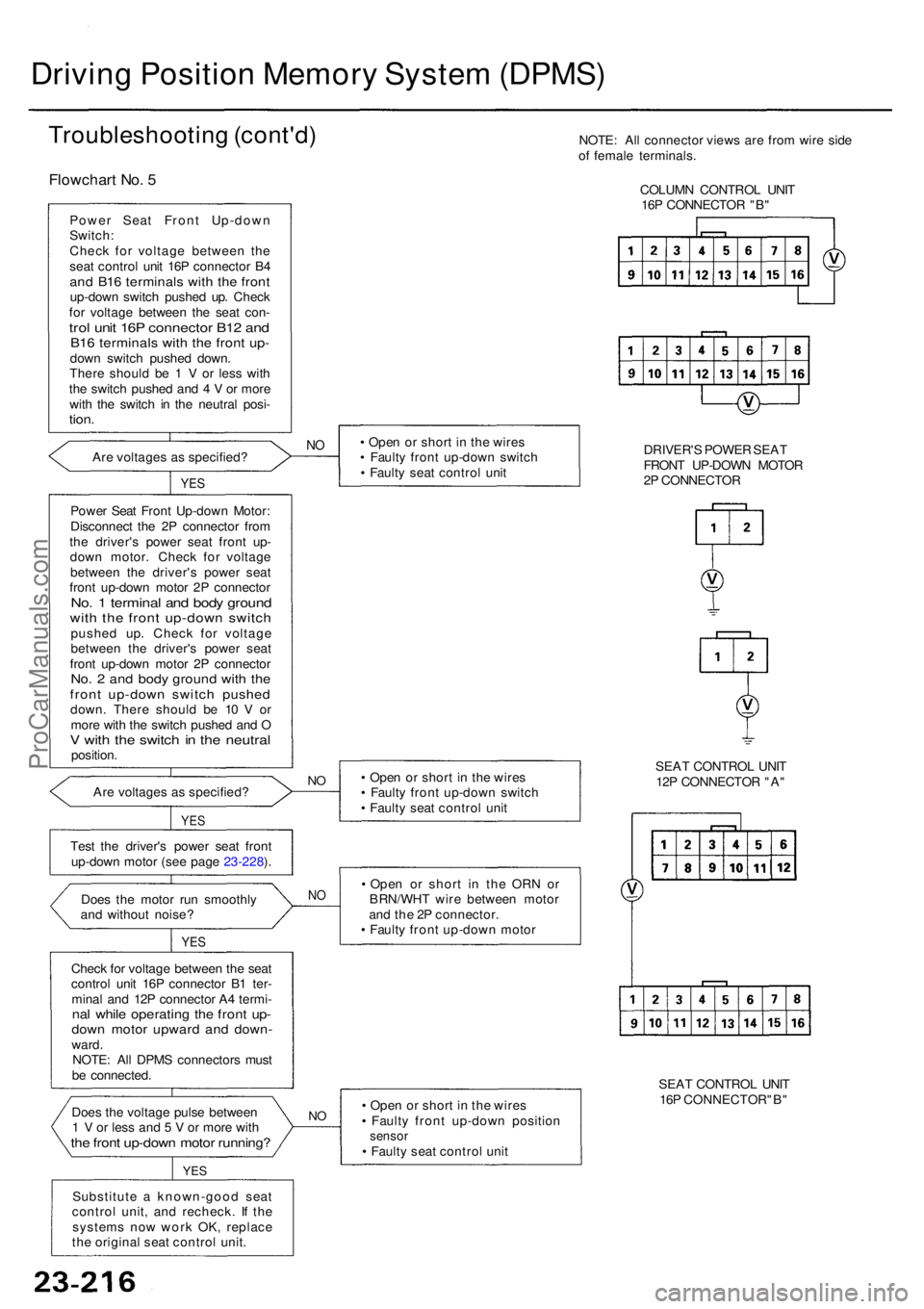
• Ope n o r shor t i n th e wire s
• Fault y fron t up-dow n positio n
sensor• Fault y sea t contro l uni t
Substitut e a known-goo d sea t
contro l unit , an d recheck . I f th e
system s no w wor k OK , replac e
th e origina l sea t contro l unit .
Doe
s th e voltag e puls e betwee n
1 V or les s an d 5 V or mor e wit hthe fron t up-dow n moto r running ?
YES
NO
Chec k fo r voltag e betwee n th e sea t
contro l uni t 16 P connecto r B 1 ter -
mina l an d 12 P connecto r A 4 termi -
nal whil e operatin g th e fron t up -dow n moto r upwar d an d down -ward.
NOTE : Al l DPM S connector s mus t
b e connected .
Doe
s th e moto r ru n smoothl y
an d withou t noise ?
YES
NO• Ope n o r shor t i n th e OR N o r
BRN/WH T wir e betwee n moto r
an d th e 2 P connector .
• Fault y fron t up-dow n moto r
Tes
t th e driver' s powe r sea t fron t
up-dow n moto r (se e pag e 23-228 ). •
Ope n o r shor t i n th e wire s
• Fault y fron t up-dow n switc h
• Fault y sea t contro l uni t
NOAr e voltage s a s specified ?
YES
Powe r Sea t Fron t Up-dow n Motor :
Disconnec t th e 2 P connecto r fro m
th e driver' s powe r sea t fron t up -
dow n motor . Chec k fo r voltag e
betwee n th e driver' s powe r sea t
fron t up-dow n moto r 2 P connecto r
No. 1 termina l an d bod y groun dwith th e fron t up-dow n switc hpushe d up . Chec k fo r voltag e
betwee n th e driver' s powe r sea t
fron t up-dow n moto r 2 P connecto r
No. 2 an d bod y groun d wit h th efron t up-dow n switc h pushe ddown. Ther e shoul d b e 1 0 V or
mor e wit h th e switc h pushe d an d O
V wit h th e switc h in th e neutra lposition . •
Ope n o r shor t i n th e wire s
• Fault y fron t up-dow n switc h
• Fault y sea t contro l uni t
NO
YE S
Are voltage s a s specified ?
Powe
r Sea t Fron t Up-dow n
Switch :
Chec k fo r voltag e betwee n th e
sea t contro l uni t 16 P connecto r B 4
an d B1 6 terminal s wit h th e fron tup-dow n switc h pushe d up . Chec k
fo r voltag e betwee n th e sea t con -
trol uni t 16 P connecto r B1 2 an dB16 terminal s wit h th e fron t up -dow n switc h pushe d down .
Ther e shoul d b e 1 V or les s wit h
th e switc h pushe d an d 4 V or mor e
wit h th e switc h i n th e neutra l posi -
tion.
Flowchar t No . 5
Troubleshootin g (cont'd )
Driving Positio n Memor y Syste m (DPMS )
NOTE: Al l connecto r view s ar e fro m wir e sid e
o f femal e terminals .
COLUM N CONTRO L UNI T
16 P CONNECTO R "B "
DRIVER' S POWE R SEA T
FRON T UP-DOW N MOTO R
2 P CONNECTO R
SEA T CONTRO L UNI T
12 P CONNECTO R "A "
SEA T CONTRO L UNI T
16 P CONNECTOR"B "
ProCarManuals.com
Page 1620 of 1954
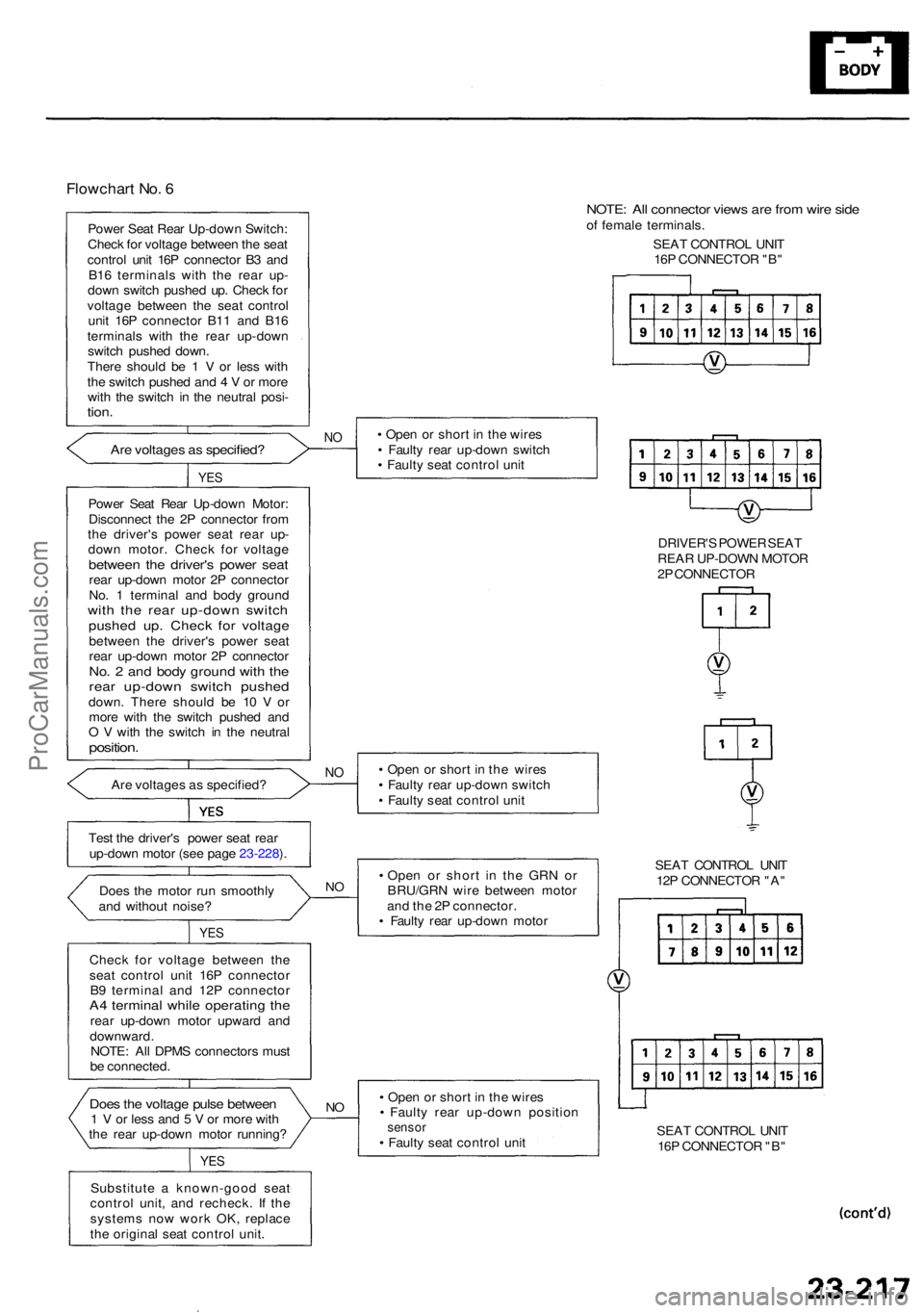
Flowchart No . 6
Powe r Sea t Rea r Up-dow n Switch :
Chec k fo r voltag e betwee n th e sea t
contro l uni t 16 P connecto r B 3 an d
B1 6 terminal s wit h th e rea r up -
dow n switc h pushe d up . Chec k fo r
voltag e betwee n th e sea t contro l
uni t 16 P connecto r B1 1 an d B1 6
terminal s wit h th e rea r up-dow n
switc h pushe d down .
Ther e shoul d b e 1 V or les s wit h
th e switc h pushe d an d 4 V or mor e
wit h th e switc h i n th e neutra l posi -
tion.
Are voltage s a s specified ?NO• Ope n o r shor t i n th e wire s
• Fault y rea r up-dow n switc h
• Fault y sea t contro l uni t
YES
Powe r Sea t Rea r Up-dow n Motor :
Disconnec t th e 2 P connecto r fro m
th e driver' s powe r sea t rea r up -
dow n motor . Chec k fo r voltag e
between th e driver' s powe r sea trear up-dow n moto r 2 P connecto r
No . 1 termina l an d bod y groun d
with th e rea r up-dow n switc hpushed up . Chec k fo r voltag ebetwee n th e driver' s powe r sea t
rea r up-dow n moto r 2 P connecto r
No. 2 an d bod y groun d wit h th erea r up-dow n switc h pushe ddown. Ther e shoul d b e 1 0 V or
mor e wit h th e switc h pushe d an d
O V wit h th e switc h i n th e neutra l
position.
Are voltage s a s specified ?NO• Ope n o r shor t i n th e wire s
• Fault y rea r up-dow n switc h
• Fault y sea t contro l uni t
Tes t th e driver' s powe r sea t rea r
up-dow n moto r (se e pag e 23-228 ).
Doe s th e moto r ru n smoothl y
an d withou t noise ? •
Ope n o r shor t i n th e GR N o r
BRU/GR N wir e betwee n moto r
an d th e 2 P connector .
• Fault y rea r up-dow n moto r
NO
YE S
Chec k fo r voltag e betwee n th e
sea t contro l uni t 16 P connecto r
B 9 termina l an d 12 P connecto r
A4 termina l whil e operatin g th erea r up-dow n moto r upwar d an d
downward .
NOTE : Al l DPM S connector s mus t
b e connected .
• Ope n o r shor t i n th e wire s
• Fault y rea r up-dow n positio n
sensor• Fault y sea t contro l uni t
NODoe s th e voltag e puls e betwee n1 V or les s an d 5 V or mor e wit h
th e rea r up-dow n moto r running ?
YES
Substitut e a known-goo d sea t
contro l unit , an d recheck . I f th e
system s no w wor k OK , replac e
th e origina l sea t contro l unit . SEA
T CONTRO L UNI T
16 P CONNECTO R "B "
SEA
T CONTRO L UNI T
12 P CONNECTO R "A "
NOTE : Al l connecto r view s ar e fro m wir e sid eof femal e terminals .
SEA T CONTRO L UNI T
16 P CONNECTO R "B "
DRIVER' S POWE R SEA T
REA R UP-DOW N MOTO R
2 P CONNECTO R
ProCarManuals.com
Page 1622 of 1954
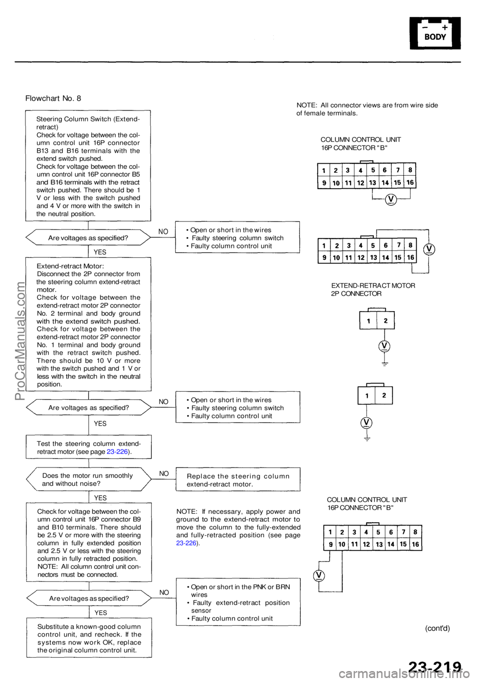
Flowchart No . 8
Steerin g Colum n Switc h (Extend -
retract )
Chec k fo r voltag e betwee n th e col -
um n contro l uni t 16 P connecto r
B1 3 an d B1 6 terminal s wit h th e
exten d switc h pushed .
Chec k fo r voltag e betwee n th e col -
um n contro l uni t 16 P connecto r B 5
an d B1 6 terminal s wit h th e retrac tswitch pushed . Ther e shoul d b e 1
V o r les s wit h th e switc h pushe d
an d 4 V or mor e wit h th e switc h in
th e neutra l position .
• Ope n o r shor t i n th e wire s
• Fault y steerin g colum n switc h
• Fault y colum n contro l uni t
NOAr e voltage s a s specified ?
YES
Extend-retrac t Motor :Disconnec t th e 2 P connecto r fro m
th e steerin g colum n extend-retrac t
motor.Chec k fo r voltag e betwee n th e
extend-retrac t moto r 2 P connecto r
No . 2 termina l an d bod y groun d
with th e exten d switc h pushed .Check fo r voltag e betwee n th e
extend-retrac t moto r 2 P connecto r
No . 1 termina l an d bod y groun d
wit h th e retrac t switc h pushed .
Ther e shoul d b e 1 0 V or mor e
wit h th e switc h pushe d an d 1 V or
les s wit h th e switc h in th e neutra lposition .
Ar e voltage s a s specified ?
NO• Ope n o r shor t i n th e wire s
• Fault y steerin g colum n switc h
• Fault y colum n contro l uni t
YES
Tes t th e steerin g colum n extend -
retrac t moto r (se e pag e 23-226 ).
Replace th e steerin g colum n
extend-retrac t motor .
Doe
s th e moto r ru n smoothl y
an d withou t noise ?
YES
NO
NOTE : I f necessary , appl y powe r an dgroun d t o th e extend-retrac t moto r t omov e th e colum n t o th e fully-extende d
an d fully-retracte d positio n (se e pag e
23-226 ).
Chec k fo r voltag e betwee n th e col -
um n contro l uni t 16 P connecto r B 9
an d B1 0 terminals . Ther e shoul d
b e 2. 5 V or mor e wit h th e steerin g
colum n i n full y extende d positio n
an d 2. 5 V or les s wit h th e steerin g
colum n in full y retracte d position .
NOTE : Al l colum n contro l uni t con -
nector s mus t b e connected .
Ar e voltage s a s specified ?
NO• Ope n o r shor t i n th e PN K o r BR Nwire s• Fault y extend-retrac t positio nsensor• Fault y colum n contro l uni t
Substitut e a known-goo d colum n
contro l unit , an d recheck . I f th e
system s no w wor k OK , replac e
th e origina l colum n contro l unit .YES
COLUM N CONTRO L UNI T
16 P CONNECTO R "B "
(cont'd )
NOTE: Al l connecto r view s ar e fro m wir e sid e
o f femal e terminals .
COLUM N CONTRO L UNI T
16 P CONNECTO R "B "
EXTEND-RETRAC T MOTO R2P CONNECTO R
ProCarManuals.com
Page 1625 of 1954
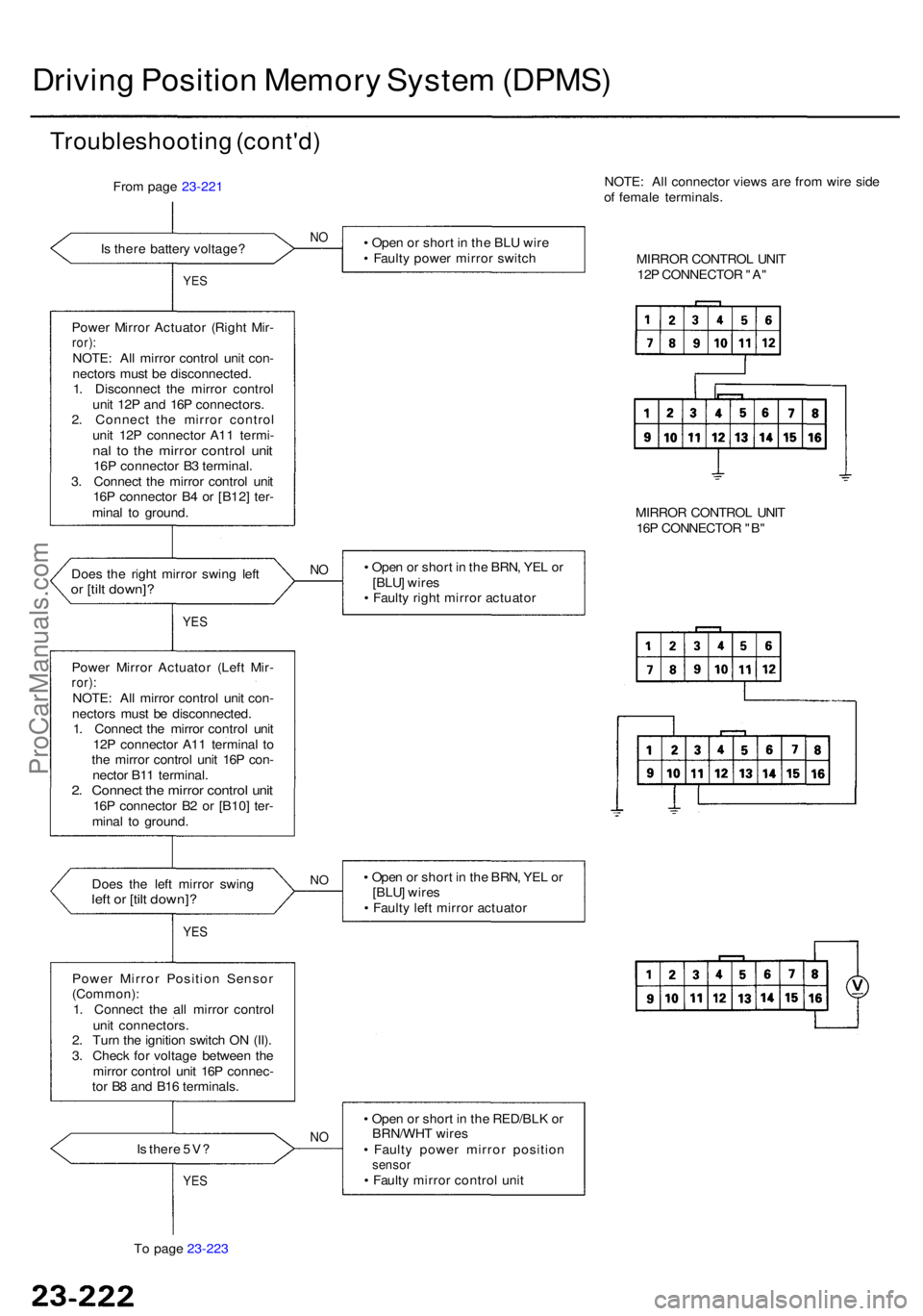
Driving Positio n Memor y Syste m (DPMS )
Troubleshootin g (cont'd )
From pag e 23-221
I s ther e batter y voltage ?
NO• Ope n o r shor t i n th e BL U wir e
• Fault y powe r mirro r switc h
YES
Powe r Mirro r Actuato r (Righ t Mir -ror) :NOTE : Al l mirro r contro l uni t con -
nector s mus t b e disconnected .
1 . Disconnec t th e mirro r contro l
uni t 12 P an d 16 P connectors .
2 . Connec t th e mirro r contro l
uni t 12 P connecto r A1 1 termi -
nal t o th e mirro r contro l uni t16P connecto r B 3 terminal .
3 . Connec t th e mirro r contro l uni t
16 P connecto r B 4 o r [B12 ] ter -
mina l t o ground . NOTE
: Al l connecto r view s ar e fro m wir e sid e
o f femal e terminals .
MIRRO R CONTRO L UNI T
12 P CONNECTO R "A "
MIRRO R CONTRO L UNI T
16 P CONNECTO R "B "
• Ope n o r shor t i n th e BRN , YE L o r
[BLU ] wire s
• Fault y righ t mirro r actuato r
Doe
s th e righ t mirro r swin g lef t
or [til t down]?
N O
YE S
Powe r Mirro r Actuato r (Lef t Mir -ror):NOTE : Al l mirro r contro l uni t con -
nector s mus t b e disconnected .
1 . Connec t th e mirro r contro l uni t
12 P connecto r A1 1 termina l t o
th e mirro r contro l uni t 16 P con -
necto r B1 1 terminal .
2. Connec t th e mirro r contro l uni t16P connecto r B 2 o r [B10 ] ter -
mina l t o ground .
Doe s th e lef t mirro r swin g
left o r [til t down] ?
• Ope n o r shor t i n th e BRN , YE L o r
[BLU ] wire s
• Fault y lef t mirro r actuato rNO
YE S
Powe r Mirro r Positio n Senso r(Common) :1. Connec t th e al l mirro r contro l
uni t connectors .
2 . Tur n th e ignitio n switc h O N (II) .
3 . Chec k fo r voltag e betwee n th e
mirro r contro l uni t 16 P connec -
to r B 8 an d B1 6 terminals .
• Ope n o r shor t i n th e RED/BL K o r
BRN/WH T wire s
• Fault y powe r mirro r positio n
sensor• Fault y mirro r contro l uni t
NOIs ther e 5V ?
YES
To pag e 23-223
ProCarManuals.com
Page 1629 of 1954
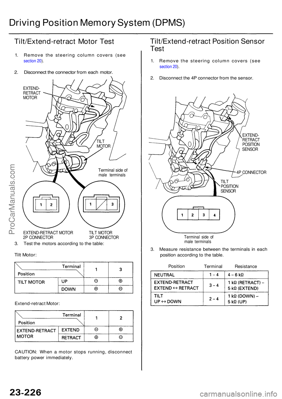
Driving Positio n Memor y Syste m (DPMS )
Tilt/Extend-retrac t Moto r Tes t
1. Remove the steering column covers (see
section 20 ).
2 . Disconnec t th e connecto r fro m eac h motor .
EXTEND -RETRAC TMOTOR
EXTEND-RETRAC T MOTO R TIL T MOTO R
2 P CONNECTO R 3 P CONNECTO R
3. Tes t th e motor s accordin g t o th e table :
Tilt Motor :
Extend-retrac t Motor :
CAUTION : Whe n a moto r stop s running , disconnec t
batter y powe r immediately .
Tilt/Extend-retrac t Positio n Senso r
Test
1. Remove the steering column covers (see
section 20 ).
2 . Disconnec t th e 4 P connecto r fro m th e sensor .
EXTEND -RETRAC TPOSITION
SENSO R
4 P CONNECTO R
Termina l sid e o f
mal e terminal s
3. Measur e resistanc e betwee n th e terminal s i n eac h
positio n accordin g t o th e table .
Positio nTermina lResistanc e
Terminal sid e o fmal e terminal s
TIL
T
MOTO R
TILT
POSITIO N
SENSO R
ProCarManuals.com
Page 1632 of 1954
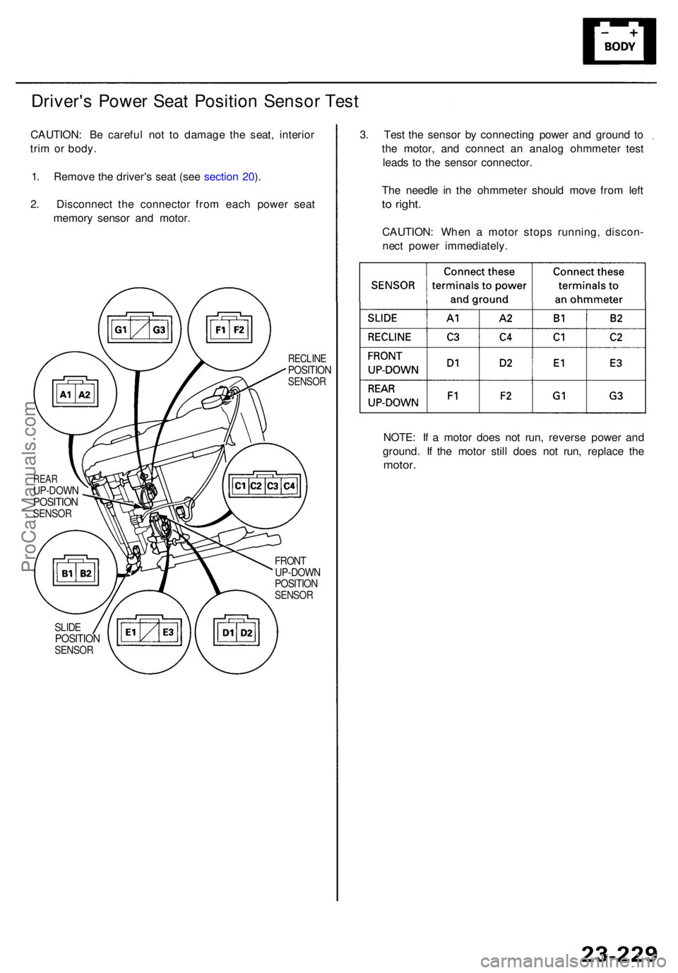
Driver's Powe r Sea t Positio n Senso r Tes t
CAUTION : B e carefu l no t t o damag e th e seat , interio r
tri m o r body .
1 . Remov e th e driver' s sea t (se e sectio n 20 ).
2 . Disconnec t th e connecto r fro m eac h powe r sea t
memor y senso r an d motor .
RECLIN EPOSITIO NSENSOR
REARUP-DOW NPOSITIONSENSOR
FRONT
UP-DOW N
POSITIO N
SENSOR
SLIDEPOSITIO NSENSOR
NOTE: I f a moto r doe s no t run , revers e powe r an d
ground . I f th e moto r stil l doe s no t run , replac e th e
motor .
3. Tes t th e senso r b y connectin g powe r an d groun d t o
th e motor , an d connec t a n analo g ohmmete r tes t
lead s t o th e senso r connector .
Th e needl e i n th e ohmmete r shoul d mov e fro m lef t
to right .
CAUTION : Whe n a moto r stop s running , discon -
nec t powe r immediately .
ProCarManuals.com
Page 1636 of 1954
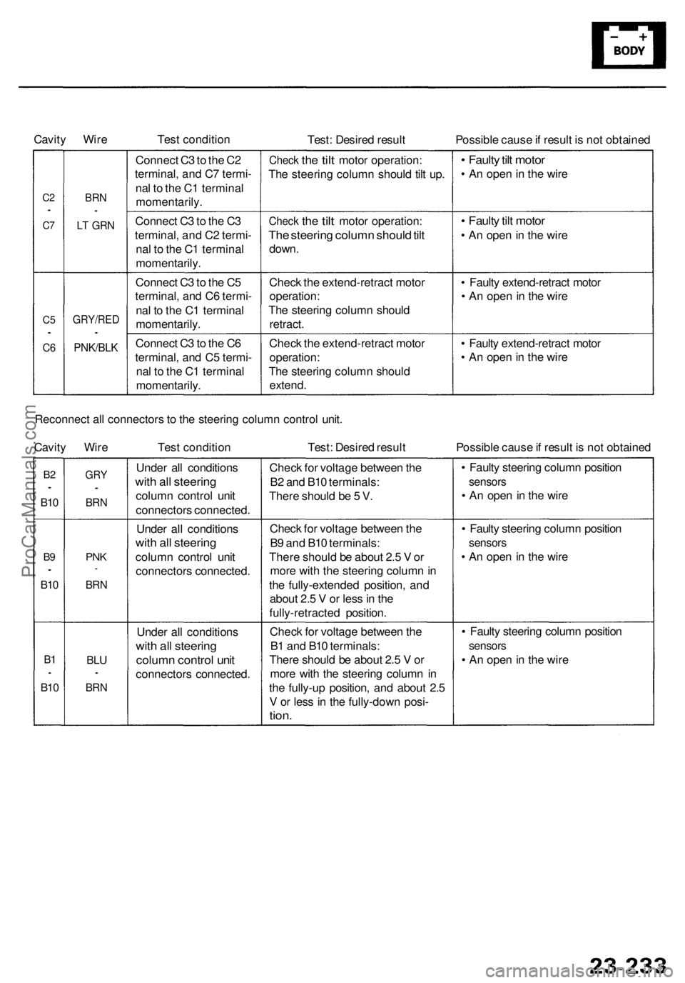
Cavity Wire
Test condition
Test: Desired result
Possible cause if result is not obtained
C2
•
C7
C5
•
C6
BRN
•
LT GRN
GRY/RED
•
PNK/BLK
Connect C3 to the C2
terminal, and C7 termi-
nal to the C1 terminal
momentarily.
Connect C3 to the C3
terminal, and C2 termi-
nal to the C1 terminal
momentarily.
Connect C3 to the C5
terminal, and C6 termi-
nal to the C1 terminal
momentarily.
Connect C3 to the C6
terminal, and C5 termi-
nal to the C1 terminal
momentarily.
Check
the
tilt
motor operation:
The steering column should tilt up.
Check
the
tilt
motor operation:
The steering column should tilt
down.
Check the extend-retract motor
operation:
The steering column should
retract.
Check the extend-retract motor
operation:
The steering column should
extend.
• Faulty tilt motor
• An open in the wire
• Faulty tilt motor
• An open in the wire
• Faulty extend-retract motor
• An open in the wire
• Faulty extend-retract motor
• An open in the wire
Reconnect all connectors to the steering column control unit.
Cavity Wire
Test condition
Test: Desired result
Possible cause if result is not obtained
B2
•
B10
B9
•
B10
B1
•
B10
GRY
•
BRN
PNK
*
BRN
BLU
•
BRN
Under all conditions
with all steering
column control unit
connectors connected.
Under all conditions
with all steering
column control unit
connectors connected.
Under all conditions
with all steering
column control unit
connectors connected.
Check for voltage between the
B2 and B10 terminals:
There should be 5 V.
Check for voltage between the
B9 and B10 terminals:
There should be about 2.5 V or
more with the steering column in
the fully-extended position, and
about 2.5 V or less in the
fully-retracted position.
Check for voltage between the
B1 and B10 terminals:
There should be about 2.5 V or
more with the steering column in
the fully-up position, and about 2.5
V or less in the fully-down posi-
tion.
• Faulty steering column position
sensors
• An open in the wire
• Faulty steering column position
sensors
• An open in the wire
• Faulty steering column position
sensors
• An open in the wireProCarManuals.com