1996 ACURA RL KA9 sensor
[x] Cancel search: sensorPage 1793 of 1954
SRS Airba g Syste m - '9 9 - 0 1 Model s
SRS Airba g
The SR S is a safet y devic e which , whe n use d i n conjunctio n wit h th e sea t belt , i s designe d t o hel p protec t th e drive r an d
fron t passenge r i n a fronta l impac t exceedin g a certai n se t limit . Th e syste m consist s o f th e SR S uni t (including safing sen -
so r an d fron t impac t sensor) , th e cabl e reel , th e driver' s airba g an d fron t passenger' s airbag .
Sid e Airbag s
Sid e airbag s locate d i n eac h fron t seat-bac k ca n hel p protec t th e uppe r tors o o f th e drive r o r fron t sea t passenge r during a
moderat e t o sever e sid e impact . Sensor s i n eac h doo r sil l an d i n th e SR S uni t detec t suc h a n impac t an d instantl y inflat e
th e driver' s o r th e passenger' s sid e airbag . Onl y on e sid e airba g wil l deplo y durin g a sid e impact . I f th e impac t i s o n th e
passenger' s side , th e passenger' s sid e airba g wil l deplo y eve n if ther e is n o passenger .
Th e sid e airba g syste m als o include s a n Occupan t Positio n Detectio n Syste m (OPDS) . Thi s syste m consist s o f sensor s an d
a contro l uni t locate d i n th e fron t passenger' s seat-back . Th e contro l uni t send s occupan t heigh t an d positio n dat a t o th e
SR S unit . I f th e SR S uni t determine s tha t th e fron t passenger' s hea d i s i n th e deploymen t pat h o f th e sid e airbag , i t wil l
automaticall y disabl e th e airbag . Whe n th e sid e airba g i s disabled , th e Sid e Airba g indicato r ligh t i n th e gaug e assembl y
alert s th e drive r tha t th e passenger' s sid e airba g wil l no t deplo y i n a sid e impact .
Sea t Bel t Tensione r
Th e sea t bel t tensione r i s linke d wit h th e SR S airbag s t o furthe r increas e th e effectivenes s o f th e sea t belt . I n a front-en d
collision , th e tensione r instantl y retract s th e bel t firml y t o secur e th e occupant s i n thei r seats .
Operatio n
The mai n circui t i n th e SR S uni t sense s an d judge s th e forc e o f impac t and , i f necessary , ignite s th e inflato r charges . I f bat -
ter y voltag e i s to o lo w o r powe r i s disconnecte d du e t o th e impact , th e voltag e regulato r an d th e back-u p powe r circui t
respectivel y wil l kee p voltag e a t a constan t level .
Fo r th e SR S to operate :
Airba g an d Sea t Bel t Tensione r
(1 ) Th e fronta l impac t senso r mus t activate , an d sen d electri c signal s t o th e microprocessor .
(2 ) Th e microprocesso r mus t comput e th e signals , an d dependin g o n th e severit y o f th e collisio n an d whethe r th e sea t
bel t buckl e switc h i s O N o r OFF , i t send s th e appropriat e signal s t o th e airba g inflator s an d sea t bel t tensioners .
(3 ) Th e inflator s tha t receive d signal s mus t ignit e an d deplo y th e units .
Sid e Airba g
(1 ) Th e sid e impac t sensor s mus t activate , an d sen d electri c signal s t o th e microprocessor .
(2 ) Th e microprocesso r mus t comput e th e signal s an d sen d the m to th e sid e airba g inflators . Howeve r th e microproces -
so r cut s of f th e signal s t o th e fron t passenger' s sid e airba g i f th e SR S uni t determine s tha t th e fron t passenger' s hea d
i s i n th e deploymen t pat h o f th e sid e airbag .
(3 ) Th e inflato r tha t receive d th e signa l mus t ignit e an d deplo y th e sid e airbag .
ProCarManuals.com
Page 1796 of 1954
Seat Bel t Tensione r Handlin g an d
Storag e
Do no t tr y t o disassembl e th e sea t bel t tensione r assem -
bly . I t ha s n o serviceabl e parts . Onc e a sea t bel t tensione r
ha s bee n activated , i t canno t b e repaire d o r reused .
SEAT BEL T TENSIONE R
CONNECTO R
(Wit h built-i n shor t contact )
RETRACTO R
DRIVER'S SIDE : LEF T SID E WIR E HARNES S 2 P CONNECTO R
FRON T PASSENGER' S SIDE : RIGH T SID E WIR E HARNES S
2 P CONNECTO R
• Stor e th e remove d sea t bel t tensione r assembl y o n a
secur e fla t surfac e awa y fro m an y hig h hea t sourc e
(exceedin g 212°F/100°C ) an d fre e o f an y oil , grease ,
detergen t o r water .
• Follo w thes e precaution s belo w during remova l o f a
tensioner .
Befor e yo u remov e th e sea t bel t tensioner , discon -
nec t th e sea t bel t tensione r connector s (wit h built -
i n shor t contact) .
Us e onl y th e tes t equipmen t specifie d i n th e Elec -
trica l section .
D o no t disassembl e th e tensione r o r allo w an y
impac t t o it .
Fo r prope r disposa l se e pag e 24-168 , 24-172 .
SRS Uni t - '9 6 - 0 1 model s an d Sid e
Impac t Senso r - '9 9 - 0 1 model s
• Tak e extr a car e whe n paintin g o r doin g bod y wor k i n
th e are a belo w th e dashboard . Avoi d direc t exposur e
of th e SR S uni t o r wirin g t o hea t guns , welding , o r
sprayin g equipment .
• Disconnec t th e airba g o r sid e airba g connector(s )
befor e disconnectin g SR S harnes s connector s (se e
pag e 24-31 , 24-32 ).
• Afte r a collisio n i n whic h th e airbag s wer e deployed ,
replac e th e SR S unit . Afte r a collisio n i n whic h th e
sid e airba g wa s deployed , replac e th e sid e impac t
senso r o n th e sid e wher e th e sid e airba g deploye d
an d SR S unit . Afte r a collisio n i n whic h th e airbag s o r
th e sid e airbag s di d no t deploy , inspec t fo r an y dam -
ag e o r an y deformatio n o n th e SR S uni t an d th e sid e
impac t sensor . I f ther e i s an y damage , replac e th e
SR S uni t and/o r th e sid e impac t sensor .
• D o no t disassembl e th e SR S uni t o r th e sid e impac t
sensor .
• Tur n th e ignitio n switc h OFF , disconnec t th e batter y
negativ e cabl e an d wai t a t leas t 3 minute s befor e
beginnin g installatio n o r replacemen t o f th e SR S unit ,
an d disconnec t th e connector s fro m th e SR S unit .
• B e sur e th e SR S uni t an d sid e impac t senso r ar e
installe d securely .
• D o no t spil l wate r o r oi l o n th e SR S uni t an d sid e
impac t sensor , an d kee p the m awa y fro m dust .
• Stor e th e SR S uni t an d sid e impac t senso r i n a coo l
(les s tha n 40°C/104°F ) an d dr y (les s tha n 80 % relativ e
humidity , n o moisture ) area .
• B e carefu l no t t o bum p o r impac t th e SR S uni t an d
sid e impac t senso r wheneve r th e ignitio n switc h i s
ON (II ) o r withi n th e firs t 3 minute s afte r th e ignitio n
switch i s turne d OFF .
• Durin g installatio n o r replacement , b e carefu l no t t o
bum p (b y impac t wrench , hammer , etc. ) th e are a
aroun d th e SR S uni t an d sid e impac t sensor . Th e
airbag s an d sid e airbag s coul d accidentall y deplo y
an d caus e damag e o r injury .
ProCarManuals.com
Page 1797 of 1954
2. To reinstall the connector, push it into position until
it clicks, then close its lid.
Precautions/Procedures
Inspection After Deployment
After a collision in which the airbags were deployed,
replace the deployed parts (airbag, seat belt tensioner
and side airbag), the SRS unit, the side impact sensor on
the side which deployed, and any related parts, and
inspect the following:
1. Inspect all the SRS wire harnesses. Replace, don't
repair, any damaged harnesses.
2. Inspect the cable reel for heat damage. If there is any
damage, replace the cable reel.
3. After the vehicle is completely repaired, turn the igni-
tion switch on. If the SRS indicator light comes on
for about 6 seconds and then goes off, the SRS sys-
tem is OK. If the indicator light does not function
properly, go to SRS Troubleshooting.
Disconnecting the SRS Connector
at the Fuse Box - '96 - 98 Models
CAUTION: Avoid breaking the connector; it's double-
locked.
1. First lift the connector lid with a thin screwdriver,
then press the connector tab down and pull the con-
nector out.
Wiring Precautions
• Never attempt to modify, splice or repair SRS wiring.
NOTE: SRS wiring harnesses are indicated by yellow
color.
• Be sure to install the harness wires so that they are not
pinched or interfering with other parts.
• Make sure all SRS ground locations are clean and
grounds are securely fastened for optimum metal-to-
metal contact. Poor grounding can cause intermittent
problems that are difficult to diagnose.ProCarManuals.com
Page 1854 of 1954
Troubleshooting - '9 9 - 0 1 Model s
Self-diagnosti c Procedure s
The self-diagnosti c functio n o f th e SR S syste m allow s i t t o locat e th e cause s o f syste m problem s an d t o stor e thi s informa -
tio n i n memory . Fo r easie r troubleshooting , thi s dat a ca n b e retrieve d vi a a dat a lin k circuit .
• Whe n yo u tur n th e ignitio n switc h O N (II) , th e SR S indicato r wil l com e on . I f i t goe s of f afte r 6 seconds , th e syste m is
normal .
• I f ther e i s a n abnormality , th e syste m locate s an d define s th e problem , store s thi s informatio n i n memory , an d turn s
th e SR S indicato r ligh t on . Th e dat a wil l remai n i n th e memor y eve n whe n th e ignitio n switc h i s turne d of f o r i f th e bat -
ter y i s disconnected .
• Whe n yo u connec t th e SC S servic e connecto r t o th e servic e chec k connecto r (2P) , an d tur n th e ignitio n switc h O N (II) ,
th e SR S indicato r ligh t wil l indicat e th e diagnosti c troubl e cod e (DTC ) b y th e numbe r o f blinks .
• Afte r readin g an d recordin g th e DTC , procee d wit h th e troubleshootin g fo r thi s code .
Precaution s
• Us e onl y a digita l multimete r t o chec k th e system . I f it' s no t a Hond a multimeter , mak e sur e it s outpu t i s 1 0 m A (0.0 1 A )
o r les s whe n switche d t o th e smalles t valu e i n th e ohmmete r range . A teste r wit h a highe r outpu t coul d damag e th e
airba g circui t o r caus e accidenta l airba g deploymen t an d possibl e injury .
• Whenever the ignitio n switc h i s O N (II) , o r ha s bee n turne d OF F fo r les s tha n 3 minutes , b e carefu l no t t o bum p th e SR S
uni t o r th e sid e impac t sensor ; th e airbag s o r th e sid e airbag s coul d accidentall y deplo y an d caus e damag e o r injuries .
• Befor e yo u remov e th e SR S mai n harness , disconnec t th e driver' s airba g connecto r an d th e fron t passenger' s airba g
connector .
• Befor e yo u remov e th e SR S floo r harness , disconnec t bot h sea t bel t tensione r 2 P connectors , an d disconnec t bot h sid e
airba g 2 P connectors .
• Mak e sur e th e batter y i s sufficientl y charge d (se e sectio n 23 ). I f th e batter y i s dea d o r low , measurin g value s won' t b e
correct .
• D o no t touc h a teste r prob e t o th e terminal s i n th e SR S uni t o r harnes s connectors , an d d o no t connec t th e terminal s
wit h a jumpe r wire . Us e onl y th e backprob e se t an d th e specia l tools .
ProCarManuals.com
Page 1869 of 1954
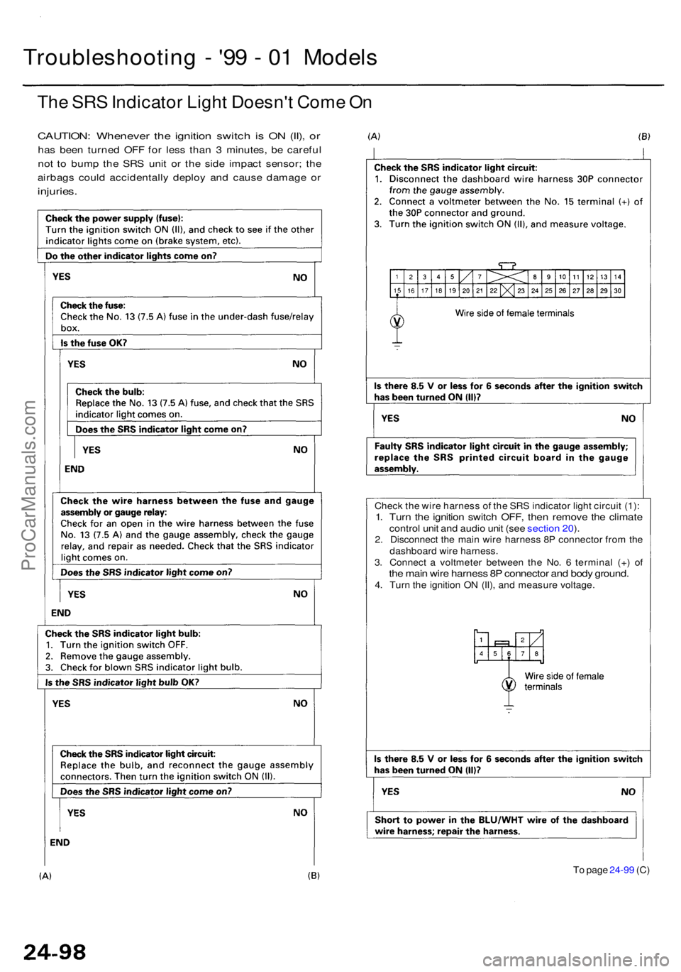
The SR S Indicato r Ligh t Doesn' t Com e O n
CAUTION : Wheneve r th e ignitio n switc h is O N (II) , o r
ha s bee n turne d OF F fo r les s tha n 3 minutes , b e carefu l
no t t o bum p th e SR S uni t o r th e sid e impac t sensor ; th e
airbag s coul d accidentall y deplo y an d caus e damag e o r
injuries .
Troubleshootin g - '9 9 - 0 1 Model s
Check th e wir e harnes s o f th e SR S indicato r ligh t circui t (1) :1. Tur n th e ignitio n switc h OFF , the n remov e th e climat econtrol uni t an d audi o uni t (se e sectio n 20 ).2 . Disconnec t th e mai n wir e harnes s 8 P connecto r fro m th e
dashboar d wir e harness .
3 . Connec t a voltmete r betwee n th e No . 6 termina l (+ ) o f
the mai n wir e harnes s 8 P connecto r an d bod y ground .4. Tur n th e ignitio n O N (II) , an d measur e voltage .
T o pag e 24-9 9 (C )
ProCarManuals.com
Page 1871 of 1954
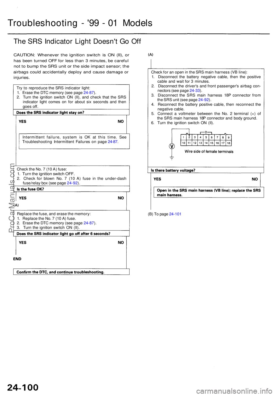
(B) T o pag e 24-10 1
Replac
e th e fuse , an d eras e th e memory :
1 . Replac e th e No . 7 (1 0 A ) fuse .
2 . Eras e th e DT C memor y (se e pag e 24-87 ).
3 . Tur n th e ignitio n switc h O N (II) .
Chec
k th e No . 7 (1 0 A ) fuse :
1. Tur n th e ignitio n switc h OFF .2. Chec k fo r blow n No . 7 (1 0 A ) fus e i n th e under-das h
fuse/rela y bo x (se e pag e 24-92 ).
Intermitten
t failure , syste m is O K a t thi s time . Se e
Troubleshootin g Intermitten t Failure s o n pag e 24-87 . Chec
k fo r a n ope n in th e SR S mai n harnes s (V B line) :
1 . Disconnec t th e batter y negativ e cable , the n th e positiv e
cabl e an d wai t fo r 3 minutes .
2 . Disconnec t th e driver' s an d fron t passenger' s airba g con -
nector s (se e pag e 24-33 ).
3 . Disconnec t th e SR S mai n harnes s 18 P connecto r fro m
th e SR S uni t (se e pag e 24-92 ).
4 . Reconnec t th e batter y positiv e cable , the n reconnec t th e
negativ e cable .
5 . Connec t a voltmete r betwee n th e No . 2 termina l (+ ) o f
th e SR S mai n harnes s 18 P connecto r an d bod y ground .
6 . Tur n th e ignitio n switc h O N (II) .
Tr
y t o reproduc e th e SR S indicato r light :
1 . Eras e th e DT C memor y (se e pag e 24-87 ).
2 . Tur n th e ignitio n switc h O N (II) , an d chec k tha t th e SR S
indicato r ligh t come s o n fo r abou t si x second s an d the n
goe s off .
The SR S Indicato r Ligh t Doesn' t G o Of f
CAUTION : Wheneve r th e ignitio n switc h i s O N (II) , o r
ha s bee n turne d OF F fo r les s tha n 3 minutes , b e carefu l
not t o bum p th e SR S uni t o r th e sid e impac t sensor ; th e
airbag s coul d accidentall y deplo y an d caus e damag e o r
injuries .
Troubleshootin g - '9 9 - 0 1 Model s
ProCarManuals.com
Page 1875 of 1954
Troubleshooting - '9 9 - 0 1 Model s
DTC 1- 1 an d DT C 1- 2
CAUTION : Wheneve r th e ignitio n switc h is O N (II) , o r ha s
bee n turne d OF F fo r les s tha n 3 minutes , b e carefu l no t
to bum p th e SR S uni t o r th e sid e impac t sensor ; th e
airbag s coul d accidentall y deplo y an d caus e damag e o r
injuries .
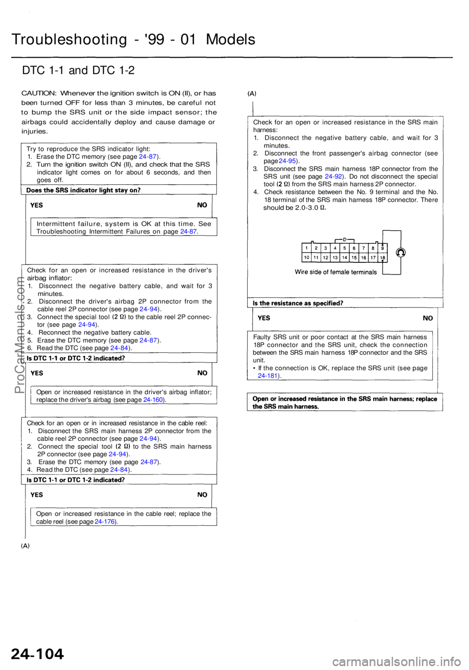
Try t o reproduc e th e SR S indicato r light :
1 . Eras e th e DT C memor y (se e pag e 24-87 ).
2 . Tur n th e ignitio n switc h O N (II) , an d chec k tha t th e SR Sindicato r ligh t come s o n fo r abou t 6 seconds , an d the n
goe s off . Chec
k fo r a n ope n o r increase d resistanc e in th e SR S mai n
harness :
1 . Disconnec t th e negativ e batter y cable , an d wai t fo r 3
minutes .2. Disconnec t th e fron t passenger' s airba g connecto r (se e
pag e 24-95 ).
3 . Disconnec t th e SR S mai n harnes s 18 P connecto r fro m th e
SR S uni t (se e pag e 24-92 ). D o no t disconnec t th e specia l
tool fro m th e SR S mai n harnes s 2 P connector .
4 . Chec k resistanc e betwee n th e No . 9 termina l an d th e No .
1 8 termina l o f th e SR S mai n harnes s 18 P connector . Ther e
should b e 2.0-3. 0
Intermitten t failure , syste m is O K a t thi s time . Se eTroubleshootin g Intermitten t Failure s o n pag e 24-87 .
Chec k fo r a n ope n o r increase d resistanc e i n th e driver' s
airbag inflator :1. Disconnec t th e negativ e batter y cable , an d wai t fo r 3minutes .2. Disconnec t th e driver' s airba g 2 P connecto r fro m th e
cabl e ree l 2 P connecto r (se e pag e 24-94 ).
3 . Connec t th e specia l too l t o th e cabl e ree l 2 P connec -tor (se e pag e 24-94 ).4 . Reconnec t th e negativ e batter y cable .
5 . Eras e th e DT C memor y (se e pag e 24-87 ).
6 . Rea d th e DT C (se e pag e 24-84 ).
Ope n o r increase d resistanc e in th e driver' s airba g inflator ;
replac e th e driver' s airba g (se e pag e 24-160 ).
Chec k fo r a n ope n o r i n increase d resistanc e in th e cabl e reel :
1 . Disconnec t th e SR S mai n harnes s 2 P connecto r fro m th e
cabl e ree l 2 P connecto r (se e pag e 24-94 ).
2 . Connec t th e specia l too l t o th e SR S mai n harnes s
2 P connecto r (se e pag e 24-94 ).
3 . Eras e th e DT C memor y (se e pag e 24-87 ).
4 . Rea d th e DT C (se e pag e 24-84 ).
Ope n o r increase d resistanc e in th e cabl e reel ; replac e th e
cabl e ree l (se e pag e 24-176 ). Fault
y SR S uni t o r poo r contac t a t th e SR S mai n harnes s
18 P connecto r an d th e SR S unit , chec k th e connectio n
betwee n th e SR S mai n harnes s 18 P connecto r an d th e SR S
unit .
• I f th e connectio n is OK , replac e th e SR S uni t (se e pag e
24-181 ).
ProCarManuals.com
Page 1876 of 1954
DTC 1- 3
CAUTION : Wheneve r th e ignitio n switc h i s O N (II) , o r ha s
bee n turne d OF F fo r les s tha n 3 minutes , b e carefu l no t
t o bum p th e SR S uni t o r th e sid e impac t sensor ; th e
airbag s coul d accidentall y deplo y an d caus e damag e o r
injuries .
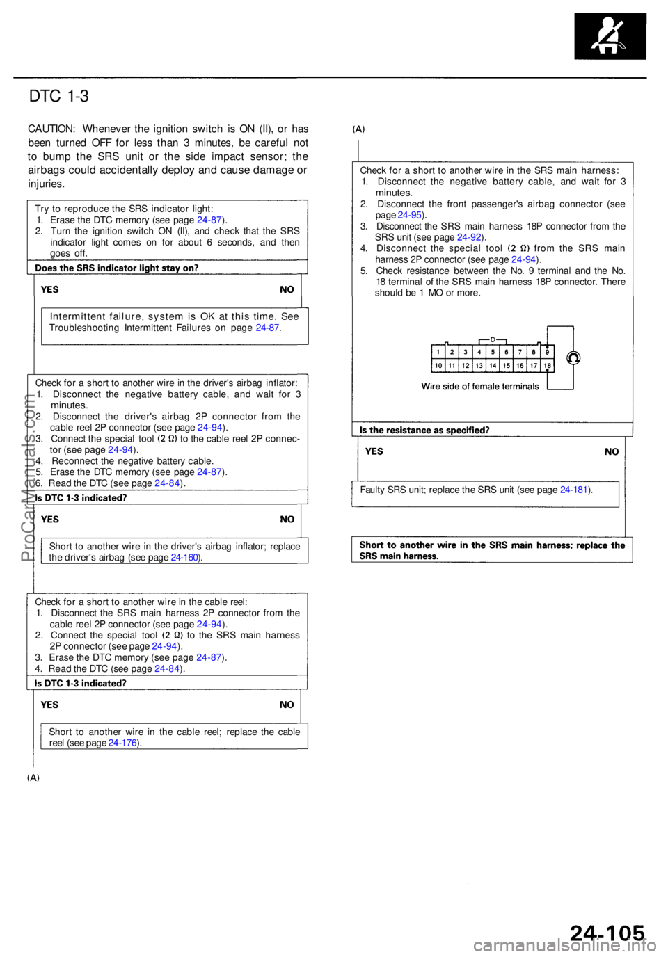
Check fo r a shor t t o anothe r wir e in th e SR S mai n harness :
1 . Disconnec t th e negativ e batter y cable , an d wai t fo r 3
minutes .2. Disconnec t th e fron t passenger' s airba g connecto r (se e
pag e 24-95 ).
3 . Disconnec t th e SR S mai n harnes s 18 P connecto r fro m th e
SR S uni t (se e pag e 24-92 ).
4 . Disconnec t th e specia l too l fro m th e SR S mai n
harnes s 2 P connecto r (se e pag e 24-94 ).
5 . Chec k resistanc e betwee n th e No . 9 termina l an d th e No .
1 8 termina l o f th e SR S mai n harnes s 18 P connector . Ther e
shoul d b e 1 M O o r more .
Tr
y t o reproduc e th e SR S indicato r light :
1 . Eras e th e DT C memor y (se e pag e 24-87 ).
2 . Tur n th e ignitio n switc h O N (II) , an d chec k tha t th e SR S
indicato r ligh t come s o n fo r abou t 6 seconds , an d the n
goe s off .
Intermitten t failure , syste m is O K a t thi s time . Se eTroubleshootin g Intermitten t Failure s o n pag e 24-87 .
Chec k fo r a shor t t o anothe r wir e in th e driver' s airba g inflator :
1 . Disconnec t th e negativ e batter y cable , an d wai t fo r 3
minutes .2. Disconnec t th e driver' s airba g 2 P connecto r fro m th e
cabl e ree l 2 P connecto r (se e pag e 24-94 ).
3 . Connec t th e specia l too l t o th e cabl e ree l 2 P connec -
to r (se e pag e 24-94 ).
4 . Reconnec t th e negativ e batter y cable .
5 . Eras e th e DT C memor y (se e pag e 24-87 ).
6 . Rea d th e DT C (se e pag e 24-84 ).
Shor t t o anothe r wir e i n th e driver' s airba g inflator ; replac e
th e driver' s airba g (se e pag e 24-160 ).
Chec k fo r a shor t t o anothe r wir e in th e cabl e reel :
1 . Disconnec t th e SR S mai n harnes s 2 P connecto r fro m th e
cabl e ree l 2 P connecto r (se e pag e 24-94 ).
2 . Connec t th e specia l too l t o th e SR S mai n harnes s
2 P connecto r (se e pag e 24-94 ).
3 . Eras e th e DT C memor y (se e pag e 24-87 ).
4 . Rea d th e DT C (se e pag e 24-84 ). Fault
y SR S unit ; replac e th e SR S uni t (se e pag e 24-181 ).
Shor t t o anothe r wir e i n th e cabl e reel ; replac e th e cabl e
ree l (se e pag e 24-176 ).
ProCarManuals.com