1996 ACURA RL KA9 sensor
[x] Cancel search: sensorPage 1538 of 1954
Lighting Syste m
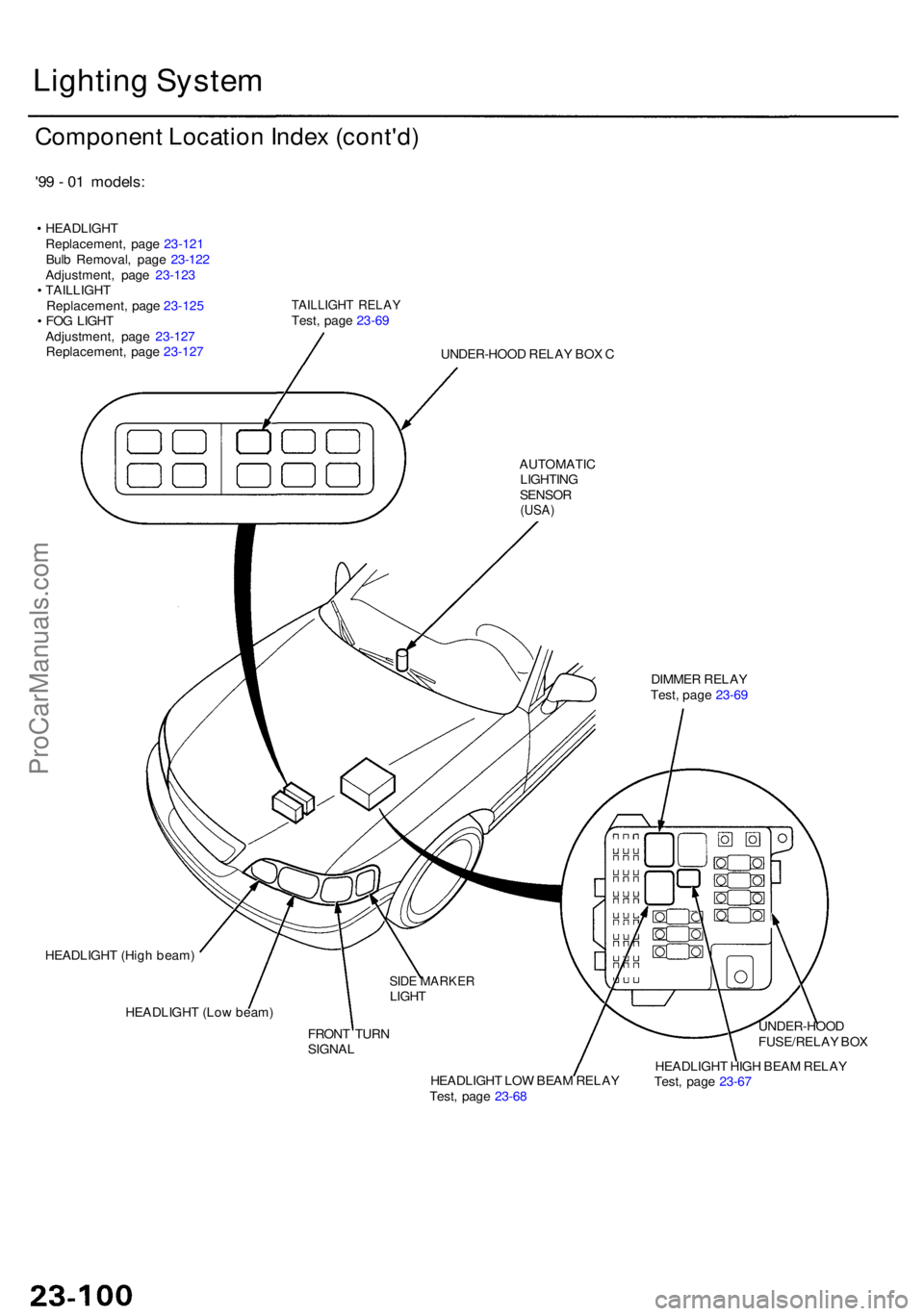
Componen t Locatio n Inde x (cont'd )
'99 - 0 1 models :
• HEADLIGH T
Replacement , pag e 23-12 1
Bul b Removal , pag e 23-12 2
Adjustment , pag e 23-12 3
• TAILLIGH T
Replacement , pag e 23-12 5
• FO G LIGH T
Adjustment , pag e 23-12 7
Replacement , pag e 23-12 7
TAILLIGH T RELA YTest, pag e 23-6 9
UNDER-HOO D RELA Y BO X C
AUTOMATI C
LIGHTIN G
SENSOR(USA)
DIMME R RELA Y
Test , pag e 23-6 9
HEADLIGH T (Hig h beam )
HEADLIGH T (Lo w beam )
FRONT TUR N
SIGNA L
SIDE MARKE RLIGHT
HEADLIGH T LO W BEA M RELA Y
Test , pag e 23-6 8 HEADLIGH
T HIG H BEA M RELA Y
Test , pag e 23-6 7UNDER-HOO
D
FUSE/RELA Y BO X
ProCarManuals.com
Page 1541 of 1954
BLK/YEL
YEL/BLK
BLU/RE D
BLK
WHT/YE L
GRN/BLU
GRN/YE L
RED/GR N
Ignition switc h O N (II )
Unde r al l condition s
Under al l condition s
Under al l condition s
Driver' s doo r ope n
Combinatio n ligh t
switc h O N
(Excep t "AUTO" )
Unde r al l condition sChec
k fo r voltag e to ground :
Ther e shoul d b e batter y voltage .
Chec k fo r voltag e to ground:
Ther e shoul d b e batter y voltage .
Check fo r continuit y to ground :
There shoul d b e continuity .
Chec k fo r voltag e to ground :
There shoul d b e batter y voltage .
Check fo r voltag e t o ground :
Ther e shoul d b e 1 V or less .
Chec k fo r continuit y t o ground :
Ther e shoul d b e continuity .
Chec k fo r voltag e to ground :
Ther e shoul d b e batter y voltage .•
Blow n No . 2 0 (2 0 A ) fus e in th e
under-das h fuse/rela y bo x
• A n ope n in th e wir e
• Blow n No . 1 9 (7. 5 A ) fus e in th e
under-das h fuse/rela y bo x
• A n ope n in th e wir e
• Fault y headligh t rela y
• A n ope n in th e wir e
• Poo r groun d (G401 , G402 , G651 )
• A n ope n in th e wir e
• Blow n No . 5 6 (7. 5 A ) fus e in th e
under-hoo d fuse/rela y bo x
• A n ope n in th e wir e
• Fault y driver' s doo r switc h
• Poo r groun d (G401 , G402 )
• A n ope n in th e wir e
• Fault y combinatio n ligh t switc h
• Poo r ground (G401, G402 )
• A n ope n in th e wir e
• Fault y tailligh t rela y
• A n ope n in th e wir e
• Blow n No . 1 (1 5 A ) fus e in th e
under-das h fuse/rela y bo x
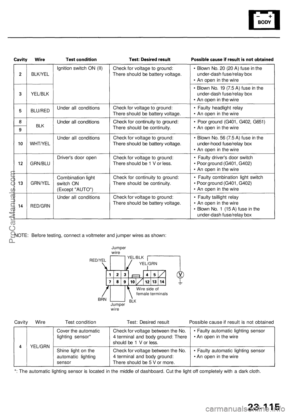
NOTE : Befor e testing , connec t a voltmete r an d jumpe r wire s a s shown :
JumperwireYEL/BL K
YEL/GR N
Wire sid e o f
femal e terminal s
BLKJumpe r
wir eBRN
RED/YE L
Cavity Wir e Tes t conditio n Test : Desire d resul t Possibl e caus e if resul t i s no t obtaine d
YEL/GR N
Cover th e automati c
lightin g sensor *
Shin e ligh t o n th e
automati c lightin g
sensor
Check fo r voltag e betwee n th e No .
4 termina l an d bod y ground : Ther e
shoul d b e 1 V or less .
Chec k fo r voltag e betwee n th e No .
4 termina l an d bod y ground :
Ther e shoul d b e 5 V or more . •
Fault y automati c lightin g senso r
• A n ope n in th e wir e
• Fault y automati c lightin g senso r
• A n ope n in th e wir e
* : Th e automati c lightin g senso r i s locate d i n th e middl e o f dashboard . Cu t th e ligh t of f completel y wit h a dar k cloth .
ProCarManuals.com
Page 1588 of 1954
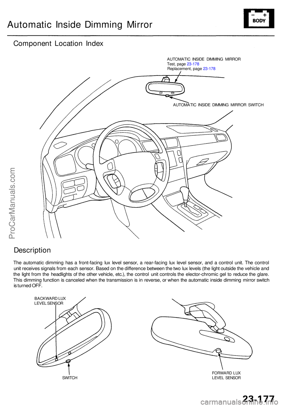
Automatic Insid e Dimmin g Mirro r
Componen t Locatio n Inde x
AUTOMATI C INSID E DIMMIN G MIRRO R
Test , pag e 23-17 8
Replacement , pag e 23-17 8
AUTOMATI C INSID E DIMMIN G MIRRO R SWITC H
Descriptio n
The automati c dimmin g ha s a front-facin g lu x leve l sensor , a rear-facin g lu x leve l sensor , an d a contro l unit . Th e contro l
uni t receive s signal s fro m eac h sensor . Base d o n th e differenc e betwee n th e tw o lu x level s (th e ligh t outsid e th e vehicl e an d
th e ligh t fro m th e headlight s o f th e othe r vehicle , etc.) , th e contro l uni t control s th e elector-chromi c ge l t o reduc e th e glare .
Thi s dimmin g functio n is cancele d whe n th e transmissio n is in reverse , o r whe n th e automati c insid e dimmin g mirro r switc h
i s turne d OFF .
BACKWAR D LU XLEVE L SENSO R
SWITC H
FORWAR D LU XLEVE L SENSO R
ProCarManuals.com
Page 1601 of 1954
Driving Positio n Memor y Syste m (DPMS )
Descriptio n
The driver' s seat , th e powe r mirror s an d th e steerin g column , whos e position s ar e determine d th e driver' s position , hav e
a memor y feature . Th e sea t adjustments , th e mirro r adjustments , an d th e steerin g colum n adjustment s can be regulate d
separately . Al l o f adjustment s ca n b e memorize d b y th e pressin g th e MEM O butto n o n th e drivin g positio n memor y
switch , an d the n pressin g on e o f th e tw o positio n button s withi n 5 seconds . Pressin g th e appropriat e positio n butto n wil l
mov e th e seat , th e mirro r an d th e steerin g colum n t o th e positio n memorize d fo r drive r 1 o r drive r 2 , eliminatin g manua l
adjustment s whe n changin g drivers .
NOTE : Disconnectin g th e batter y wil l cance l th e memorize d positions .
STEERIN G COLUM N POSITIO N SENSOR S
B y mean s o f th e variabl e resistor-typ e til t positio n senso r an d extend-retrac t positio n sensor , th e steerin g colum n contro l
uni t detect s th e voltag e change s cause d b y th e movement s o f th e steerin g column . Thes e voltag e change s ar e store d in
memory , an d th e steerin g colum n positio n is memorized .
POWE R SEA T POSITIO N SENSOR S
Eac h moto r ha s a ree d switc h senso r whic h detect s moto r rotatio n an d send s a puls e to th e powe r sea t contro l uni t whe n
th e moto r rotates . Th e contro l uni t store s th e numbe r o f pulse s i n it s memory , an d th e sea t positio n is memorized .
POWE R MIRRO R POSITIO N SENSOR S
B y mean s o f a Hall-effec t typ e til t positio n senso r an d swin g positio n sensor , th e powe r mirro r contro l uni t detect s th e
voltag e change s cause d b y th e movement s o f th e mirrors .
Thes e voltag e change s ar e store d in memory , an d th e powe r mirro r position s ar e memorized .
"AUTO " SWITC H FUNCTIO N
Whe n th e ignitio n ke y i s pulle d ou t (ignitio n switc h turne d OFF ) wit h th e AUT O switc h i n th e steerin g colum n switc h O N
and th e vehicl e parke d (shif t leve r i n th e steerin g colum n wil l automaticall y mov e t o th e highes t til t positio n an d full y
retracte d positio n t o eas e exi t fro m th e vehicle .
Whe n th e ignitio n ke y i s inserte d int o th e ignitio n ke y switc h wit h th e AUT O switc h O N an d th e vehicl e parke d (shif t leve r
in th e steerin g colum n wil l automaticall y mov e bac k t o th e previou s position .
MEMOR Y RETRIEV E
When on e o f th e tw o button s o n th e drivin g positio n memor y switc h i s presse d wit h th e vehicl e parke d (shif t leve r i n
th e seat , th e mirror , an d th e steerin g colum n mov e t o th e memorize d positions .
ProCarManuals.com
Page 1609 of 1954
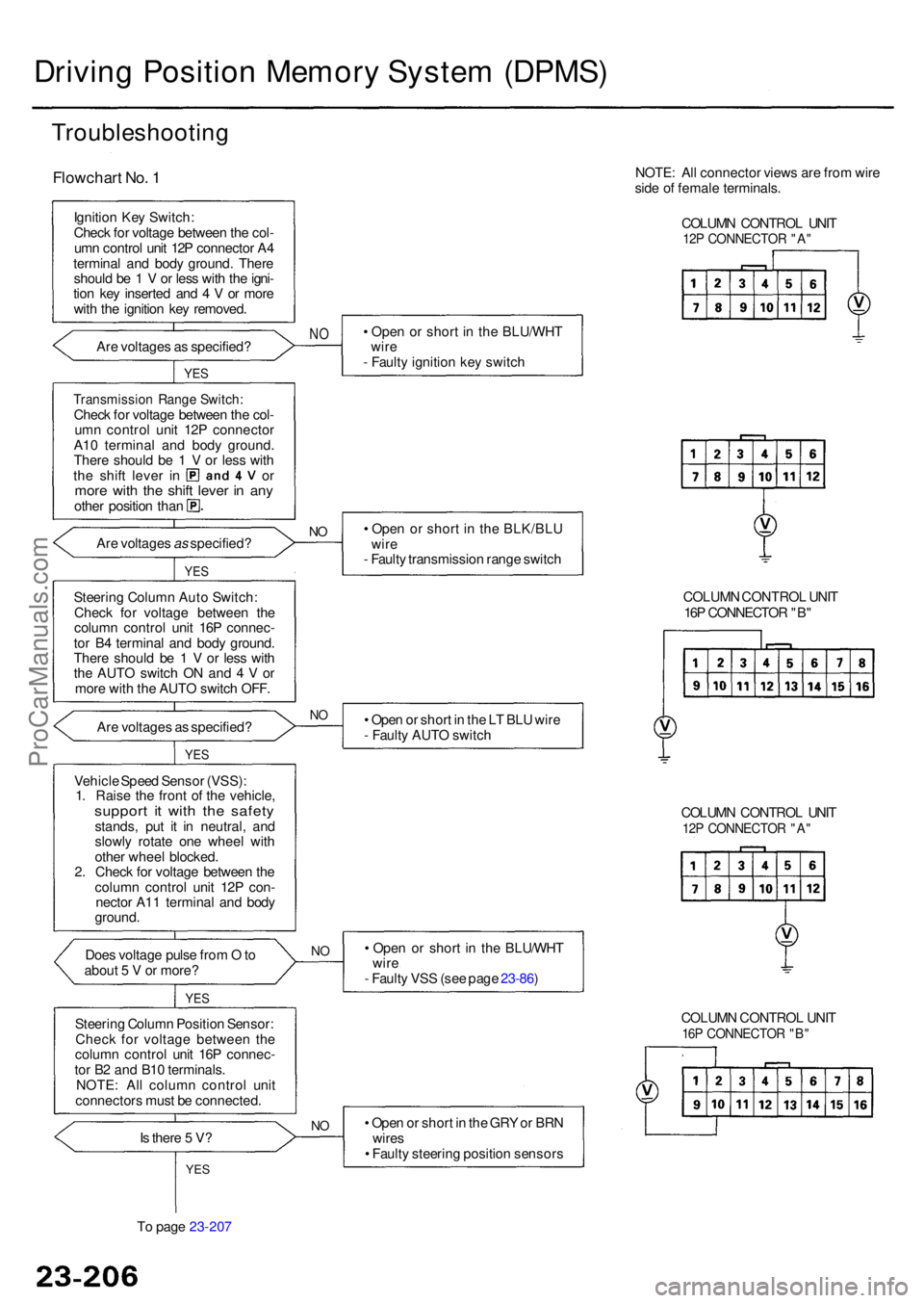
To pag e 23-207
Drivin g Positio n Memor y Syste m (DPMS )
Troubleshootin g
Flowchart No . 1
Ignitio n Ke y Switch :
Chec k fo r voltag e betwee n th e col -
um n contro l uni t 12 P connecto r A 4
termina l an d bod y ground . Ther e
shoul d b e 1 V or les s wit h th e igni -
tio n ke y inserte d an d 4 V or mor e
wit h th e ignitio n ke y removed .
• Ope n o r shor t i n th e BLU/WH T
wir e
- Fault y ignitio n ke y switc h
Ar
e voltage s a s specified ?
NO
YE S
Transmissio n Rang e Switch :Check fo r voltag e betwee n th e col -
um n contro l uni t 12 P connecto r
A1 0 termina l an d bod y ground .
Ther e shoul d b e 1 V or les s wit h
the shif t leve r i n o rmore wit h th e shif t leve r i n an yothe r positio n tha n
• Ope n o r shor t i n th e BLK/BL U
wir e
- Fault y transmissio n rang e switc h
NOAr e voltage s as specified ?
YES
Steerin g Colum n Aut o Switch :
Chec k fo r voltage betwee n th e
colum n contro l uni t 16 P connec -
to r B 4 termina l an d bod y ground .
Ther e shoul d b e 1 V or les s wit h
th e AUT O switc h O N an d 4 V or
mor e wit h th e AUT O switc h OFF .
Ar e voltage s a s specified ?
NO• Ope n o r shor t in th e L T BL U wir e
- Fault y AUT O switc h
YES
Vehicl e Spee d Senso r (VSS) :
1 . Rais e th e fron t o f th e vehicle ,
support i t wit h th e safet ystands , pu t i t i n neutral , an d
slowl y rotat e on e whee l wit h
othe r whee l blocked .
2 . Chec k fo r voltag e betwee n th e
colum n contro l uni t 12 P con -
necto r A1 1 termina l an d bod y
ground .
Doe s voltag e puls e fro m O to
abou t 5 V or more ? •
Ope n o r shor t i n th e BLU/WH T
wir e
- Fault y VS S (se e pag e 23-86 )
NO
YE S
Steerin g Colum n Positio n Sensor :
Chec k fo r voltag e betwee n th e
column contro l uni t 16 P connec -
to r B 2 an d B1 0 terminals .
NOTE : Al l colum n contro l uni t
connector s mus t b e connected .
I s ther e 5 V ?
NO • Ope n o r shor t in th e GR Y o r BR N
wire s
• Fault y steerin g positio n sensor s
YES
COLUM N CONTRO L UNI T16P CONNECTO R "B "
COLUM N CONTRO L UNI T12P CONNECTO R "A "
COLUM N CONTRO L UNI T
16 P CONNECTO R "B "
NOTE
: Al l connecto r view s ar e fro m wire
sid e o f femal e terminals .
COLUM N CONTRO L UNI T
12P CONNECTO R "A "
ProCarManuals.com
Page 1610 of 1954
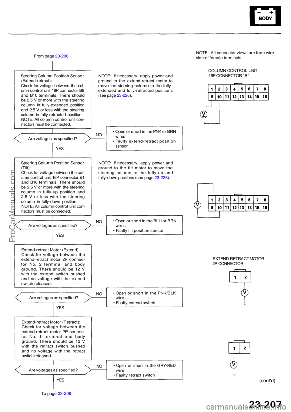
From pag e 23-206
Steerin g Colum n Positio n Senso r
(Extend-retract) :Check fo r voltag e betwee n th e col -
um n contro l uni t 16 P connecto r B 9
an d B1 0 terminals . Ther e shoul d
b e 2. 5 V or mor e wit h th e steerin g
colum n i n fully-extende d positio n
and 2. 5 V or les s wit h th e steerin gcolumn in fully-retracte d position .
NOTE : Al l colum n contro l uni t con -
nector s mus t b e connected . NOTE
: I f necessary , appl y powe r an d
groun d t o th e extend-retrac t moto r t o
mov e th e steerin g colum n t o th e fully -extende d an d fully-retracte d position s(see pag e 23-226 ).
Ar e voltage s a s specified ? •
Ope n o r shor t i n th e PN K o r BR Nwire s• Fault y extend-retrac t positio nsensor
NO
YE S
NOTE : I f necessary , appl y powe r an d
groun d to th e tilt moto r to mov e thesteerin g colum n t o th e fully-u p an d
fully-dow n position s (se e pag e 23-226 ).
Steerin
g Colum n Positio n Senso r
(Tilt) :
Chec k fo r voltag e betwee n th e col -
um n contro l uni t 16 P connecto r B 1
an d B1 0 terminals . Ther e shoul d
b e 2. 5 V or mor e wit h th e steerin g
colum n i n fully-u p positio n an d
2. 5 V or les s wit h th e steerin g
column in fully-dow n position .
NOTE : Al l colum n contro l uni t con -
nector s mus t b e connected .
Ar e voltage s a s specified ?
NO• Ope n o r shor t i n th e BL U o r BR Nwire s• Fault y til t positio n senso r
Extend-retrac t Moto r (Extend) :
Chec k fo r voltag e betwee n th e
extend-retrac t moto r 2 P connec -
to r No . 2 termina l an d bod y
ground . Ther e shoul d b e 1 2 V
wit h th e exten d switc h pushe d
an d n o voltag e wit h th e exten d
switch released .
Are voltage s a s specified ? •
Ope n o r shor t i n th e PNK/BL K
wir e
• Fault y exten d switc hNO
YE S
Extend-retrac t Moto r (Retract) :
Chec k fo r voltag e betwee n th e
extend-retrac t moto r 2 P connec -tor No . 1 termina l an d bod y
ground . Ther e shoul d b e 1 2 V
wit h th e retrac t switc h pushe d
an d n o voltag e wit h th e retrac t
switc h released .
Ar e voltage s a s specified ?
NO• Ope n o r shor t i n th e GRY/RE Dwire• Fault y retrac t switc h
T o pag e 23-208YE S(cont'd )
NOTE: Al l connecto r view s ar e fro m wir e
sid e o f femal e terminals .
COLUM N CONTRO L UNI T
16 P CONNECTO R "B "
EXTEND-RETRAC T MOTO R
2P CONNECTO R
ProCarManuals.com
Page 1613 of 1954
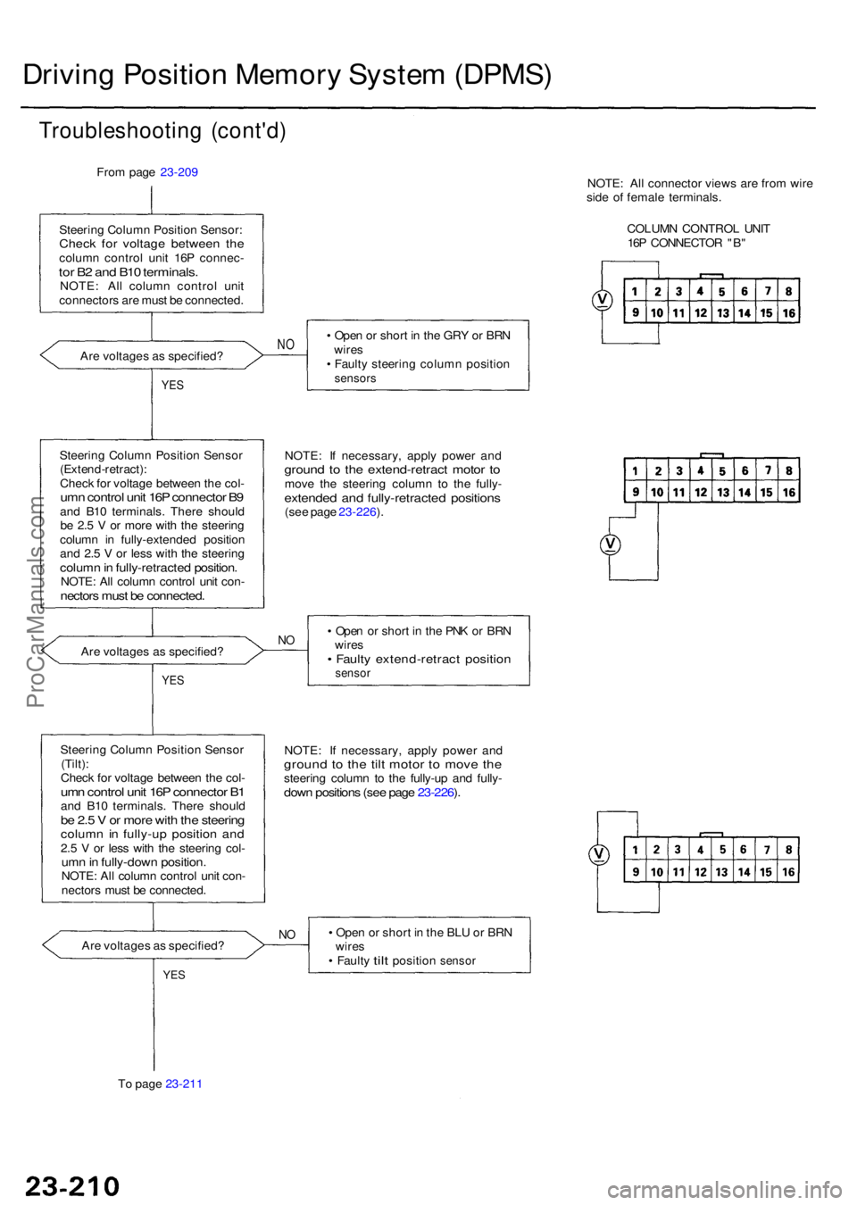
Driving Positio n Memor y Syste m (DPMS )
Troubleshootin g (cont'd )
From pag e 23-209
Steerin g Colum n Positio n Sensor :
Check fo r voltag e betwee n th ecolum n contro l uni t 16 P connec -tor B 2 an d B1 0 terminals .NOTE: Al l colum n contro l uni t
connector s ar e mus t b e connected .
Ar e voltage s a s specified ? •
Ope n o r shor t i n th e GR Y o r BR N
wire s
• Fault y steerin g colum n positio n
sensors
NO
YE S
NOTE : I f necessary , appl y powe r an dgroun d t o th e extend-retrac t moto r t omov e th e steerin g colum n t o th e fully -extende d an d fully-retracte d position s(see pag e 23-226 ).
Steerin
g Colum n Positio n Senso r
(Extend-retract) :
Chec k fo r voltag e betwee n th e col -umn contro l uni t 16 P connecto r B 9an d B1 0 terminals . Ther e shoul d
b e 2. 5 V or mor e wit h th e steerin g
colum n i n fully-extende d positio n
an d 2. 5 V or les s wit h th e steerin g
column in fully-retracte d position .NOTE: Al l colum n contro l uni t con -nector s mus t b e connected .
• Ope n o r shor t i n th e PN K o r BR N
wire s
• Fault y extend-retrac t positio nsensor
NOAr e voltage s a s specified ?
YES
NOTE : I f necessary , appl y powe r an dgroun d t o th e til t moto r t o mov e th esteerin g colum n t o th e fully-u p an d fully -down position s (se e pag e 23-226 ).
Steerin g Colum n Positio n Senso r
(Tilt) :
Chec k fo r voltag e betwee n th e col -
umn contro l uni t 16 P connecto r B 1an d B1 0 terminals . Ther e shoul dbe 2. 5 V or mor e wit h th e steerin gcolumn i n fully-u p positio n an d2.5 V or les s wit h th e steerin g col -umn in fully-dow n position .NOTE: Al l colum n contro l uni t con -
nector s mus t b e connected .
Ar e voltage s a s specified ?
NO• Ope n o r shor t i n th e BL U o r BR N
wire s
• Fault y tilt positio n sensor
To page 23-211
YES
NOTE : Al l connecto r view s ar e fro m wir e
sid e o f femal e terminals .
COLUM N CONTRO L UNI T
16 P CONNECTO R "B "
ProCarManuals.com
Page 1614 of 1954
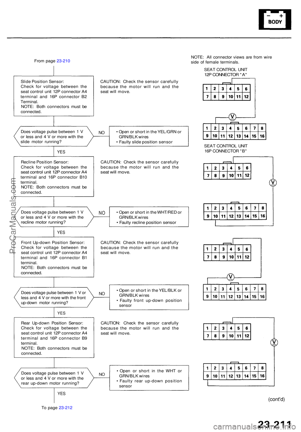
From pag e 23-210
CAUTION: Chec k th e senso r carefull y
becaus e th e moto r wil l ru n an d th e
sea t wil l move .
Slid
e Positio n Sensor :
Chec k fo r voltag e betwee n th e
sea t contro l uni t 12 P connecto r A 4
termina l an d 16 P connecto r B 2
Terminal .
NOTE : Bot h connector s mus t b e
connected . NOTE
: Al l connecto r view s ar e fro m wir e
sid e o f femal e terminals .
SEA T CONTRO L UNI T
12P CONNECTO R "A "
Doe s voltag e puls e betwee n 1 V
o r les s an d 4 V or mor e wit h th e
slid e moto r running ? •
Ope n o r shor t i n th e YEL/GR N o r
GRN/BL K wire s
• Fault y slid e positio n senso rNO
YE S
Reclin e Positio n Sensor :
Chec k fo r voltag e betwee n th e
sea t contro l uni t 12 P connecto r A 4termina l an d 16 P connecto r B1 0
terminal .
NOTE : Bot h connector s mus t b e
connected . CAUTION
: Chec k th e senso r carefully
becaus e th e moto r wil l ru n an d th esea t wil l move .
• Ope n o r shor t i n th e WHT/RE D o r
GRN/BL K wire s
• Fault y reclin e positio n senso r
NODoe s voltag e puls e betwee n 1 V
o r les s an d 4 V or mor e wit h th e
reclin e moto r running ?
Front Up-dow n Positio n Sensor :
Chec k fo r voltag e betwee n th e
sea t contro l uni t 12 P connecto r A 4
termina l an d 16 P connecto r B 1
terminal .
NOTE : Bot h connector s mus t b e
connected .
YES
CAUTION : Chec k th e senso r carefullybecaus e th e moto r wil l ru n an d th esea t wil l move .
Doe s voltag e puls e betwee n 1 V or
les s an d 4 V or mor e wit h th e fron t
up-dow n moto r running ?
NO• Ope n o r shor t i n th e YEL/BL K o r
GRN/BL K wire s
• Fault y fron t up-dow n positio n
sensor
YES
CAUTION : Chec k th e senso r carefull y
becaus e th e moto r wil l ru n an d th e
sea t wil l move .
Rea
r Up-dow n Positio n Sensor :
Chec k fo r voltag e betwee n th e
sea t contro l uni t 12 P connecto r A 4
termina l an d 16 P connecto r B 9
terminal .
NOTE : Bot h connector s mus t b e
connected .
• Ope n o r shor t i n th e WH T o r
GRN/BL K wire s
• Fault y rea r up-dow n positio n
sensor
NODoe s voltag e puls e betwee n 1 V
o r les s an d 4 V or mor e wit h th e
rea r up-dow n moto r running ?
YES
To pag e 23-212
(cont'd )
SEAT CONTRO L UNI T
16 P CONNECTO R "B "
ProCarManuals.com