Page 1503 of 2543
Torque: 64 NVm (650 kgfVcm, 47 ftVlbf)
13. California only:
INSTALL VSV FOR FUEL PRESSURE CONTROL
14. INSTALL INTAKE AIR CONNECTOR PIPE
15. CONNECT CONTROL CABLES TO THROTTLE BODY
16. FILL WITH ENGINE COOLANT
17. CHECK FOR FUEL LEAKS
(See item 5 in fuel system in precaution)
FUEL PRESSURE PULSATION DAMPER
COMPONENTS FOR REMOVAL AND
INSTALLATION
FUEL PRESSURE PULSATION DAMPER
REMOVAL
1. REMOVE STARTER
(See starter removal in Starting System)
2. REMOVE FUEL PRESSURE PULSATION DAMPER
(a) Remove the pulsation damper and upper gasket.
(b) Disconnect the fuel inlet pipe from the fuel pipe support, and
remove the lower gasket.
± ENGINESFI SYSTEM (2JZ±GE)EG±213
Page 1504 of 2543
FUEL PRESSURE PULSATION DAMPER
INSTALLATION
1. INSTALL FUEL PRESSURE PULSATION DAMPER
(a) Install the fuel inlet pipe and pulsation damper with 2 new
gaskets.
HINT: Different sized gaskets are used for the upper (large
size) and lower (small size).
(b) Using SST, tighten the pulsation damper.
SST 09612±24014 (09617±24011)
Torque:
41 NVm (420 kgfVcm, 30 ftVlbf)
35 NVm (350 kgfVcm, 25 ftVlbf) for SST
HINT: Use a torque wrench with a fulcrum length of 30 cm
(11.81 in.).
2. INSTALL STARTER
(See starter installation in Starting System)
4. CHECK FOR FUEL LEAKS
(See item 5 in fuel system in precaution) EG±214
± ENGINESFI SYSTEM (2JZ±GE)
Page 1505 of 2543
FUEL TANK AND LINE
COMPONENTS
± ENGINESFI SYSTEM (2JZ±GE)EG±215
Page 1506 of 2543
PRECAUTIONS
1. Always use new gaskets when replacing the fuel tank or
component parts.
2. Apply the proper torque to all parts tightened.
FUEL LINES AND CONNECTIONS
INSPECTION
(a) Check the fuel lines for cracks or leakage, and all
connections for deformation.
(b) C h e c k t h e f u e l t a n k vapor vent system hoses and
connections for looseness, sharp bends or damage.
(c) Check the fuel tank for deformation, cracks, fuel leakage or
tank band looseness.
(d) Check the filler neck for damage or fuel leakage.
(e) Hose and tube connections are as shown in the illustration.
If a problem is found, repair or replace the part as necessary. EG±216
± ENGINESFI SYSTEM (2JZ±GE)
Page 1522 of 2543

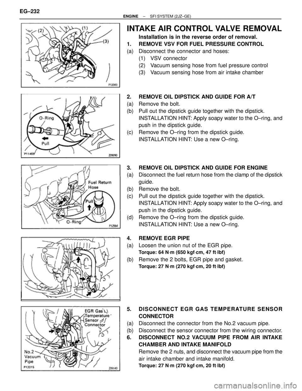
INTAKE AIR CONTROL VALVE REMOVAL
Installation is in the reverse order of removal.
1. REMOVE VSV FOR FUEL PRESSURE CONTROL
(a) Disconnect the connector and hoses:
(1) VSV connector
(2) Vacuum sensing hose from fuel pressure control
(3) Vacuum sensing hose from air intake chamber
2. REMOVE OIL DIPSTICK AND GUIDE FOR A/T
(a) Remove the bolt.
(b) Pull out the dipstick guide together with the dipstick.
INSTALLATION HINT: Apply soapy water to the O±ring, and
push in the dipstick guide.
(c) Remove the O±ring from the dipstick guide.
INSTALLATION HINT: Use a new O±ring.
3. REMOVE OIL DIPSTICK AND GUIDE FOR ENGINE
(a) Disconnect the fuel return hose from the clamp of the dipstick
guide.
(b) Remove the bolt.
(c) Pull out the dipstick guide together with the dipstick.
INSTALLATION HINT: Apply soapy water to the O±ring, and
push in the dipstick guide.
(d) Remove the O±ring from the dipstick guide.
INSTALLATION HINT: Use a new O±ring.
4. REMOVE EGR PIPE
(a) Loosen the union nut of the EGR pipe.
Torque: 64 NVm (650 kgfVcm, 47 ftVlbf)
(b) Remove the 2 bolts, EGR pipe and gasket.
Torque: 27 NVm (270 kgfVcm, 20 ftVlbf)
5. DISCONNECT EGR GAS TEMPERATURE SENSOR
CONNECTOR
(a) Disconnect the connector from the No.2 vacuum pipe.
(b) Disconnect the sensor connector from the wiring connector.
6. DISCONNECT NO.2 VACUUM PIPE FROM AIR INTAKE
CHAMBER AND INTAKE MANIFOLD
Remove the 2 nuts, and disconnect the vacuum pipe from the
air intake chamber and intake manifold.
Torque: 27 NVm (270 kgfVcm, 20 ftVlbf)
EG±232± ENGINESFI SYSTEM (2JZ±GE)
Page 1523 of 2543

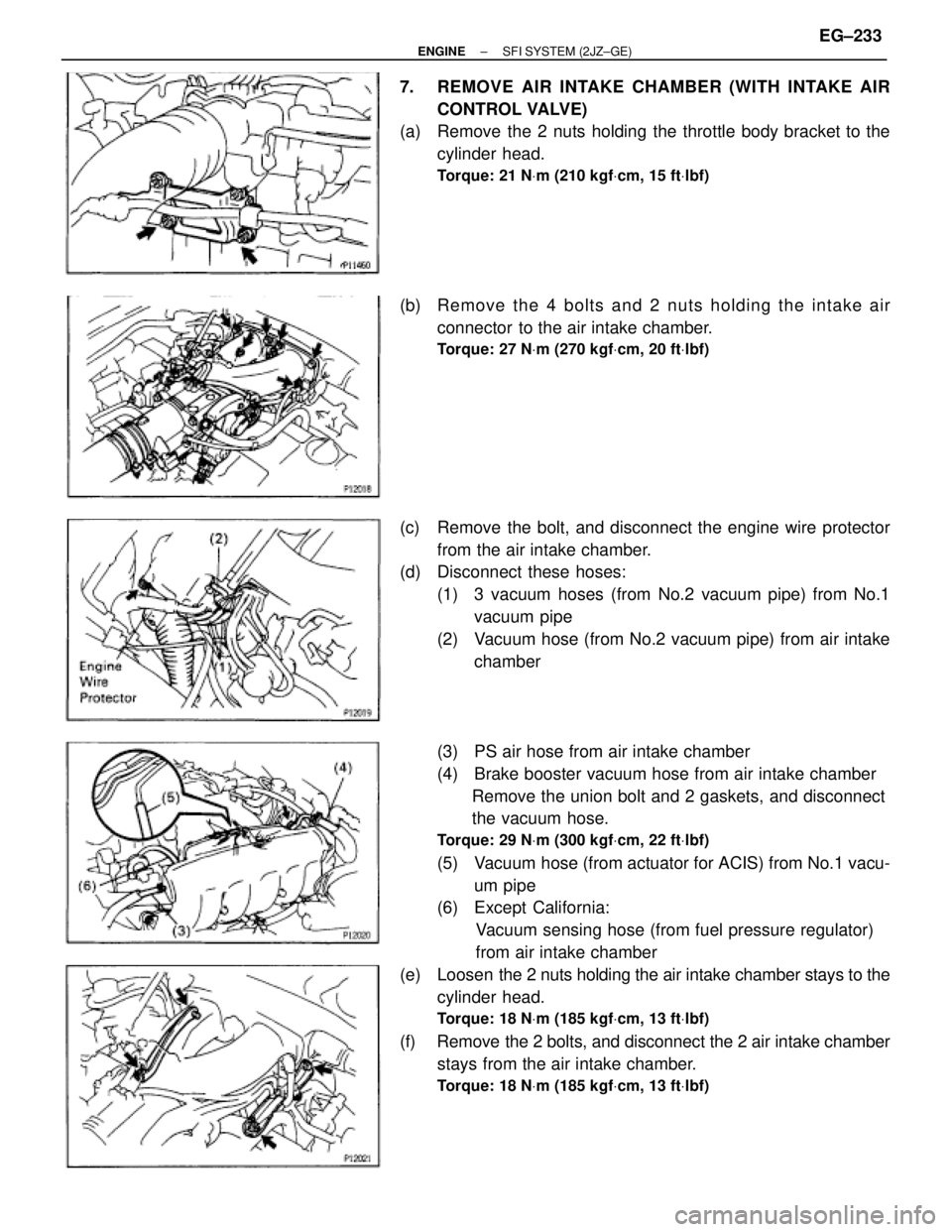
7. REMOVE AIR INTAKE CHAMBER (WITH INTAKE AIR
CONTROL VALVE)
(a) Remove the 2 nuts holding the throttle body bracket to the
cylinder head.
Torque: 21 NVm (210 kgfVcm, 15 ftVlbf)
(b) Re mo ve th e 4 bo lts an d 2 nu ts ho ld in g th e in ta ke air
connector to the air intake chamber.
Torque: 27 NVm (270 kgfVcm, 20 ftVlbf)
(c) Remove the bolt, and disconnect the engine wire protector
from the air intake chamber.
(d) Disconnect these hoses:
(1) 3 vacuum hoses (from No.2 vacuum pipe) from No.1
vacuum pipe
(2) Vacuum hose (from No.2 vacuum pipe) from air intake
chamber
(3) PS air hose from air intake chamber
(4) Brake booster vacuum hose from air intake chamber
Remove the union bolt and 2 gaskets, and disconnect
the vacuum hose.
Torque: 29 NVm (300 kgfVcm, 22 ftVlbf)
(5) Vacuum hose (from actuator for ACIS) from No.1 vacu-
um pipe
(6) Except California:
Vacuum sensing hose (from fuel pressure regulator)
from air intake chamber
(e) Loosen the 2 nuts holding the air intake chamber stays to the
cylinder head.
Torque: 18 NVm (185 kgfVcm, 13 ftVlbf)
(f) Remove the 2 bolts, and disconnect the 2 air intake chamber
stays from the air intake chamber.
Torque: 18 NVm (185 kgfVcm, 13 ftVlbf)
± ENGINESFI SYSTEM (2JZ±GE)EG±233
Page 1527 of 2543
C. Inspect VSV operation
(a) Check that air flows from port E to the filter.
(b) Apply battery voltage across the terminals.
(c) Check that air flows from port E to F.
If operation is not as specified, replace the VSV.
3. REINSTALL VSV
VSV FOR FUEL PRESSURE CONTROL
(California only)
COMPONENTS FOR REMOVAL AND
INSTALLATION
± ENGINESFI SYSTEM (2JZ±GE)EG±237
Page 1542 of 2543
FUEL PUMP ECU
COMPONENTS FOR REMOVAL AND
INSTALLATION
FUEL PUMP ECU INSPECTION
1. REMOVE FUEL PUMP ECU
2. INSPECT FUEL PUMP ECU
(See circuit inspection in Engine Troubleshooting)
3. REINSTALL FUEL PUMP ECU EG±252
± ENGINESFI SYSTEM (2JZ±GE)